USDT 3000 Temperature Differential Controller with two Relays
USDT 3000 Temperature Differential Controller with two Relays
USDT 3000 Temperature Differential Controller with two Relays

You also want an ePaper? Increase the reach of your titles
YUMPU automatically turns print PDFs into web optimized ePapers that Google loves.
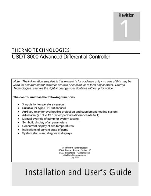
Revision<br />
1<br />
THERMO TECHNOLOGIES<br />
<strong>USDT</strong> <strong>3000</strong> Advanced <strong>Differential</strong> <strong>Controller</strong><br />
Note: The information supplied in this manual is for guidance only - no part of this may be<br />
used for any agreement, whether express or implied, or to form any contract. Thermo<br />
Technologies reserves the right to change specifications <strong>with</strong>out prior notice.<br />
The control unit has the following functions:<br />
• 3 inputs for temperature sensors<br />
• Suitable for type PT1000 sensors<br />
• Auxiliary relay for overheating protection and supplement heating system<br />
• Adjustable (2 o C to 19 o C) temperature difference (delta T)<br />
• Manual override of pump for system testing<br />
• Symbolic display of all parameters<br />
• Concurrent display of <strong>two</strong> temperatures<br />
• Indications of current state of pump<br />
• System status and diagnostic displays<br />
© Thermo Technologies<br />
5560 Sterrett Place • Suite 115<br />
Phone 410.997.0778 • Fax 410.997.0779<br />
e-Mail info@thermotechs.com<br />
July, 2004<br />
Installation and User’s Guide
Introduction<br />
T<br />
he <strong>USDT</strong> <strong>3000</strong> unit is a multifunctional temperature differential controller. It can be used<br />
in a wide range of applications. At the factory, it is set to control a standard solar water<br />
heating system <strong>with</strong> an auxiliary relay to divert surplus heat. The auxiliary relay can be used to<br />
maintain the tank temperature. It can protect the system from overheating or using another heat<br />
source to heat the storage tank. The controller has inputs for three PT1000-sensors. A 3-keypanel<br />
below a large LCD serves as the user interface. Simple icons give information about the<br />
function and operational mode of the controller and the system performance.<br />
Principle of Operation – In the simplest form the solar system needs <strong>two</strong> sensors. One is<br />
positioned at the collector, S1, to monitor the collector temperature (T C ). The second is positioned<br />
at the location S2 such that it measures the temperature of<br />
the heat transfer fluid inflowing into the collector. (T S ,<br />
bottom of the storage tank after the storage tank extracts<br />
the heat from the collector.) As the sun shines on the<br />
collector, the collector sensor picks up the temperature rise<br />
while the return sensor (T S ) remains at the existing<br />
temperature. The difference between these <strong>two</strong><br />
temperatures is referred to as delta T. The solar pump A1<br />
runs while delta T exceeds the adjustable temperature<br />
difference. To avoid overheating, the Auxiliary relay (R2)<br />
can be used to divert the surplus energy if the tank sensor<br />
S3 reaches its set point.<br />
The pump A1 runs only when the temperature at the<br />
collector sensor location S1 is higher than the return temperature at location S2 by at least delta<br />
T. The pump stops if delta T is less than the preset value:<br />
A1 (ON) only for S1 > (S2 + Delta T)<br />
S1<br />
A1<br />
S2<br />
S3<br />
The third sensor can be used for temperature monitoring of the tank and activation of R2 relay as<br />
the above example shows. Its function is totally independent from controller operation condition.<br />
1
INSTALLATION<br />
Note: This installation procedure is for guidance only, and the installer should verify its<br />
suitability. Make sure that the solar/boiler system is physically installed, manually tested, and is<br />
ready for controlled operation.<br />
T he following safety precautions are strongly recommended:<br />
1. Before attempting to install and operate the unit read this instruction manual carefully.<br />
2. Only suitably qualified personnel should carry out installation and any maintenance required.<br />
3. It is recommended that the unit be connected to the power supply via a suitably 6 amps<br />
isolating switch.<br />
4. The unit is designed for indoor use only. It is not suitable for installation in hazardous<br />
locations and should be protected from electromagnetic field.<br />
5. WARNING: When the unit is connected to the 115-volt power supply and the cover is<br />
opened, high voltage circuits will be exposed. Therefore, when installing the unit ensure<br />
all required connections are made and the cover is attached to the controller box before<br />
turning the power on. Ensure that all the connections are secure. If any maintenance work is<br />
required ensure that the unit is isolated from the power supply before removing the cover.<br />
Never leave the unit unattended if the cover has been removed and the power supply<br />
is connected.<br />
6. Do not exceed unit ratings of 2.15 amps (1/6 HP or 245 Watts pump).<br />
7. It is advisable to route power cables away from sensor cables.<br />
S<br />
ensor installation: <strong>Temperature</strong> sensors may be installed in fluid lines by inserting it<br />
into a sensor pocket or strapping it directly to the pipe. For the system to function<br />
correctly, it is very important that the sensors are located and installed properly. The collector<br />
sensor should be installed at the upper part (collector outlet) of the collector. If you are using a<br />
sensor pocket, make absolutely sure that the sensors are pushed completely into the sensor<br />
pockets. (Sensor pockets are not supplied.) Sensors must be well insulated in order to prevent<br />
them from being influenced by the surrounding temperature.<br />
When sensors are used outdoors, no water should be allowed to get into the immersion sleeves<br />
(lasting impedance change). Generally, sensors should not be exposed to moisture (e.g.<br />
2
condensation) as this can diffuse through the cast resin and damage the sensor. If exposed to<br />
moisture, heating at approx. 195 °F for one hour may possibly save the sensor.<br />
When sensors are used in open loops or swimming pools, make absolutely sure that immersion<br />
sleeves (sensor pockets) are corrosion-resistant.<br />
• Collector sensor FKP6 (Black Cable, Five Feet): The cable of the collector sensor is<br />
silicone coated and is temperature and weather resistant. Insert the sensor sleeve into a thermowell<br />
(sensor pocket), or strap it to the collector outlet pipe that projects from the collector housing.<br />
The best practice to house the collector sensor is to install a suitable sensor pocket into a T-piece<br />
on the collector outlet pipe. It is good practice to shield the sensor cable and its extension from<br />
UV rays and moisture.<br />
• Hot water return sensor FRP6 (Gray Cable, Nine Feet): The return (collector inlet) sensor<br />
should be installed <strong>with</strong> an immersion thermo-well in the return leg (cold side) of the heat<br />
exchanger. If there is no provision for a tank sensor, it is advisable to push the sensor sleeve<br />
beneath the insulation – keeping it close to the inner tank wall at the desired tank location. The<br />
sensor required for the solar loop “cold” leg is installed usually in the lowest part of the storage<br />
tank.<br />
• Clip-on installation: The Sensor is best secured to the appropriate line <strong>with</strong> pipe clamps,<br />
clips, etc. whereby you must make sure that the material is suitable (non-corrosive, heat-proof,<br />
etc.). It is advisable to insulate the sensor in order to measure the pipe temperature accurately<br />
and to prevent any influence from surrounding temperature.<br />
• Pool sensor installation: Place a heat conductive T-piece on the suction line directly at the<br />
pool outlet and screw in the sensor <strong>with</strong> an immersion sleeve (check corrosion resistance of the<br />
material used). Another possibility would be to attach the sensor at the same place <strong>with</strong> clips or<br />
adhesive tape, using appropriate thermal insulation against environmental influences.<br />
• Sensor cable extension: Sensor cables (22/4 AWG telephone cable) can be extended up<br />
to 150 ft.<br />
C ontroller unit installation: For viewing comfort, the controller unit should be<br />
positioned at eye level. It is always good practice to keep<br />
electronic equipment away from cold and heat, as extremes<br />
of temperature may reduce the lifetime of these devices. It is<br />
also good practice to keep electronic equipment away from<br />
heavy electrical loads, switches or contactors as these may<br />
cause electrical and electromagnetic interference when<br />
switched on or off.<br />
1. Unscrew the cross-recessed screw off the cover and<br />
remove it from the housing.<br />
2. Mark the upper fastening point on the wall and install<br />
the enclosed dowel and screw it in.<br />
3. Hang up the housing at the upper fastening point and<br />
secure the base unit using the lower fastening hole.<br />
3
Wire Connection: A small blade screwdriver may be used to fasten miniaturized terminal block<br />
screws while the corresponding wire is inserted.<br />
Caution: <strong>Controller</strong> wiring should only be done when the unit is not energized. It is possible to<br />
damage the control unit if it is assembled under voltage. Miniaturized terminal blocks are used for<br />
making wiring connections. The wire is held in place <strong>with</strong>in the terminal <strong>with</strong> a screw that provides<br />
excellent contact <strong>with</strong>out damage to the wire.<br />
Use up to an 18 AWG stranded wire to connect the sensor cables to the unit.<br />
• S1 collector sensor (higher temperature) 1 & 2<br />
• S2 return sensor (lower temperature) 3 & 4<br />
• S3 tank sensor (additional measure point) 5 & 6<br />
• Ground terminals 12, 13, 14<br />
• Relay R2, auxiliary relay for heat extraction<br />
R2 live line (Black) 16<br />
N neutral conductor (White) 15<br />
Ground clamp (Green) 14<br />
• Relay R1, solar loop pump<br />
R1 live line (Black) 18<br />
N neutral conductor (White) 17<br />
Ground clamp (Green) 13<br />
• Power Supply, 120 V AC<br />
L live line (Black) 20<br />
N neutral conductor (White) 19<br />
Ground clamp (Green) 12<br />
4
P<br />
ower Connections: A small blade screwdriver may be used to fasten miniaturized<br />
terminal block screws while the corresponding wire is inserted.<br />
NOTE 1: Always disconnect the controller from power supply before opening the housing.<br />
NOTE 2: The controller should be properly grounded. Flexible wires, 18/3 AWG<br />
(gauge/conductor), simplify connection to the terminals. The power terminal block will<br />
accommodate wire sizes to 14 AWG. All other connections should be secured and adequately<br />
tightened, as loose power connections will over-heat, and may cause fire.<br />
NOTE 3: It is important that the specified output loads (245 Watts) are not exceeded. Where<br />
these loads expect to exceed, external relays must be used. Always keep power cables away<br />
from sensor cables and other low voltage signal cables.<br />
NOTE 4: To protect against lightning damage, the system must be grounded according to local<br />
regulations. Sensor failures due to the weather or electrostatic are mostly due to poor grounding.<br />
5
OPERATION<br />
Adjustment keys: The <strong>USDT</strong> <strong>3000</strong> user interface is accessible via the three<br />
pushbuttons. The forward key (1) is used for scrolling forward through the indication<br />
menu or to increase the adjustment values. The backwards key (2) is accordingly used for the<br />
reverse function.<br />
To enter the parameter adjustment mode hold the forward key for 2 sec while HO is displayed.<br />
The “SEt” icon will be displayed on upper corner of LCD once<br />
you are in the adjustment mode. Now, you can select the<br />
parameter you wish to adjust by using the forward and<br />
backwards keys. Press the key “SEt” (3) in order to change the<br />
selected parameter:<br />
• Select a parameter by keys 1 and 2<br />
• Shortly press key 3, so that “SEt” flashes<br />
• Adjust the value by keys 1 and 2<br />
• Press key 3, so that “SEt” permanently appears, the adjusted value is now saved<br />
Please note: The circulation pump (A1) stops at tank temperature of 90 °C to avoid tank<br />
overheating.<br />
Parameter List<br />
TC<br />
TS<br />
TT<br />
HO<br />
DO<br />
DF<br />
SX<br />
CL<br />
CX<br />
CN<br />
TO<br />
TF<br />
FN<br />
MM<br />
PG<br />
VN<br />
Collector temperature<br />
Tank (return) temperature<br />
Thermostat temperature (control temperature for R2 relay)<br />
Solar operating hours (to be used for energy calculation)<br />
Pump starting temperature difference<br />
Pump switch off temperature difference<br />
Maximum tank temperature<br />
Collector limiting temperature<br />
Maximum collector temperature<br />
Minimum collector temperature<br />
Thermostat (R2) switch on temperature<br />
Thermostat (R2) switch off temperature<br />
Function:<br />
0 : Maximum tank temperature disable<br />
1 : Maximum tank temperature enable<br />
2 : Maximum tank temperature disable, cooling function enable<br />
3 : Maximum tank temperature enable, cooling function enable<br />
Manual operation mode:<br />
0 : relays R1 and R2 are deactivated<br />
1 : relay R1 is activated, relay R2 is deactivated<br />
2 : relay R1 is deactivated, relay R2 is activated<br />
3 : relays R1 and R2 are activated<br />
4 : automatic operation<br />
Program number<br />
Version number<br />
6
Examples<br />
Delta T Adjustment -The controller monitors temperatures at<br />
S1 and S2 locations and compares the resulting temperature<br />
difference <strong>with</strong> delta T. The solar loop circulation pump (A1)<br />
runs, when the measured temperature difference delta T is<br />
higher than or identical to the set value (DO). The pump stops<br />
at the shut off temperature (DF). The Following parameters are<br />
factory defaults:<br />
DO 6 °C and DF 4 °C<br />
Maximum Tank <strong>Temperature</strong> (SX) - The solar pump A1 stops<br />
(R1) to avoid tank overheating (safety shutdown of the tank) at<br />
this (SX) set point. The overheating symbol flashes if the<br />
maximum tank temperature is exceeded. The factory setting is<br />
(see FN =3) 60 °C. To disable this protective feature of the<br />
unit, change FN to 0.<br />
Solar Loop Limiting <strong>Temperature</strong> - If the temperature of the<br />
solar loop exceeds the set point temperat ure (CL), the solar<br />
pump A1 stops (R1) in order to protect the solar components<br />
from overheating (collector safety shutdown). The factory limit<br />
temperature is set to 140 °C but it can be changed <strong>with</strong>in the<br />
adjustment range of 110-200 °C. The operating control lamp<br />
flashes red if the temperature limit is exceeded.<br />
Maximum Collector <strong>Temperature</strong> (CX) – The pump A1 stops<br />
when the tank temperature reaches its set point (SX). The<br />
system will stagnate. When the collector exceeds its maximum<br />
design temperature (CX), the operating control lamp flashes<br />
green and the solar pump A1 (R1) comes on to “cool” the<br />
system. The tank temperature might increase above (SX), but<br />
only up to 90 °C (safety shutdown of the tank). This function<br />
guarantees a longer operating time for very hot summer days<br />
and ensures a thermal relief for the collectors and the system.<br />
The factory setting is 120 °C (shown in display), but it can be<br />
changed <strong>with</strong>in the adjustment range of 100 -190 °C.<br />
Minimum Collector <strong>Temperature</strong> (CN) - The minimum<br />
collector temperature is a minimum switching temperature. It<br />
must be exceeded to turn the solar pump A1 (R1) on. The<br />
minimum temperature reduces pump cycling at low solar<br />
radiation times such as early morning.<br />
7
The factory setting is 10 °C that disables this feature. User can<br />
change this set point from –10 to + 90:<br />
• Use –10.0 to 9.9 for frost protection in sunbelt regions<br />
• Use 10.1 to 90 to permit start-up operation<br />
Heat Extraction (FN 2) – While the tank temperature is higher<br />
than (SX), the solar pump runs until the tank temperature drops<br />
below the maximum tank temperature (SX). This feature avoids<br />
overheating and pre-mature temperature safety valve operation.<br />
It can happen only if hot water consumption is below the system<br />
capacity such as holidays or low hot water usage.<br />
Collector Cooling Function (FN 3) - When the maximum tank<br />
temperature (SX) is reached, the solar pump A1 (R1) stops. The<br />
collector temperature now rises to the maximum collector<br />
temperature (CX). At this temperature the solar pump starts<br />
again to extract heat from the collector. The tank temperature<br />
may increase (SX) - but only up to 90 °C (system overheating<br />
safety shutdown). The solar pump stops if the tank temperature<br />
approaches 90 °C. It runs again to reduce the tank temperature<br />
if the collector temperature is at least 5K below the tank<br />
temperature.<br />
Thermostat Function (TT) – The <strong>USDT</strong> <strong>3000</strong> is equipped <strong>with</strong><br />
a 2nd relay (R2) and a 3rd temperature sensor input (S3, e.g.<br />
TT measures the upper tank temperature). It can be used for the<br />
tank temperature monitoring and safeguarding. It works<br />
independently from the solar operation. The relay (R2)<br />
operations are programmed by switch-on temperature (TO) and<br />
switch-off temperature (TF). They must be programmed in the<br />
corresponding windows. For example, it can be used to divert<br />
the collected energy to another user after reaching the desired<br />
tank temperature. TO and TF are disabled by setting them to 40<br />
°C at the factory:<br />
• TO = TF (R2) relay is energized only if the maximum<br />
tank temperature is reached<br />
• TO > TF to be used to divert the surplus heat<br />
• TO < TF to be used <strong>with</strong> an auxiliary heating system<br />
8
T<br />
ROUBLESHOOTING<br />
Problem: Nothing happens when unit is powered-up.<br />
Cause/Remedy: The fuse could be blown – check and replace if necessary. If the fuse blows<br />
again, then the pump draws more current than the unit is design to supply. Use an auxiliary relay<br />
or contact your product supplier.<br />
Problem: Operating control red lamp is flashing.<br />
Cause/Remedy: This indicates a system alarm warning, which may be caused by a sensor fault:<br />
• Error code –888.8 is displayed è (TC, TS or TT) sensor cable is short circuited<br />
• Error code 888.8 is displayed è (TC, TS or TT) sensor cable is open<br />
Following table shows the impedance characteristics of PT 1000 sensors:<br />
o<br />
C - 10 0 10 20 30 40 50 60 70 80 90 100 110<br />
o F 14 32 50 68 86 104 122 140 158 176 194 212 230<br />
OHM 961 1000 1039 1078 1117 1155 1194 1232 1271 1309 1347 1385 1423<br />
S<br />
PECIFICATION<br />
Supply Voltage<br />
Fuse<br />
Phantom Load<br />
Hysteresis<br />
Delta T<br />
Overheating Range<br />
120 V AC<br />
4 A<br />
max. 2 W<br />
6 degrees<br />
4 – 24 o F<br />
100 – 200 o F<br />
9