USDT 3004 *49012820* 49012820 - Thermomax Technologies
USDT 3004 *49012820* 49012820 - Thermomax Technologies
USDT 3004 *49012820* 49012820 - Thermomax Technologies

Create successful ePaper yourself
Turn your PDF publications into a flip-book with our unique Google optimized e-Paper software.
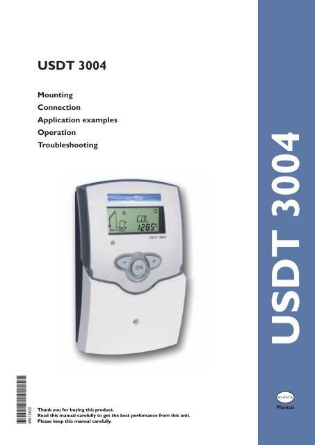
<strong>USDT</strong> <strong>3004</strong><br />
Mounting<br />
Connection<br />
Application examples<br />
Operation<br />
Troubleshooting<br />
<strong>USDT</strong> <strong>3004</strong><br />
<strong>*<strong>49012820</strong>*</strong><br />
<strong>49012820</strong><br />
Thank you for buying this product.<br />
Read this manual carefully to get the best perfomance from this unit.<br />
Please keep this manual carefully.<br />
en-US/CA<br />
Manual
<strong>USDT</strong> <strong>3004</strong><br />
Contents<br />
General...................................................................... 2<br />
Overview................................................................... 3<br />
1. Installation........................................................... 4<br />
1.1 Mounting.................................................................................4<br />
1.2 Electrical connection...........................................................4<br />
1.3 Data communication/ Bus..................................................5<br />
1.4 Terminal allocation in the different system layouts.....6<br />
System layout 1.....................................................................6<br />
System layout 2.....................................................................8<br />
System-specific functions................................................ 10<br />
System layout 3...................................................................12<br />
2. Operation and function.................................... 14<br />
2.1 Push buttons........................................................................14<br />
2.2 System monitoring display ...............................................14<br />
2.3 Flashing codes......................................................................15<br />
3. Commissioning.................................................. 16<br />
4. Channel overview............................................. 18<br />
4.1 Display channels..................................................................18<br />
4.2 Adjustment channels........................................................ 20<br />
5. Troubleshooting................................................ 27<br />
5.1 Various................................................................................. 28<br />
6. Accessories........................................................ 30<br />
Impressum.............................................................. 32<br />
General<br />
Safety advice:<br />
Please read the following information carefully before<br />
installing and operating the controller. In this way damage<br />
to the solar system caused by wrong installation will be<br />
avoided. Please make sure that the mounting is adapted to<br />
the characteristics of the building, that the local regulations<br />
are respected and is conform with the technical rules.<br />
Please pay attention to the following safety advice in order<br />
to avoid danger and damage to people and property.<br />
Subject to technical change. Errors excepted.<br />
Instructions:<br />
Attention should be paid to<br />
••<br />
Valid national and local standards and regulations<br />
••<br />
Respective valid standards and directives<br />
Equipment to be installed and used in accordance with<br />
the rules of the National Electrical Code (NEC) or with<br />
Canadian Electrical Code (CEC), Part I.<br />
These instructions are exclusively addressed to authorized<br />
skilled personnel.<br />
••<br />
Only qualified electricians should carry out installation<br />
and maintenance work.<br />
••<br />
Initial installation should be carried out by qualified personnel<br />
Description of symbols<br />
Information about the product<br />
WARNING!<br />
Warnings are indicated with a<br />
warning triangle!<br />
They contain information on how<br />
to avoid the danger described.<br />
Proper usage<br />
The solar controller is designed for use in solar thermal<br />
and heating systems in compliance with the technical data<br />
specified in these instructions.<br />
Improper use excludes all liability claims.<br />
Signal words describe the danger that may occur, when it<br />
is not avoided.<br />
Warning means that injury, possibly life-threatening injury,<br />
can occur.<br />
Attention means that damage to the appliance can occur.<br />
Note<br />
Notes are indicated with an information<br />
symbol.<br />
ÎÎArrows indicate instruction steps that should be<br />
carried out.<br />
Note<br />
Strong electromagnetic fields can impair the<br />
function of the controller.<br />
ÎÎMake sure the controller as well as the<br />
system are not exposed to strong electromagnetic<br />
fields.<br />
© 10259_usdt_<strong>3004</strong>.monus.indd<br />
| 2
6.1"<br />
155 mm<br />
<strong>USDT</strong> <strong>3004</strong><br />
Overview<br />
• System-monitoring-display<br />
• Up to 4 Pt1000 temperature sensors<br />
• semiconductor relay for pump speed control<br />
• 3 basic system layouts to choose from<br />
• Energy metering<br />
• VBus ®<br />
• Function control<br />
• Thermostat function (time controlled)<br />
• Control of the system by ServiceCenter<br />
software possible<br />
• User-friendly operation<br />
• Housing with outstanding design<br />
• Extra-low power consumption<br />
Included with the <strong>USDT</strong> <strong>3004</strong> :<br />
2.6"<br />
66 mm<br />
1 × <strong>USDT</strong> <strong>3004</strong><br />
1.1"<br />
28 mm<br />
1 × accessory bag<br />
1 × spare fuse T4A<br />
2 × screws and wall plugs<br />
4 × strain relief and screws<br />
6.8"<br />
172 mm<br />
1 × manual<br />
Additionally enclosed in the full kit:<br />
1 × sensor FKP6<br />
2 × sensor FRP6<br />
4.3"<br />
110 mm<br />
0.4" / 11 mm<br />
0.5" / 13 mm<br />
1.9" / 47 mm<br />
Technical data<br />
© 10259_usdt_<strong>3004</strong>.monus.indd<br />
Housing: plastic, PC-ABS and PMMA<br />
Protection type: IP 20 / EN 60529<br />
Ambient temp.: 32 ... 104 °F<br />
[0 ... 40 °C]<br />
Size: 6.8" × 4.3" × 1.9"<br />
172 × 110 × 47 mm<br />
Mounting: wall mounting, mounting<br />
into patch-panels is possible<br />
Display: System screen for system<br />
visualization, 16-segment display, 7-segment<br />
display, 8 symbols for system<br />
status and operating control lamp<br />
Operation: by 3 push buttons at the<br />
front of the housing<br />
Functions: Differential temperature<br />
controller with optional add-on system<br />
functions. Func ti on con trol, operating<br />
hours counter for solar pump, evacuated<br />
tube collector function, pump<br />
speed control, thermostat function,<br />
drainback and booster option, and<br />
energy metering.<br />
Inputs:<br />
for 4 Pt1000 temperature sensors<br />
Outputs: 2 semiconductor relays<br />
Bus: VBus ®<br />
Power supply: 100 ... 240 V~<br />
Standby power consumption:<br />
< 1 W<br />
Switching capacities:<br />
R1: 1 (1) A 100 ... 240 V~<br />
(semiconductor relay)<br />
R2: 1 (1) A 100 ... 240 V~<br />
(semiconductor relay)<br />
3 |
<strong>USDT</strong> <strong>3004</strong><br />
1. Installation<br />
1.1 Mounting<br />
display<br />
WARNING!<br />
Electric shock!<br />
Opening the housing will expose<br />
live parts!<br />
ÎÎ<br />
Switch off power supply and disconnect<br />
the device from power supply<br />
before opening the housing!<br />
cover<br />
The unit must only be installed<br />
push button<br />
••<br />
in a dry interior location<br />
••<br />
in a non-hazardous location<br />
••<br />
away from electromagnetic fields<br />
cable conduits with strain<br />
relief<br />
130 mm<br />
5.1“<br />
lower fastening<br />
upper fastening<br />
fuse 4A<br />
104 mm<br />
4.1“<br />
The controller must additionally be supplied from a doublepole<br />
switch with contact gap of at least 0.12" [3 mm].<br />
Route sensor cables and power supply cables separately.<br />
ÎÎUnscrew the cross-head screw from the cover and<br />
remove it along with the cover from the housing<br />
ÎÎMark the upper fastening point on the wall and drill<br />
ÎÎFasten the enclosed wall plug and screw leaving the<br />
head protruding<br />
ÎÎHang the housing from the upper fastening point and<br />
mark the lower fastening point through the hole in the<br />
terminal box (centers 5.1" [130 mm])<br />
ÎÎDrill and insert the lower wall plug<br />
ÎÎFasten the housing to the wall with lower fastening<br />
screw and tighten<br />
Î ÎComplete wiring connections in accordance with terminal<br />
allocations, see chap. 1.2 “Electrical connection”<br />
ÎÎPlace the cover back onto the housing<br />
ÎÎFasten the cover by means of the cross-head screw<br />
1.2 Electrical connection<br />
fuse<br />
ATTENTION!<br />
ESD damage!<br />
Electrostatic discharge can lead to damage<br />
to electronic components!<br />
ÎÎTake care to discharge properly<br />
before touching the inside of the<br />
device. To do so, touch a grounded<br />
surface such as a radiator or tap!<br />
sensor terminal<br />
VBus ®<br />
ground terminal<br />
load terminals<br />
power supply terminals<br />
Note:<br />
The minimum pump speed must be set to 100 %<br />
when auxiliary relays or valves are connected.<br />
© 10259_usdt_<strong>3004</strong>.monus.indd<br />
| 4
<strong>USDT</strong> <strong>3004</strong><br />
© 10259_usdt_<strong>3004</strong>.monus.indd<br />
12<br />
13<br />
14<br />
1.3 Data communication/ Bus The controller is equipped with a VBus ® for data transfer<br />
with and energy supply to external modules. The connection<br />
is carried out at the terminals marked “VBus” (either<br />
polarity). One or more VBus ® modules can be connected<br />
via this data bus, such as<br />
••<br />
GA3 large display, SD3 smart display<br />
••<br />
DL2 datalogger<br />
••<br />
VBus ® /USB or VBus ® /LAN interface adapter<br />
••<br />
VBus ® /PWM interface adapter<br />
••<br />
AM1 alarm module<br />
VBus ®<br />
connection terminals<br />
R1 1 (1) A ( 100 ... 240) V~<br />
R2 1 (1) A (100 ... 240) V~<br />
N R2<br />
15 16<br />
N<br />
17<br />
R1 N<br />
18 19<br />
Grounding and load terminals<br />
Temp. Sensor<br />
Pt1000<br />
S1 S2 S3<br />
1 2 3 4 5 6<br />
S4<br />
7 8<br />
Sensor terminals S1 ... S4<br />
L<br />
20<br />
Connecting the device to the power supply must always be<br />
the last step of the installation!<br />
The power supply to the controller must be carried out via<br />
an external power switch (last step!). The supply voltage<br />
must be 100 ... 240 V~ (50 ... 60 Hz). Flexible cables must<br />
be attached to the housing with the enclosed strain relief<br />
and the corresponding screws.<br />
The controller is equipped with 2 semiconductor relays,<br />
to which loads such as pumps, valves etc. can be connected:<br />
••<br />
Relay 1<br />
18 = conductor R1<br />
17 = neutral conductor N<br />
13 = ground conductor<br />
••<br />
Relay 2<br />
16 = conductor R2<br />
15 = neutral conductor N<br />
14 = ground conductor<br />
The power supply is to be carried out at the terminals:<br />
19 = neutral conductor N<br />
20 = conductor L<br />
12 = ground terminal<br />
The temperature sensors (S1 up to S4) are to be<br />
connected to the following terminals with either polarity:<br />
1 / 2 = Sensor 1 (e.g. Sensor collector)<br />
3 / 4 = Sensor 2 (e.g. Sensor tank)<br />
5 / 6 = Sensor 3 (e.g. Sensor tank top)<br />
7 / 8 = Sensor 4 (e.g. Sensor return)<br />
All Pt1000 temperature sensors are equipped with a<br />
platinum measuring element in their tip. The electrical<br />
resistance of the measuring element changes in relation<br />
to the temperature (see table in chap. 5).<br />
The difference between FKP and FRP type sensors only<br />
lies in the cable insulation material. The insulation material<br />
of FKP type sensor cables resists a higher temperature, so<br />
that FKP type sensors should be used as collector sensors.<br />
FRP type sensors are best used as reference sensors in<br />
tanks or pipes.<br />
••<br />
WMZ calorimeter module<br />
By means of a DL2 datalogger or an interface adapter,<br />
the controller can be connected to a PC or a computer<br />
network. With the ServiceCenter Software (RSC) the<br />
controller measurements can be read out, processed and<br />
visualized. The software allows easy function control of the<br />
system. For the remote parametrisation of the controller, a<br />
special software tool will be available for download, soon.<br />
5 |
<strong>USDT</strong> <strong>3004</strong><br />
1.4 Terminal allocation in the different system layouts<br />
System layout 1<br />
The controller calculates the temperature difference between<br />
collector sensor S1 and tank sensor S2. If the difference<br />
is larger than or identical to the adjusted switch-on<br />
temperature difference (DT O), the solar pump will be<br />
operated by relay 1, and the tank will be loaded until the<br />
switch-off temperature difference (DT F) or the maximum<br />
tank temperature (S MX) is reached.<br />
Sensors S3 and S4 can optionally be connected for measurement<br />
purposes.<br />
If energy metering (OHQM) is activated, sensor S4 has to<br />
be connected as return sensor.<br />
If the drainback option (ODB) is activated, relay 2 can be<br />
used to operate a booster pump by activating the booster<br />
function (OBST).<br />
Arr 1<br />
S1<br />
R1<br />
S3<br />
S1 exemplary<br />
Drainback system layout<br />
(with booster pump)<br />
R1<br />
R2<br />
S4 / TR<br />
S2<br />
S4/TR<br />
S3<br />
S2<br />
Display Channels<br />
Channel Description Terminal Page<br />
INIT x* ODB initialization active - 18<br />
FLL x* ODB filling time active - 18<br />
STAB x* ODB stabilization in progress - 18<br />
COL x Temperature collector S1 18<br />
TST x Temperature tank S2 18<br />
S3 x Temperature sensor 3 S3 18<br />
S4 x Temperature sensor 4 S4 18<br />
TR x* Temperature return sensor S4 18<br />
n % x Pump speed R1 R1 19<br />
hP x Operating hours R1 R1 19<br />
hP1 x* Operating hours R1 (if OBST is activated) R1 19<br />
hP2 x* Operating hours R2 (if OBST is activated) R2 19<br />
kWh x* Heat quantity kWh - 19<br />
MWh x* Heat quantity MWh - 19<br />
TIME x Time - 16<br />
© 10259_usdt_<strong>3004</strong>.monus.indd<br />
| 6
<strong>USDT</strong> <strong>3004</strong><br />
Adjustment Channels<br />
Channel Description Factory setting Page<br />
Arr x System 1 20<br />
DT O x Switch-on temperature difference 12.0 °Ra [6.0 K] 20<br />
DT F x Switch-off temperature difference 8.0 °Ra [4.0 K] 20<br />
DT S x Nominal temperature difference 20.0 °Ra [10.0 K] 20<br />
RIS x Rise control R1 4 °Ra [2 K] 20<br />
nMN x Minimum pump speed 30 % 20<br />
S MX x Maximum tank temperature 140 °F [60 °C] 21<br />
EM<br />
Legend:<br />
x<br />
Emergency temperature collector 270 °F [130 °C] 21<br />
Emergency temperature collector if ODB is activated: 200 °F [95 °C] 21<br />
OCC x Option collector cooling OFF 22<br />
CMX x* Maximum collector temperature 230 °F [110 °C] 22<br />
OSYC x Option system cooling OFF 22<br />
DTCO x* Cooling switch-on temperature difference 40.0 °Ra [20.0 K] 22<br />
DTCF x* Cooling switch-off temperature difference 30.0 °Ra [15.0 K] 22<br />
OSTC x Option tank cooling OFF 23<br />
OHOL x* Option holiday cooling OFF 23<br />
THOL x* Holiday cooling temperature 110 °F [40 °C] 23<br />
OCN x Option minimum limitation OFF 23<br />
CMN x* Minimum collector temperature 50 °F [10 °C] 23<br />
OCF x Option antifreeze OFF 23<br />
CFR x* Antifreeze temperature 40.0 °F [4.0 °C] 23<br />
O TC x Option tube collector OFF 24<br />
TCST x* OTC starting time 07:00 24<br />
TCEN x* OTC ending time 19:00 24<br />
TCRU x* OTC runtime 30 s 24<br />
TCIN x* OTC standstill interval 30 min 24<br />
OHQM x Option energy metering OFF 24<br />
FMAX x* Maximum flow 6.0 l 24<br />
MEDT x* Antifreeze type 1 24<br />
MED% x* Antifreeze concentration (only if MEDT = propylene or ethylene) 45 % 24<br />
ODB x Drainback option OFF 25<br />
tDTO x* ODB switch-on condition - time period 60 s 25<br />
tFLL x* ODB filling time 5.0 min 25<br />
tSTB x* ODB stabilization time 2.0 min 25<br />
OBST s* Option booster function OFF 25<br />
MAN1 x Manual operation R1 Auto 26<br />
MAN2 x Manual operation R2 Auto 26<br />
LANG x Language En 26<br />
UNIT x Temperature unit °C 26<br />
RESE x Reset - back to factory defaults 26<br />
W0040100 Version number<br />
Symbol<br />
Specification<br />
x Channel is available<br />
x* Channel is available if the corresponding option is activated.<br />
s* System-specific channel, only available if the corresponding option is activated<br />
© 10259_usdt_<strong>3004</strong>.monus.indd<br />
7 |
<strong>USDT</strong> <strong>3004</strong><br />
System layout 2<br />
The controller calculates the temperature difference between<br />
collector sensor S1 and tank sensor S2. If the difference<br />
is larger than or identical to the adjusted switch-on<br />
temperature difference (DT O), the solar pump will be<br />
operated by relay 1, and the tank will be loaded until the<br />
switch-off temperature difference (DT F) or the maximum<br />
tank temperature (S MX) is reached.<br />
Sensor S3 is used for a thermostatic function, which ope-<br />
rates relay 2 for backup heating or heat dump purposes,<br />
when the adjusted thermostat switch-on temperature<br />
(AH O) is reached. This function can optionally be combined<br />
with up to three adjustable time frames.<br />
Sensor S3 can also be optionally used as a reference sensor<br />
for the thermal disinfection function OTD.<br />
Sensor S4 can optionally be connected for measurement<br />
purposes. If energy metering (OHQM) is activated, sensor<br />
S4 has to be connected as return sensor.<br />
Arr 2<br />
S1<br />
R1<br />
S3<br />
R2<br />
S4 / TR<br />
S2<br />
Display Channels<br />
Channel Description Terminal Page<br />
INIT x* ODB initialization active - 18<br />
FLL x* ODB filling time active - 18<br />
STAB x* ODB stabilization in progress - 18<br />
COL x Temperature collector S1 18<br />
TSTB x Temperature tank 1 bottom S2 18<br />
TSTT x Temperature tank 1 at the top S3 18<br />
TDIS s* Thermal disinfection temperature S3 18<br />
S4 x Temperature sensor 4 S4 18<br />
TR x* Temperature return sensor S4 18<br />
n1 % x Pump speed R1 R1 19<br />
h P1 x Operating hours R1 R1 19<br />
h P2 x Operating hours R2 R2 19<br />
kWh x* Heat quantity kWh - 19<br />
MWh x* Heat quantity MWh - 19<br />
CDIS s* Countdown of monitoring period - 19<br />
SDIS s* Starting time display - 19<br />
DDIS s* Heating period display - 19<br />
TIME x Time - 16<br />
| 8<br />
© 10259_usdt_<strong>3004</strong>.monus.indd
<strong>USDT</strong> <strong>3004</strong><br />
© 10259_usdt_<strong>3004</strong>.monus.indd<br />
Adjustment Channels<br />
Channel Description Factory setting Page<br />
Arr x System 2 20<br />
DT O x Switch-on temperature difference 12.0 °Ra [6.0 K] 20<br />
DT F x Switch-off temperature difference 8.0 °Ra [4.0 K] 20<br />
DT S x Nominal temperature difference 20.0 °Ra [10.0 K] 20<br />
RIS x Rise control R1 4 °Ra [2 K] 20<br />
n1MN x Minimum pump speed R1 30 % 20<br />
S MX x Maximum tank temperature 140 °F [60 °C] 21<br />
EM<br />
x<br />
Emergency temperature collector 270 °F [130 °C] 21<br />
Emergency temperature collector if ODB is activated: 200 °F [95 °C] 21<br />
OCC x Option collector cooling OFF 22<br />
CMX x* Maximum collector temperature 230 °F [110 °C] 22<br />
OSYC x Option system cooling OFF 22<br />
DTCO x* Cooling switch-on temperature difference 40.0 °Ra [20.0 K] 22<br />
DTCF x* Cooling switch-off temperature difference 30.0 °Ra [15.0 K] 22<br />
OSTC x Option tank cooling OFF 23<br />
OHOL x* Option holiday cooling OFF 23<br />
THOL x* Holiday cooling temperature 110 °F [40 °C] 23<br />
OCN x Option minimum limitation OFF 23<br />
CMN x* Minimum collector temperature 50 °F [10 °C] 23<br />
OCF x Option antifreeze OFF 23<br />
CFR x* Antifreeze temperature 40.0 °F [4.0 °C] 23<br />
O TC x Option tube collector OFF 24<br />
TCST x* OTC starting time 07:00 24<br />
TCEN x* OTC ending time 19:00 24<br />
TCRU x* OTC runtime 30 s 24<br />
TCIN x* OTC standstill interval 30 min 24<br />
OHQM x Option energy metering OFF 24<br />
FMAX x* Maximum flow 6.0 l 24<br />
MEDT x* Antifreeze type 1 24<br />
MED% x* Antifreeze concentration 45 % 24<br />
AH O s Switch-on temp. for thermostat 1 110 °F [40 °C] 10<br />
AH F s Switch-off temp. for thermostat 1 120 °F [45 °C] 10<br />
t1 O s Switch-on time 1 thermostat 00:00 10<br />
t1 F s Switch-off time 1 thermostat 00:00 10<br />
t2 O s Switch-on time 2 thermostat 00:00 10<br />
t2 F s Switch-off time 2 thermostat 00:00 10<br />
t3 O s Switch-on time 3 thermostat 00:00 10<br />
t3 F s Switch-off time 3 thermostat 00:00 10<br />
ODB x Drainback option OFF 25<br />
tDTO x* ODB switch-on condition - time period 60 s 25<br />
tFLL x* ODB filling time 5.0 min 25<br />
tSTB x* ODB stabilization time 2.0 min 25<br />
OTD s Option thermal disinfection OFF 11<br />
PDIS s* Monitoring period 01:00 11<br />
DDIS s* Heating period 01:00 11<br />
TDIS s* Disinfection temperature 140 °F [60 °C] 11<br />
SDIS s* Starting time 00:00 11<br />
MAN1 x Manual operation R1 Auto 26<br />
MAN2 x Manual operation R2 Auto 26<br />
LANG x Language En 26<br />
UNIT x Temperature unit °C 26<br />
RESE x Reset - back to factory defaults 26<br />
W0040100 Version number<br />
Legend:<br />
Symbol<br />
Specification<br />
x Channel is available<br />
x* Channel is available if the corresponding option is activated.<br />
s Channel is specifically available in this system layout<br />
s* System-specific channel, only available if the corresponding option is activated<br />
9 |
<strong>USDT</strong> <strong>3004</strong><br />
System-specific functions<br />
The following functions are exclusively available in system<br />
layout 2. The corresponding channels will not be available in<br />
any other system layout.<br />
Thermostat function<br />
Backup heating<br />
Use of surplus energy<br />
The thermostat function works independently from the<br />
solar operation and can be used for using surplus energy<br />
or for backup heating.<br />
• AH O < AH F<br />
thermostat function for backup heating<br />
• AH O > AH F<br />
thermostat function for using surplus energy<br />
The symbol will be shown on the display if the second<br />
relay output is activated.<br />
Reference sensor for the thermostat function is S3!<br />
AH O:<br />
Thermostat switch-on tem p.<br />
Adjustment range:<br />
30.0 ... 200.0 °F<br />
[0.0 ... 95.0 °C]<br />
in steps of 1.0 °Ra [0.5 K]<br />
Factory setting:<br />
110.0°F [40.0 °C]<br />
AH F:<br />
Thermostat switch-off tem p.<br />
Adjustment range:<br />
30.0 ... 200.0 °F<br />
[0.0 ... 95.0 °C]<br />
in steps of 1.0 °Ra [0.5 K]<br />
Factory setting:<br />
120.0 °F [45.0 °C]<br />
t1 O, t2 O, t3 O:<br />
Thermostat switch-on time<br />
Adjustment range:<br />
00:00 ... 23:45<br />
Factory setting: 00:00<br />
t1 F, t2 F, t3 F:<br />
Thermostat switch-off time<br />
Adjustment range:<br />
00:00 ... 23:45<br />
Factory setting: 00:00<br />
In order to block the thermostat function for a certain<br />
period, there are three time frames t1 ... t3. If the function<br />
should be active between 6:00 and 9:00, set t1 O to 6:00<br />
and t1 F to 9:00.<br />
If all time frames are set to 00:00 o’clock, the thermostat<br />
function is continuously activated (factory setting).<br />
© 10259_usdt_<strong>3004</strong>.monus.indd<br />
| 10
<strong>USDT</strong> <strong>3004</strong><br />
Option: Thermal disinfection of the upper DHW<br />
zone (OTD)<br />
OTD:<br />
Thermal disinfection function<br />
Adjustment range: ON / OFF<br />
Factory setting: OFF<br />
PDIS:<br />
Monitoring period<br />
Adjustment range:<br />
0 ... 30:0 ... 24 h (dd:hh)<br />
Factory setting: 01:00<br />
DDIS<br />
Heating period<br />
Adjustment range:<br />
00:00 ... 23:59 (hh:mm)<br />
Factory setting: 01:00<br />
TDIS<br />
Disinfection temperature<br />
Adjustment range:<br />
30 ... 200 °F<br />
[0 ... 95 °C]<br />
in steps of 2 °Ra [1 K]<br />
Factory setting:<br />
140 °F [60 °C]<br />
This function is used for protecting the upper tank zone<br />
against Legionella by activating the backup heating.<br />
Reference sensor for the thermal disinfection is S3!<br />
ÎÎTo activate the function, select “On” in the OTD<br />
channel.<br />
For thermal disinfection, the temperature in the upper<br />
DHW tank zone has to be monitored. This protection is<br />
ensured when, during the monitoring period (PDIS), the<br />
disinfection temperature (TDIS) is continuously exceeded<br />
for the entire heating period (DDIS). S3 is used as the<br />
reference sensor and displayed as TSTT.<br />
If OTD is activated, PDIS will start as soon as the temperature<br />
at S3 falls below TDIS. In the display channel<br />
CDIS, the remaining time of PDIS is counted backwards.<br />
If, during the monitoring period, the temperature at S3<br />
exceeds TDIS continuously for the duration of DDIS,<br />
thermal disinfection is considered complete and a new<br />
monitoring period begins.<br />
If CDIS counts down to 00:00, relay 2 will be operated in<br />
order to use the backup heating for thermal disinfection.<br />
CDIS will then be replaced with a display channel DDIS<br />
showing the adjusted heating period. DDIS will start counting<br />
down the heating period as soon as TDIS is exceeded<br />
at S3. As long as DDIS is active, the temperature at S3 will<br />
be displayed as TDIS instead of TSTT.<br />
If, during DDIS, the temperature at S3 exceeds TDIS by<br />
more than 10 °Ra [5 K], relay 2 is switched off until the<br />
temperature falls below TDIS + 4 °Ra [2 K].<br />
If, during DDIS, the temperature at S3 falls below TDIS,<br />
the heating period will restart. DDIS can only be completed<br />
when TDIS is exceeded without interruption.<br />
© 10259_usdt_<strong>3004</strong>.monus.indd<br />
Thermal disinfection with starting delay<br />
SDIS<br />
Starting time<br />
Adjustment range:<br />
00:00 ... 24:00 (o‘clock)<br />
Factory setting: 00:00<br />
Due to the flexible control logic, the exact time of thermal<br />
disinfection is not predictable. In order to set a fixed time<br />
for the disinfection to be run, the starting delay SDIS must<br />
be employed:<br />
When a starting time for thermal disinfection with starting<br />
delay is adjusted in SDIS, the thermal disinfection will be<br />
delayed until that time, even after the CDIS has counted<br />
down to 00:00. If CDIS ends, for example, at 12:00 o‘clock,<br />
and SDIS has been set to 18:30, relay 2 will be operated<br />
with a delay of 6.5 hours at 18:30 instead of 12:00.<br />
During the waiting time, SDIS is displayed with the adjusted<br />
starting time (flashing).<br />
If, during the waiting time, the temperature at S3 exceeds<br />
TDIS for the adjusted heating period DDIS, thermal<br />
disinfection is considered complete and a new monitoring<br />
period begins.<br />
If the starting time is adjusted to 00:00 (factory setting), the<br />
delay function is inactive.<br />
Upon delivery, OTD is deactivated. The adjustment values<br />
PDIS, TDIS, DDIS and SDIS are displayed after the<br />
option has been activated. After the thermal disinfection<br />
function has been completed, the values will be “hidden”<br />
and the monitoring period will be displayed.<br />
11 |
<strong>USDT</strong> <strong>3004</strong><br />
System layout 3<br />
The controller calculates the temperature difference between<br />
collector sensor S1 and tank sensor S2. If the difference<br />
is larger than or identical to the adjusted switch-on<br />
temperature difference (DT O), the solar pump will be<br />
operated by relay 1, and the tank will be loaded until the<br />
switch-off temperature difference (DT F) or the maximum<br />
tank temperature (S MX) is reached.<br />
If the maximum collector temperature (CMX) is reached, the<br />
solar pump will be operated by relay 1 and the 3-way-valve<br />
will be operated by relay 2 in order to direct the surplus<br />
energy to a heat dump. For security purpose this will be<br />
carried out only if the tank temperature is below the nonadjustable<br />
emergency shutdown of 200 °F.<br />
Sensors S3 and S4 can optionally be connected for measurement<br />
purposes.<br />
If energy metering (OHQM) is activated, sensor S4 has to<br />
be connected as return sensor.<br />
Arr 3<br />
VBus<br />
10 9<br />
S1<br />
R2<br />
R1<br />
S3<br />
S4 / TR<br />
S2<br />
Display Channels<br />
Channel Description Terminal Page<br />
COL x Temperature collector S1 18<br />
TST x Temperature tank S2 18<br />
S3 x Temperature sensor 3 S3 18<br />
S4 x Temperature sensor 4 S4 18<br />
TR x* Temperature return sensor S4 18<br />
n % x Pump speed relay R1 18<br />
h P1 x Operating hours R1 R1 19<br />
h P2 x Operating hours R2 R2 19<br />
kWh x* Heat quantity kWh - 19<br />
MWh x* Heat quantity MWh - 19<br />
TIME x Time - 16<br />
© 10259_usdt_<strong>3004</strong>.monus.indd<br />
| 12
<strong>USDT</strong> <strong>3004</strong><br />
Adjustment Channels<br />
Channel Description Factory setting Page<br />
Arr x System 3 20<br />
DT O x Switch-on temperature difference 12.0 °Ra [6.0 K] 20<br />
DT F x Switch-off temperature difference 8.0 °Ra [4.0 K] 20<br />
DT S x Nominal temperature difference 20.0 °Ra [10.0 K] 20<br />
RIS x Rise control R1 4 °Ra [2 K] 20<br />
nMN x Minimum pump speed 30 % 20<br />
S MX x Maximum tank temperature 140 °F [60 °C] 21<br />
EM x Emergency temperature collector 270 °F [130 °C] 21<br />
CMX s Maximum collector temperature 230 °F [110 °C] 22<br />
OCN x Option minimum limitation OFF 23<br />
CMN x* Minimum collector temperature 50 °F [10 °C] 23<br />
OCF x Option antifreeze OFF 23<br />
CFR x* Antifreeze temperature 40.0 °F [4.0 °C] 23<br />
O TC x Option tube collector OFF 24<br />
TCST x* OTC starting time 07:00 24<br />
TCEN x* OTC ending time 19:00 24<br />
TCRU x* OTC runtime 30 s 24<br />
TCIN x* OTC standstill interval 30 min 24<br />
OHQM x Option energy metering OFF 24<br />
FMAX x* Maximum flow 6.0 l 24<br />
MEDT x* Antifreeze type 1 24<br />
MED% x* Antifreeze concentration (only if MEDT = propylene or ethylene) 45 % 24<br />
MAN1 x Manual operation R1 Auto 26<br />
MAN2 x Manual operation R2 Auto 26<br />
LANG x Language En 26<br />
UNIT x Temperature unit °C 26<br />
RESE x Reset - back to factory defaults 26<br />
W0040100 Version number<br />
Legend:<br />
Symbol<br />
Specification<br />
x Channel is available<br />
x* Channel is available if the corresponding option is activated.<br />
s Channel is specifically available in this system layout<br />
© 10259_usdt_<strong>3004</strong>.monus.indd<br />
13 |
<strong>USDT</strong> <strong>3004</strong><br />
2. Operation and function<br />
2.1 Push buttons<br />
operating control lamp<br />
backward (-) forward (+)<br />
2<br />
3<br />
1<br />
OK<br />
(selection / adjustment mode)<br />
The controller is operated via three push buttons below<br />
the display.<br />
Button 1 is used for scrolling forward through the indication<br />
menu or to increase the adjustment values. Button 2 is used<br />
for scrolling backward and reducing values. Button 3 is used<br />
for selecting channels and confirming adjustments.<br />
During normal operation, only the display channels are<br />
shown.<br />
ÎÎScroll through the display channels by pressing buttons<br />
1 and 2<br />
Accessing the adjustment channels:<br />
ÎÎScroll down in the display menu and press button 1<br />
for approx. 2 seconds after you have reached the last<br />
display item.<br />
When an adjustment value is shown on the display,<br />
is indicated to the right of the channel name.<br />
ÎÎPress button 3 in order to access the adjustment mode<br />
starts flashing.<br />
ÎÎAdjust the value using buttons 1 and 2<br />
ÎÎBriefly press button 3, permanently appears,the<br />
adjusted value will be saved.<br />
2.2 System monitoring display<br />
system monitoring display<br />
channel display<br />
tool bar<br />
| 14<br />
The system monitoring display consists of three blocks:<br />
channel display, tool bar and system screen (active<br />
system layout).<br />
The channel display consists of 2 lines. The upper line is an<br />
alpha-numeric 16-segment display (text display) for displaying<br />
channel names and menu items. In the lower 7-segment<br />
display, the channel values and the adjustment parameters<br />
are displayed.<br />
Temperatures are either indicated in °F or °C, whereas temperature<br />
differences are indicated in K or °Ra respectively.<br />
The additional symbols of the tool bar indicate the current<br />
system status.<br />
Status standard flashing<br />
relay 1 active<br />
relay 2 active<br />
maximum tank temperature exceeded<br />
tank emergency shutdown active +<br />
collector emergency shutdown active<br />
collector cooling active<br />
system cooling active<br />
tank cooling active +<br />
holiday cooling function activated<br />
holiday cooling function active +<br />
collector minimum limitation active<br />
antifreeze function activated<br />
antifreeze function active<br />
manual operation relay 1 ON +<br />
manual operation relay 2 ON +<br />
manual operation relay 1 / 2 OFF<br />
sensor defective<br />
© 10259_usdt_<strong>3004</strong>.monus.indd
<strong>USDT</strong> <strong>3004</strong><br />
System screen<br />
system screen<br />
The system screen (active system layout) shows the system<br />
selected on the controller. It consists of several system<br />
component symbols, which are – depending on the current<br />
status of the system – either flashing, permanently shown<br />
or hidden.<br />
collector sensor<br />
tank sensor (top)<br />
backup heating pump<br />
collector<br />
valve<br />
solar pump<br />
booster pump<br />
backup heating with<br />
burner symbol<br />
tank heat exchanger<br />
tank<br />
tank sensor<br />
(bottom)<br />
heat exchanger<br />
(heat dump)<br />
Collector<br />
with collector sensor<br />
Temperature sensor<br />
Tank<br />
with heat exchanger<br />
Pump<br />
3-way valve<br />
The flow direction or the<br />
actual switching position is<br />
shown<br />
Backup heating<br />
with burner symbol<br />
2.3 Flashing codes<br />
© 10259_usdt_<strong>3004</strong>.monus.indd<br />
System screen flashing codes<br />
LED flashing codes<br />
• Pumps are flashing when the corresponding relay is switched<br />
on<br />
• Sensor symbols are flashing if the corresponding sensor<br />
display channel is selected<br />
• Sensors are flashing quickly in the case of a sensor fault<br />
• Burner symbol is flashing if the backup heating is active<br />
green:<br />
red/green flashing<br />
red flashing:<br />
everything OK<br />
initialization phase<br />
manual operation<br />
sensor fault<br />
(sensor symbol is flashing quickly)<br />
15 |
<strong>USDT</strong> <strong>3004</strong><br />
3. Commissioning ÎÎEstablish the power supply<br />
During a short initialization phase, the operating control<br />
lamp flashes red and green.<br />
2 3<br />
(OK)<br />
1<br />
The three pushbuttons of the BS/4 controller<br />
When the controller is commissioned for the first time<br />
or after a reset, it will run a commissioning menu. The<br />
commissioning menu leads the user through the most<br />
important adjustment channels needed for operating the<br />
system.<br />
Operating the commissioning menu:<br />
ÎÎEnter the channel by pressing button 3<br />
The symbol flashes.<br />
ÎÎAdjust the value by pressing buttons 1 and 2<br />
ÎÎSave the adjustment by pressing button 3 again<br />
The symbol stops flashing.<br />
ÎÎPress button 1 or 2 to switch to the next or previous<br />
channel<br />
The commissioning menu consists of the following 6<br />
channels:<br />
LANG:<br />
Language selection<br />
Selection: dE, En<br />
Factory setting: En<br />
1. Language<br />
ÎÎAdjust the desired menu language in this channel<br />
• dE : German<br />
• En : English<br />
UNIT:<br />
Temperature unit selection<br />
Selection: °F, °C<br />
Factory setting: °C<br />
2. Unit<br />
ÎÎAdjust the unit in which temperatures and temperature<br />
differences shall be displayed<br />
TIME:<br />
Real time adjustment<br />
3. Time<br />
ÎÎAdjust the current time for the real time clock<br />
The hours and minutes have to be adjusted separately, first<br />
the hours, then the minutes.<br />
© 10259_usdt_<strong>3004</strong>.monus.indd<br />
| 16
<strong>USDT</strong> <strong>3004</strong><br />
Arr:<br />
System layout selection<br />
Adjustment range: 1 ... 3<br />
Factory setting: 1<br />
Arr 1 Arr 2<br />
4. System layout<br />
ÎÎAdjust the desired system layout of your solar thermal<br />
system<br />
For a detailed description of the different system layouts<br />
selectable, see chapter 1.4.<br />
Overview of system layouts:<br />
Arr 1 : standard solar system layout<br />
Arr 2 : solar system layout with backup heating<br />
Arr 3 : standard solar system layout with heat dump<br />
Arr 3<br />
If the system layout selection is changed later on, any<br />
previous adjustments which have been made in the other<br />
channels will be lost. Therefore, changing the system layout<br />
is always followed by a security enquiry.<br />
Only confirm the security enquiry if you are sure that<br />
you wish to change the system layout selection!<br />
Security enquiry:<br />
ÎÎTo confirm the security enquiry, press button 3<br />
S MX:<br />
Maximum tank temp.<br />
Adjustment range:<br />
40 ... 200 °F [4 ... 95 °C]<br />
Arr 3:<br />
40 ... 190 °F [4 ... 90 °C]<br />
in steps of 2 °Ra [1 K]<br />
Factory setting:140 °F [60 °C]<br />
5. Maximum tank temperature<br />
ÎÎAdjust the desired maximum tank temperature<br />
Note:<br />
The controller is also equipped with a nonadjustable<br />
emergency shutdown function, which<br />
will shut the system down if the tank reaches<br />
200 °F [95 °C].<br />
nMN:<br />
Pump speed control<br />
Adjustment range:<br />
30 ... 100<br />
in steps of 5 %<br />
Factory setting: 30<br />
6. Minimum pump speed<br />
ÎÎAdjust a minimum speed for the pump<br />
Note:<br />
If a load which is not speed-controlled is used,<br />
the value must be set to 100 %.<br />
Confirmation enquiry<br />
Completing the commissioning menu<br />
After the last channel of the commissioning menu has been<br />
adjusted and confirmed, the controller asks for confirmation<br />
of the adjustments.<br />
ÎÎTo confirm the adjustments made in the commissioning<br />
menu, press button 3<br />
© 10259_usdt_<strong>3004</strong>.monus.indd<br />
Now the controller is ready for operation with typical<br />
settings to suit the selected system layout.<br />
The settings made in the commissioning menu can be<br />
changed later on in the corresponding adjustment channels.<br />
Additional functions and options can of course be individually<br />
adjusted as well (see chap. 4.2).<br />
17 |
<strong>USDT</strong> <strong>3004</strong><br />
4. Channel overview<br />
4.1 Display channels Note:<br />
The displayed values and adjustment channels<br />
depend on which system layout, which options<br />
and functions have been selected. Only values<br />
and adjustment channels available for the individual<br />
settings selected will appear in the Indication of drainback time periods<br />
menu.<br />
Initialization<br />
INIT:<br />
ODB initialization active<br />
Filling time<br />
FLL:<br />
ODB filling time active<br />
Stabilization<br />
STAB:<br />
Stabilization<br />
Indicates the time adjusted in tDTO, running backwards.<br />
Indicates the time adjusted in tFLL, running backwards.<br />
Indicates the time adjusted in tSTB, running backwards.<br />
Indication of collector temperature<br />
Indicates the current collector temperature.<br />
COL:<br />
Collector temperature<br />
Display range: -40 ... +500 °F<br />
[-40 ... +260 °C]<br />
Indication of tank temperatures<br />
TST, TSTB, TSTT, TDIS:<br />
Tank temperatures<br />
Display range: -40 ... +500 °F<br />
[-40 ... +260 °C]<br />
Indicates the current tank temperature.<br />
••<br />
TST : tank temperature<br />
••<br />
TSTB : tank temperature bottom<br />
••<br />
TSTT : tank temperature top<br />
••<br />
TDIS : thermal disinfection temperature<br />
(replaces TSTT if, during thermal disinfection, the heating<br />
period DDIS is active)<br />
TSTB, TSTT and TDIS are available in Arr = 2 only<br />
Indication of sensors 3 and 4<br />
S3, S4:<br />
Sensor temperatures<br />
Display range: -40 ... +500 °F<br />
[-40 ... +260 °C]<br />
Indicates the current temperature of the corresponding<br />
additional sensor (without control function).<br />
• S3 : temperature sensor 3 (Arr = 1 and 3 only)<br />
• S4 : temperature sensor 4<br />
Note:<br />
S3 and S4 will only be indicated if the temperature<br />
sensors are connected.<br />
Indication of return temperature<br />
TR:<br />
Return tempe rature<br />
Display range: -40 ... +500 °F<br />
[-40 ... +260 °C]<br />
If energy metering is active, the temperature at sensor 4 is<br />
indicated as TR.<br />
© 10259_usdt_<strong>3004</strong>.monus.indd<br />
| 18
<strong>USDT</strong> <strong>3004</strong><br />
Indication of current pump speed<br />
n %:<br />
Current pump speed<br />
Display range: 30 ... 100 %<br />
kWh/MWh: Heat quantity<br />
in kWh / MWh<br />
Display channel<br />
CDIS<br />
Countdown of monitoring<br />
period<br />
Display range:<br />
0 ... 30:0 ... 24 (dd:hh)<br />
SDIS<br />
Starting time display<br />
Display range:<br />
00:00 ... 24:00 (hh:mm)<br />
DDIS<br />
Heating period display<br />
Display range:<br />
00:00 ... 24:00 (hh:mm)<br />
Indicates the current pump speed of the solar pump.<br />
Indicates the energy gained in heat quantity – only available if<br />
energy metering (OHQM) is activated.<br />
The flow rate as well as the reference sensors S1 (flow) and<br />
S4 (return) are used for calculating the heat quantity supplied.<br />
It is shown in kWh in the channel kWh and in MWh in the<br />
channel MWh. The overall heat quantity results from the<br />
sum of both values.<br />
The accumulated heat quantity can be set back to 0. As soon<br />
as one of the display channels of the heat quantity is selected,<br />
the symbol is permanently shown on the display.<br />
ÎÎPress button 3 for about 2 seconds in order to access<br />
the RESET mode of the counter.<br />
The display symbol will flash and the heat quantity value<br />
will be set to 0.<br />
ÎÎIn order to finish this process, press button 3 to confirm.<br />
In order to interrupt the RESET-process, do not press a<br />
button for about five seconds. The display returns to the<br />
display mode.<br />
If the thermal disinfection option (OTD) is activated and<br />
the monitoring period is in progress, the remaining monitoring<br />
time will be displayed as CDIS (in days and hours)<br />
and counted backwards.<br />
If the thermal disinfection option (OTD) is activated and<br />
a starting delay time has been adjusted, the adjusted delay<br />
time is displayed (flashing) in this channel.<br />
If the thermal disinfection option (OTD) is activated and<br />
the heating period is in progress, the remaining time of the<br />
heating period is displayed (in hours and minutes) in this<br />
channel, counting backwards.<br />
© 10259_usdt_<strong>3004</strong>.monus.indd<br />
TIME<br />
Operating hours counter<br />
h P / h P1 / h P2:<br />
Operating hours counter<br />
Display channel<br />
Indicates the current time.<br />
ÎÎPress button 3 for two seconds to adjust the hours<br />
ÎÎSet the hours by pressing buttons 1 and 2<br />
ÎÎPress button 3 again to adjust the minutes<br />
ÎÎSet the minutes by pressing buttons 1 and 2<br />
ÎÎPress button 3 in order to save the adjustments<br />
The operating hours counter accumulates the solar operating<br />
hours of the respective relay (h P / h P1 / h P2). Full<br />
hours are displayed.<br />
The accumulated operating hours can be set back to 0. As<br />
soon as one operating hours channel is selected, the symbol<br />
is displayed.<br />
ÎÎIn order to access the RESET-mode of the counter,<br />
press button 3 for approx. 2 seconds.<br />
The display symbol will flash and the operating hours<br />
will be set to 0.<br />
ÎÎConfirm the reset with button 3 in order to finish the<br />
reset.<br />
In order to interrupt the RESET-process, do not press a<br />
button for about five seconds. The display returns to the<br />
display mode.<br />
19 |
<strong>USDT</strong> <strong>3004</strong><br />
4.2 Adjustment channels<br />
System layout selection<br />
Arr:<br />
System layout selection.<br />
Adjustment range: 1 ... 3<br />
Factory setting: 1<br />
Security enquiry:<br />
In this channel, a pre-defined system layout can be selected.<br />
Each system layout has a set of pre-programmed settings<br />
that can be individually changed.<br />
If the system layout selection is changed later on, all adjustments<br />
made in the other channels will be lost. Therefore,<br />
changing the system layout is always followed by a security<br />
enquiry.<br />
Only confirm the security enquiry if you are sure that<br />
you wish to change the system layout selection!<br />
ÎÎTo confirm the security enquiry, press button 3<br />
∆T-regulation<br />
DT O:<br />
Switch-on temperature diff.<br />
Adjustment range: 2.0 ... 40.0°Ra<br />
[1.0 ... 20.0 K]<br />
in steps of 1 °Ra [0.5 K]<br />
Factory setting: 12.0°Ra<br />
[6.0 K]<br />
DT F:<br />
Switch-off temperature diff.<br />
Adjustment range: 1.0 ... 39.0°Ra<br />
[0.5 ... 19.5 K]<br />
in steps of 1 °Ra [0.5 K]<br />
Factory setting: 8.0°Ra<br />
[4.0 K]<br />
Pump speed control<br />
DT S:<br />
Nominal temperature difference<br />
Adjustment range: 3.0 ... 60.0 °Ra<br />
[1.5 ... 30.0 K]<br />
in steps of 1 °Ra [0.5 K]<br />
Factory setting: 20.0 °Ra<br />
[10.0 K]<br />
RIS:<br />
Rise<br />
Adjustment range:<br />
2 ... 40 °Ra [1 ... 20 K]<br />
in steps of 2 °Ra [1 K]<br />
Factory setting: 4 °Ra [2 K]<br />
Minimum pump speed<br />
nMN:<br />
Pump speed control<br />
Adjustment range:<br />
30 ... 100<br />
in steps of 5 %<br />
Factory setting: 30<br />
| 20<br />
The controller works as a standard differential controller. If<br />
the switch-on difference is reached, the pump is activated.<br />
When the temperature difference falls below the adjusted<br />
switch-off temperature difference, the relay switches off.<br />
Note:<br />
The switch-on temperature difference must be<br />
at least 1 °Ra [0.5 K] higher than the switch-off<br />
tempe rature difference.<br />
Note:<br />
When the drainback option ODB is activated,<br />
the temperature differences DT O, DT F and<br />
DT S are set to a fixed adjustment:<br />
DT O = 20 °Ra [10 K]<br />
DT F = 8 °Ra [4 K]<br />
DT S = 30 °Ra [15 K]<br />
Previous adjustments made in these channels will<br />
be overridden and may have to be entered again if<br />
ODB is deactivated later on.<br />
Note:<br />
For pump speed control, the operation mode of<br />
relay 1 must be set to Auto (adjustment channel<br />
MAN1)<br />
When the switch-on temperature difference is reached,<br />
the pump is activated at full speed for 10 seconds. Then, the<br />
speed is reduced to the minimum pump speed value (factory<br />
setting = 30 %).<br />
If the temperature difference reaches the adjusted nominal<br />
temperature difference, the pump speed increases by one<br />
step (10 %). If the difference increases by the adjustable rise<br />
value, the pump speed increases by 10 % respectively until the<br />
maximum pump speed of 100 % is reached. The response of<br />
the controller can be adapted via the parameter “Rise”.<br />
Note:<br />
The nominal temperature difference must be<br />
at least 1 °Ra [0.5 K] higher than the switch-on<br />
tempe rature difference.<br />
A relative minimum pump speed can be allocated to the<br />
output R1 via the adjustment channel nMN.<br />
Note:<br />
When a load which is not speed-controlled is<br />
used, the value must be set to 100 % in order to<br />
deactivate pump speed control.<br />
© 10259_usdt_<strong>3004</strong>.monus.indd
<strong>USDT</strong> <strong>3004</strong><br />
Maximum tank temperature<br />
S MX:<br />
Maximum tank temp.<br />
Adjustment range:<br />
40 ... 200 °F [4 ... 95 °C]<br />
Arr 3:<br />
40 ... 190 °F [4 ... 90 °C]<br />
in steps of 2 °Ra [1 K]<br />
Factory setting:140 °F [60 °C]<br />
Once the adjusted maximum temperature is exceeded,<br />
the solar pump is switched off and further loading of the<br />
tank is prevented to reduce scald risk or system damage. A<br />
fixed hysteresis of 4 °Ra [2 K] is set for the maximum tank<br />
temperature.<br />
When the temperature at sensor 2 exceeds the adjusted<br />
maximum tank temperature, the symbol is shown on the<br />
display.<br />
Note:<br />
If the collector cooling or the system cooling<br />
function is activated, the adjusted tank temperature<br />
may be overridden. In order to prevent<br />
system damage, the controller is also equipped<br />
with a non-adjustable emergency shutdown if the<br />
tank reaches 200 °F [95 °C].<br />
Collector temperature limitation<br />
Emergency shutdown of the collector<br />
EM:<br />
Collector temperature limitation<br />
Adjustment range:<br />
170 ... 390 °F<br />
[80 ... 200 °C]<br />
in steps of 2 °Ra [1 K]<br />
Factory setting:<br />
270 °F [130 °C]<br />
If the adjusted collector emergency shutdown temperature<br />
EM is exceeded, the controller switches off the solar pump<br />
(R1) in order to protect the system against overheating<br />
(collector emergency shutdown). A hysteresis of 20 °Ra<br />
[10 K] is set for the collector temperature limitation. While<br />
the collector is in emergency shutdown, (flashing) is<br />
shown on the display.<br />
Note:<br />
If the drainback option ODB is activated,<br />
the adjustment range of EM is changed to<br />
170 ... 250 °F [80 ... 120°C]. The factory setting<br />
in that case is 200 °F [95 °C].<br />
WARNING!<br />
Danger of injury and system damage<br />
through pressure surges!<br />
If water is used as a heat transfer<br />
medium in a pressure-less system,<br />
the water will start boiling at 212 °F<br />
[100 °C].<br />
ÎÎIf a pressure-less drainback<br />
system is used with water as a<br />
heat transfer medium, do not<br />
adjust the collector temperature<br />
limitation EM to more<br />
than 200 °F [95 °C]!<br />
© 10259_usdt_<strong>3004</strong>.monus.indd<br />
21 |
<strong>USDT</strong> <strong>3004</strong><br />
Cooling functions<br />
In the following the three cooling functions – collector<br />
cooling, system cooling and tank cooling – are described<br />
in detail. The following notes are valid for all three cooling<br />
functions:<br />
Note:<br />
The cooling functions will not become active as<br />
long as solar loading is possible.<br />
Collector cooling function<br />
OCC:<br />
Option collector cooling<br />
Adjustment range: OFF / ON<br />
Factory setting: OFF<br />
CMX:<br />
Maximum collector temp.<br />
Adjustment range:<br />
150 ... 320 °F<br />
[70 ... 160 °C]<br />
in steps of 1 °Ra [1 K]<br />
Factory setting:<br />
230 °F [110 °C]<br />
When the collector cooling function is activated, the controller<br />
aims to keep the collector at an operational temperature.<br />
When the adjusted maximum tank temperature is reached,<br />
solar loading stops. If the collector temperature increases<br />
to the adjusted maximum collector temperature, the solar<br />
pump is activated until the collector temperature falls at least<br />
10 °Ra [5 K] below the maximum collector temperature. The<br />
tank temperature may increase (subordinate active maximum<br />
tank temperature), but only up to 200°F [95 °C] (emergency<br />
shutdown of the tank).<br />
If the collector cooling function is active, and (flashing)<br />
is shown on the display.<br />
Note:<br />
This function will only be available if the system<br />
cooling function (OSYC) is deactivated.<br />
Note:<br />
In system layout 3, the parameter CMX is<br />
available without the OCC function. In system<br />
layout 3, CMX is used to set the activation temperature<br />
for the heat dump function. No other<br />
switch-on condition is needed in that case.<br />
System cooling function<br />
OSYC:<br />
Option system cooling<br />
Adjustment range: OFF / ON<br />
Factory setting: OFF<br />
DTCO:<br />
Switch-on temperature diff.<br />
Adjustment range:<br />
2.0 ... 60.0 °Ra<br />
[1.0 ... 30.0 K]<br />
in steps of 1 °Ra [0.5 K]<br />
Factory setting:<br />
40.0°Ra [20.0 K]<br />
DTCF:<br />
Switch-off temperature diff.<br />
Adjustment range:<br />
1.0 ... 59.0 °Ra<br />
[0.5 ... 29.5 K]<br />
in steps of 1 °Ra [0.5 K]<br />
Factory setting:<br />
30.0 °Ra [15.0 K]<br />
When the system cooling function is activated, the controller<br />
aims to keep the solar system operational for a longer<br />
time. The function overrides the maximum tank temperature<br />
to provide thermal relief of the collector field and the heat<br />
transfer fluid on hot days.<br />
If the tank temperature is higher than the maximum<br />
tank temperature S MX and the switch-on temperature<br />
difference DTCO is reached, the solar system remains<br />
activated. Solar loading is continued until either the tank<br />
temperature reaches 200 °F [95 °C] (emergency shutdown<br />
of the tank), the temperature difference falls below the adjusted<br />
value DTCF or the collector emergency shutdown<br />
temperature EM is reached.<br />
If the system cooling function is active, and (flashing)<br />
is shown on the display.<br />
Note:<br />
This function will only be available if the collector<br />
cooling function (OCC) is deactivated.<br />
© 10259_usdt_<strong>3004</strong>.monus.indd<br />
| 22
<strong>USDT</strong> <strong>3004</strong><br />
Tank cooling function<br />
OSTC:<br />
Tank cooling option<br />
Adjustment range: OFF / ON<br />
Factory setting: OFF<br />
OHOL:<br />
Holiday cooling option<br />
Adjustment range: OFF / ON<br />
Factory setting: OFF<br />
THOL:<br />
Holiday cooling temperature<br />
Adjustment range:<br />
70 ... 175 °F<br />
[20 ... 80 °C]<br />
in steps of 1 °Ra [1 K]<br />
Factory setting:<br />
110 °F [40 °C]<br />
When the tank cooling function is activated, the controller<br />
aims to cool down the tank during the night in order to<br />
prepare it for solar loading on the following day.<br />
If the adjusted maximum tank temperature S MX is<br />
exceeded and the collector temperature falls below the<br />
tank temperature, the system will be reactivated in order<br />
to cool down the tank. Cooling will continue until the tank<br />
temperature has fallen below the adjusted maximum tank<br />
temperature S MX again. A fixed hysteresis of 4 °Ra [2 K]<br />
is set for this function.<br />
Reference threshold temperature differences for the tank<br />
cooling function are DT O and DT F.<br />
If no DHW consumption is expected for a longer period of<br />
time, the additional holiday cooling option OHOL can be<br />
activated in order to extend the tank cooling function. The<br />
adjustable temperature THOL then replaces the maximum<br />
tank temperature S MX as a switch-off temperature for the<br />
tank cooling function.<br />
When the holiday cooling function is activated, and<br />
(flashing) are shown on the display.<br />
While the holiday cooling function is active, , and<br />
(flashing) are shown on the display.<br />
Collector minimum limitation option<br />
OCN:<br />
Collector minimum limitation<br />
Adjustment range: OFF / ON<br />
Factory setting: OFF<br />
CMN:<br />
Collector minimum temp.<br />
Adjustment range:<br />
50 ... 190 °F<br />
[10 ... 90 °C]<br />
in steps of 1 °Ra [0.5 K]<br />
Factory setting:<br />
50 °F [10 °C]<br />
If the collector minimum limitation option is activated,<br />
the pump (R1) is only switched on if the adjustable<br />
collector minimum temperature is exceeded. The minimum<br />
temperature prevents the pump from being switched on too<br />
often at low collector temperatures. A fixed hysteresis of<br />
10 °Ra [5 °K] is set for this function<br />
If the collector minimum limitation is active, (flashing) is<br />
shown on the display.<br />
Note:<br />
If OSTC or OCF is active, the collector minimum<br />
function will be overridden. In that case, the<br />
collector temperature may fall below CMN.<br />
© 10259_usdt_<strong>3004</strong>.monus.indd<br />
Antifreeze option<br />
OCF:<br />
Antifreeze function<br />
Adjustment range: OFF / ON<br />
Factory setting: OFF<br />
CFR:<br />
Antifreeze temperature<br />
Adjustment range:<br />
-40.0 ... +50.0 °F<br />
[-40.0 ... +10.0 °C]<br />
in steps of 1 °Ra [0.5 K]<br />
Factory setting:<br />
40.0 °F [4.0 °C]<br />
The antifreeze function activates the loading circuit between<br />
the collector and the tank when the temperature falls below<br />
the adjusted antifreeze temperature. This will protect the<br />
fluid against freezing or coagulating. If the adjusted antifreeze<br />
temperature is exceeded by 2 °Ra [1 K], the loading circuit<br />
will be deactivated.<br />
When the antifreeze function is activated, is shown on<br />
the display. If the antifreeze function is active, and<br />
(flashing) are shown on the display.<br />
Note:<br />
Since this function uses the limited heat quantity<br />
of the tank, the antifreeze function should be<br />
used in regions with few days of temperatures<br />
around the freezing point.<br />
The antifreeze function will be suppressed if the<br />
tank temperature falls below 40 °F [5 °C] in<br />
order to protect the tank from frost damage.<br />
23 |
<strong>USDT</strong> <strong>3004</strong><br />
Evacuated tube collector function<br />
O TC:<br />
Evacuated tube collector<br />
function<br />
Adjustment range: OFF / ON<br />
Factory setting: OFF<br />
TCST:<br />
Tube collector function<br />
starting time<br />
Adjustment range:<br />
00:00 ... 23:45<br />
in steps of 00:15<br />
Factory setting: 07:00<br />
TCEN:<br />
Tube collector function<br />
ending time<br />
Adjustment range:<br />
00:00 ... 23:45<br />
in steps of 00:15<br />
Factory setting: 19:00<br />
TCRU:<br />
Tube collector function<br />
runtime<br />
Adjustment range: 5 ... 500 s<br />
in steps of 5 s<br />
Factory setting: 30 s<br />
TCIN:<br />
Tube collector function<br />
standstill interval<br />
Adjustment range: 1 ... 60 min<br />
in steps of 1 min<br />
Factory setting: 30 min<br />
This function helps overcome the disadvantages caused by<br />
the non-ideal sensor position with some tube collectors.<br />
This function operates within an adjusted time frame (beginning<br />
at TCST and ending at TCEN). It activates the<br />
collector circuit pump for an adjustable runtime (TCRU)<br />
between adjustable standstill intervals (TCIN) in order to<br />
compensate for the delayed temperature measurement.<br />
If the runtime TCRU is set to more than ten seconds, the<br />
pump will be run at 100 % for the first ten seconds of the<br />
runtime. For the remaining runtime, the pump will be run<br />
at the adjusted minimum speed nMN.<br />
If the collector sensor is defective or the collector is blocked,<br />
this function is suppressed or switched off.<br />
WARNING!<br />
Note:<br />
If the drainback option ODB is activated, TCRU<br />
will not be available. In that case, the runtime<br />
is determined by the parameters tFLL and<br />
tSTB.<br />
Danger of injury and system damage<br />
through pressure surges!<br />
If a drainback system is filled due to<br />
the tube collector function and the<br />
heat transfer medium enters very hot<br />
collectors, pressure surges can occur.<br />
ÎÎIf a pressure-less drainback<br />
system is used, TCST and<br />
TCEN must be adjusted such<br />
that the system will not be<br />
filled during times of potentially<br />
strong irradiation!<br />
Energy metering<br />
OHQM: Energy metering<br />
Adjustment range: OFF / ON<br />
Factory setting: OFF<br />
FMAX: Flow rate in l/min<br />
Adjustment range: 0.5 ... 100.0<br />
in steps of 0.5<br />
Factory setting: 6.0<br />
MEDT: Heat transfer fluid<br />
Adjustment range: 0 ... 3<br />
Factory setting: 1<br />
MED%: Antifreeze ratio<br />
in Vol-% (MED% is hidden<br />
when MEDT 0 or 3 is used.)<br />
Adjustment range: 20 ... 70<br />
in steps of 1 %<br />
Factory setting: 45<br />
If OHQM is activated, the heat quantity gained can be<br />
calculated and displayed. Energy metering is possible if a<br />
flowmeter is used. To enable energy metering, proceed as<br />
follows:<br />
ÎÎRead the flow rate (l/min) from the flowmeter at maximum<br />
pump speed and adjust it in the FMAX channel<br />
ÎÎAdjust the heat transfer fluid and the concentration of<br />
the antifreeze in the channels MEDT and MED%.<br />
Heat transfer fluid:<br />
0 : Water<br />
1 : Propylene glycol<br />
2 : Ethylene glycol<br />
3 : Tyfocor ® LS / G-LS<br />
Note:<br />
If the system layout 3 has been selected and<br />
OHQM is activated, energy metering will be<br />
interrupted when the 3-way-valve switches to<br />
the heat dump.<br />
© 10259_usdt_<strong>3004</strong>.monus.indd<br />
| 24
<strong>USDT</strong> <strong>3004</strong><br />
Drainback option<br />
Note:<br />
A drainback system layout requires additional<br />
components such as a holding tank. The<br />
drainback option should only be activated if all<br />
components required are properly installed.<br />
Note:<br />
The drainback option is only available in system<br />
layouts 1 and 2.<br />
ODB:<br />
Drainback option<br />
Adjustment range: OFF / ON<br />
Factory setting: OFF<br />
Note:<br />
When the drainback option ODB is activated,<br />
the cooling functions OCC, OSYC and OSTC<br />
as well as the antifreeze function OCF are not<br />
available.<br />
If OCC, OSYC, OSTC or OCF have already<br />
been activated before, they will be deactivated<br />
again as soon as ODB is activated. They will<br />
remain deactivated, even if ODB is deactivated<br />
later on.<br />
Time period - switch-on conditions<br />
tDTO:<br />
Time period -<br />
switch-on conditions<br />
Adjustment range: 1 ... 100 s<br />
in steps of 1 s<br />
Factory setting: 60 s<br />
Filling time<br />
tFLL:<br />
Filling time<br />
Adjustment range:<br />
1.0 ... 30.0 min<br />
in steps of 0.5 min<br />
Factory setting: 5.0 min<br />
A drainback system permits the heat transfer fluid to drain<br />
back into the holding tank when solar energy is not collected.<br />
The drainback option will initiate the filling of the<br />
system when solar loading begins.<br />
If the drainback option ODB is activated, the pump will<br />
operate at 100 % speed for the adjusted filling time tFLL<br />
in order to fill the system with fluid from the holding tank.<br />
After tFLL, pump speed will go down to the adjusted<br />
minimum pump speed nMn. The switch-off conditions will<br />
then be ignored for the stabilization time tSTB in order to<br />
avoid the system from shutting down prematurely.<br />
If the function is activated, the menu items described in the<br />
following (tDTO, tFLL and tSTB) have to be adjusted:<br />
Note:<br />
When the drainback option ODB is activated,<br />
the temperature differences DT O, DT F and<br />
DT S are set to a fixed adjustment. Additionally,<br />
the adjustment range and the factory setting of<br />
the collector emergency shutdown temperature<br />
EM changes (see the corresponding channel<br />
descriptions for further information).<br />
Previous adjustments made in these channels will<br />
be overridden and have to be entered again if<br />
ODB is deactivated later on.<br />
The parameter tDTO is used for adjusting the time period<br />
during which the switch-on condition DT O must be permanentely<br />
fulfilled.<br />
The filling time can be adjusted using the parameter tFLL.<br />
During this period, the pump runs at 100 % speed.<br />
© 10259_usdt_<strong>3004</strong>.monus.indd<br />
Stabilization<br />
tSTB:<br />
Stabilization<br />
Adjustment range:<br />
1.0 ... 15.0 min<br />
in steps of 0.5 min<br />
Factory setting: 2.0 min<br />
Booster function option<br />
OBST:<br />
Booster function<br />
Adjustment range: ON / OFF<br />
Factory setting: OFF<br />
The parameter tSTB is used for adjusting the time period<br />
during which the switch-off condition DT F will be ignored<br />
after the filling time has ended.<br />
This function is used for switching on a second pump when<br />
filling the solar system. When solar loading starts, R2 is energized<br />
in parallel to R1. After the filling time (tFLL) has ended,<br />
R2 is switched off.<br />
Note:<br />
The booster function is available in system layout 1<br />
(Arr = 1) only.<br />
The booster function will only be available if the<br />
drainback option has been activated.<br />
25 |
<strong>USDT</strong> <strong>3004</strong><br />
Operating mode<br />
MAN1 / MAN2:<br />
Operating mode<br />
Adjustment range:<br />
OFF, Auto, ON<br />
Factory setting: Auto<br />
For control and service work, the operating mode of the<br />
controller can be manually adjusted. For this purpose, select<br />
the adjustment value MAN1, MAN2 in which the following<br />
adjustments can be made:<br />
• MAN1 / MAN2<br />
Operating mode<br />
OFF : relay off (flashing) +<br />
Auto : relay in automatic operation<br />
ON : relay on (flashing) + + /<br />
Note:<br />
Always adjust the operating mode back to<br />
“Auto” when the control and service work is<br />
completed. Normal operation is not possible in<br />
manual mode.<br />
Language<br />
LANG:<br />
Language selection<br />
Selection: dE, En<br />
Factory setting: En<br />
The menu language can be adjusted in this channel.<br />
• dE : German<br />
• En : English<br />
Unit<br />
UNIT:<br />
Temperature unit selection<br />
Selection: °F, °C<br />
Factory setting: °C<br />
In this adjustment channel, the display unit for temperatures<br />
and temperature differences can be chosen. The unit can be<br />
switched between °C / K and °F / °Ra during operation.<br />
Temperatures and temperature differences in °F and °Ra<br />
are displayed without units. If the indication is set to °C, the<br />
units are displayed with the values.<br />
Reset<br />
RESE<br />
Reset function<br />
By using the reset function, all adjustments will be set back<br />
to the factory settings.<br />
ÎÎTo initiate a reset, press button 3<br />
Any previous adjustments will be lost. Therefore, initiating<br />
the reset function is always followed by a security<br />
enquiry.<br />
Only confirm the security enquiry if you are sure<br />
that you wish to reset all adjustments to the factory<br />
settings!<br />
Security enquiry:<br />
ÎÎTo confirm the security enquiry, press button 3<br />
Note:<br />
Whenever a reset has been completed, the<br />
controller runs the commissioning menu again<br />
(see chap. 3).<br />
© 10259_usdt_<strong>3004</strong>.monus.indd<br />
| 26
<strong>USDT</strong> <strong>3004</strong><br />
5. Troubleshooting<br />
fuse<br />
In the case of an error, a message is shown on the display<br />
of the controller:<br />
Warning symbols<br />
Operating control lamp<br />
sensor terminals<br />
VBus ® terminals<br />
ground<br />
terminals<br />
load terminals<br />
power supply<br />
terminals<br />
Operating control lamp flashes red. On the display the<br />
symbols and appear.<br />
Operating control lamp off.<br />
Sensor defect. An error code instead of<br />
a temperature is displayed in the sensor<br />
display channel.<br />
Check the power supply. Is it disconnected<br />
888.8<br />
- 88.8<br />
no<br />
yes<br />
Cable broken.<br />
Check cable.<br />
Short circuit.<br />
Check cable.<br />
Disconnected Pt1000 temperature sensors<br />
can be checked with an ohmmeter. In<br />
the following table, the resistance values<br />
with the corresponding temperatures are<br />
shown.<br />
The fuse of the controller<br />
could be blown. It can be<br />
replaced after the front<br />
cover has been removed<br />
(spare fuse is enclosed in<br />
the accessory bag).<br />
Check the supply line and<br />
reconnect it.<br />
© 10259_usdt_<strong>3004</strong>.monus.indd<br />
°C °F Ω °C °F Ω<br />
-10 14 961 55 131 1213<br />
-5 23 980 60 140 1232<br />
0 32 1000 65 149 1252<br />
5 41 1019 70 158 1271<br />
10 50 1039 75 167 1290<br />
15 59 1058 80 176 1309<br />
20 68 1078 85 185 1328<br />
25 77 1097 90 194 1347<br />
30 86 1117 95 203 1366<br />
35 95 1136 100 212 1385<br />
40 104 1155 105 221 1404<br />
45 113 1175 110 230 1423<br />
50 122 1194 115 239 1442<br />
Resistance values of the Pt1000-sensors<br />
27 |
<strong>USDT</strong> <strong>3004</strong><br />
5.1 Various<br />
Pump is overheated, but no heat transfer from the<br />
collector to the tank, flow and return have the same temperature;<br />
perhaps also air / gas bubbles in the lines.<br />
Pump starts for a short moment, switches off, switches<br />
on again, etc.<br />
Air in the system<br />
no<br />
yes<br />
Is the collector circuit<br />
blocked at the dirt trap<br />
Air in the system; in crease<br />
the system pressure to at<br />
least static primary pressure<br />
plus 7. 25 psi (0.5 bar);<br />
if necessary continue to<br />
increase pressure; switch<br />
the pump off and on for a<br />
short time.<br />
Temperature difference<br />
at the controller too<br />
small<br />
no<br />
yes<br />
Wrong position of collector<br />
sensors<br />
Change ∆Ton and ∆Toff<br />
correspondingly. Problem<br />
solved<br />
no<br />
o.k.<br />
yes<br />
yes<br />
Clean the dirt trap<br />
no<br />
yes<br />
Plausibility control of<br />
the option tube collector<br />
special function<br />
Mount the collector sensor<br />
at solar flow (warmest<br />
collector output); use sensor<br />
well of the respective<br />
collector.<br />
Pump starts up very late<br />
The temperature difference between tank and collector<br />
increases enormously during operation; the collector circuit<br />
cannot dissipate the heat.<br />
Switch-on temperature<br />
difference Ton to large<br />
Collector circuit pump<br />
defective<br />
no<br />
yes<br />
Change ∆Ton and ∆Toff<br />
correspondingly.<br />
no<br />
yes<br />
Check / replace it<br />
Non-ideal position of the collector<br />
sensor (e.g. flatscrew<br />
sensor instead of sensor in<br />
sensor wells)<br />
Heat exchanger calcified<br />
no<br />
yes<br />
Decalcify it<br />
yes<br />
Activate tube collector<br />
function if necessary.<br />
o.k.<br />
Heat exchanger blocked<br />
no<br />
yes<br />
Clean it<br />
Heat exchanger too<br />
small<br />
yes<br />
Replace with correctly<br />
sized one.<br />
© 10259_usdt_<strong>3004</strong>.monus.indd<br />
| 28
<strong>USDT</strong> <strong>3004</strong><br />
© 10259_usdt_<strong>3004</strong>.monus.indd<br />
Tanks cool down at night<br />
Collector circuit pump<br />
runs during the night<br />
no<br />
yes<br />
Collector temperature is<br />
at night higher than the<br />
outdoor temperature<br />
no<br />
yes<br />
Sufficient tank insulation<br />
Check controller:<br />
Manual operation active<br />
Tube collector function<br />
active Tank cooling<br />
or antifreeze function<br />
active<br />
Check the check valve in<br />
the flow and the return<br />
pipe with regard to the<br />
functional efficiency.<br />
yes no Increase insulation.<br />
Insulation close enough<br />
to the tank<br />
yes<br />
no<br />
Are the tank connections<br />
insulated<br />
yes<br />
no<br />
Warm water outflow<br />
upwards<br />
no<br />
yes<br />
Does the warm water<br />
circulation run for a very<br />
long time<br />
no<br />
yes<br />
Circulation pump and<br />
blocking valve should be<br />
switched off for one night;<br />
less tank losses<br />
yes<br />
a<br />
no<br />
Replace insulation or increase<br />
it.<br />
Insulate the connections.<br />
Change connection and<br />
let the water flow horizontally<br />
or through a siphon<br />
(downwards); less<br />
tank losses now <br />
no<br />
Use the circulation pump<br />
with timer and switch-off<br />
thermostat (energy efficient<br />
circulation).<br />
Check whether the pumps<br />
of the backup heating circuit<br />
run at night; check<br />
whether the non-return<br />
valve is defective; problem<br />
solved <br />
yes<br />
no<br />
b<br />
o.k.<br />
o.k.<br />
yes<br />
a<br />
Control the non-return<br />
valve in warm water circulation<br />
- o.k.<br />
yes<br />
The solar circuit pump does not work, although the collector<br />
is considerably warmer than the tank.<br />
Is the control lamp (LED)<br />
illuminated<br />
yes<br />
no<br />
Does the pump start up<br />
in manual operation<br />
no<br />
yes<br />
Is the pump current<br />
enabled by the controller<br />
no<br />
yes<br />
Are the controller fuses<br />
o.k. <br />
no<br />
Replace fuses.<br />
no<br />
The thermosiphoning in<br />
the circulation line is too<br />
strong; insert a stronger<br />
valve in the non-return valve<br />
or an electrical 2-port<br />
valve behind the circulation<br />
pump; the 2-port valve<br />
is open when the pump is<br />
activated, otherwise it is<br />
closed; connect pump and<br />
2-port valve electrically in<br />
parallel; activate the circulation<br />
again<br />
yes<br />
b<br />
Further pumps which are<br />
connected to the solar<br />
tank must also be checked.<br />
Clean or replace it<br />
There is no current; check<br />
fuses / replace them and<br />
check power supply.<br />
The adjusted temperature<br />
difference for starting the<br />
pump is to high; choose a<br />
value which makes more<br />
sense.<br />
Is the pump stuck<br />
yes<br />
Turn the pump shaft using<br />
a screwdriver; now passable<br />
no<br />
Pump is defective - replace<br />
it<br />
Controller might be defective<br />
- replace it or contact<br />
the distributor.<br />
29 |
<strong>USDT</strong> <strong>3004</strong><br />
6. Accessories<br />
Sensors<br />
Our product range includes high-precision platinum temperature sensors, flatscrew sensors,<br />
outdoor temperature sensors, indoor temperature sensors, cylindrical clip-on sensors, also<br />
as complete sensors with immersion sleeve.<br />
For more information, see our catalogue and price list.<br />
Overvoltage protection device<br />
In order to avoid overvoltage damage at collector sensors (e.g. caused by local lightning<br />
storms), we recommend the overvoltage protection SP10.<br />
Smart Display SD3<br />
The Smart Display is designed for simple connection to controllers with VBus ® . It is used<br />
for visualizing data issued by the controller: collector temperature, storage temperature<br />
and energy yield of the solar thermal system. The use of high-efficient LEDs and filter glass<br />
assures a high optical brilliance and good readability even in poor visibility conditions and<br />
from a larger distance. An additional power supply is not required.<br />
Large Display GA3<br />
The Large Display GA3 is designed for simple connection to controllers via the VBus ® . It is<br />
used for visualizing the data issued by the controller: collector and store temperature as<br />
well as heat quantity produced in the solar system.<br />
The use of high-efficient LEDs and antireflective filter glass assures a high optical brilliance<br />
and good readability - even in poor lighting conditions and at a larger distance.<br />
© 10259_usdt_<strong>3004</strong>.monus.indd<br />
| 30
<strong>USDT</strong> <strong>3004</strong><br />
DL2 Datalogger<br />
This additional module enables the acquisition and storage of large amounts of data (such<br />
as measuring and balance values of the solar system) over a long period of time. The DL2<br />
can be configured and read-out with a standard internet browser via its integrated web<br />
interface. For transmission of the data stored in the internal memory of the DL2 to a PC,<br />
an SD card can be used.<br />
The DL2 is appropriate for all controllers with VBus ® . It can be connected directly to a<br />
PC or router for remote access and thus enables comfortable system monitoring for yield<br />
monitoring or for diagnostics of faults.<br />
VBus ® / USB interface adapter<br />
The new VBus ® / USB interface adapter is the interface between the controller and a<br />
personal computer. With its standard mini-USB port it enables a fast transmission of<br />
system data via the VBus ® for processing, visualizing and archiving. A full version of the<br />
ServiceCenter software is included.<br />
VBus ® / LAN interface adapter<br />
The VBus ® / LAN interface adapter is designed for the direct connection of the controller<br />
to a PC network or router. It enables easy access to the controller via the local network of<br />
the owner. Thus, controller access and data charting can be effected from every workstation<br />
of the network. A full version of the ServiceCenter software is included.<br />
VBus ® / PWM interface adapter<br />
The VBus ® / PWM interface adapter is used for the speed control of a pump via a PWM or<br />
0-10 V signal. Via the VBus ® , the adapter receives information from the controller about the<br />
necessary pump speed. The speed is converted into a PWM or direct voltage signal and put<br />
out to the corresponding terminals.<br />
AM1 Alarm module<br />
© 10259_usdt_<strong>3004</strong>.monus.indd<br />
The AM1 alarm module is designed to signal system failures. It is to be connected to the<br />
VBus ® of the controller and issues an optical signal via a red LED if a failure has occurred.<br />
The AM1 also has a dry contact relay output, which can e. g. be connected to a building<br />
management system (BMS). Thus, a collective error message can be issued in the case of a<br />
system failure.<br />
31 |
<strong>USDT</strong> <strong>3004</strong><br />
Distributed by:<br />
Thermo <strong>Technologies</strong><br />
9009 Mendenhall Court<br />
Suite E<br />
Columbia MD 21045, USA<br />
www.thermomax.com<br />
info@thermomax.com<br />
Important notice:<br />
The texts and drawings in this manual are correct to the<br />
best of our knowledge. As faults can never be excluded,<br />
please note: Your own calculations and plans, under con sideration<br />
of the current standards should only be basis for your<br />
projects. We do not offer a guarantee for the completeness of<br />
the drawings and texts of this manual - they only represent<br />
some examples. They can only be used at your own risk.<br />
No liability is assumed for incorrect, incomplete or false<br />
information and / or any resulting damages.<br />
Please note:<br />
The design and the specifications can be changed without prior notice.<br />
The illustrations may differ from the original product.<br />
Reprinting / copying<br />
This mounting- and operation manual including all parts<br />
is copyrighted. Another use outside the copyright requires<br />
the approval of Thermo <strong>Technologies</strong>. This especially applies<br />
for copies, translations, microfilms and the storage into<br />
electronic systems.<br />
Editor: Thermo <strong>Technologies</strong><br />
© 10259_usdt_<strong>3004</strong>.monus.indd<br />
| 32