The Relative Cost of Solar Thermal Collector Installation
The Relative Cost of Solar Thermal Collector Installation
The Relative Cost of Solar Thermal Collector Installation

Create successful ePaper yourself
Turn your PDF publications into a flip-book with our unique Google optimized e-Paper software.
THE RELATIVE COST OF SOLAR THERMAL COLLECTOR INSTALLATIONS<br />
Fariborz Mahjouri, PhD<br />
<strong>The</strong>rmo Technologies<br />
5560 Sterrett Place, Suite 115<br />
Columbia, Maryland 21044<br />
WWW.THERMOTECHS.COM<br />
e-mail: mahjouri@thermotechs.com<br />
Albert Nunez, CEM<br />
Capital Sun Group, Ltd.<br />
6503 81 st Street<br />
Cabin John, MD 20818-1204<br />
www.capitalsungroup.com<br />
e-mail: solarnrgman@juno.com<br />
ABSTRACT<br />
This paper will analyze the relative costs <strong>of</strong> evacuated heat<br />
pipe tube solar collectors. <strong>The</strong> source data comes from three<br />
commercial projects, the Pentagon DOD HQ in Arlington,<br />
Virginia, the Kennedy Space Center (NASA) at Cape<br />
Canaveral, Florida, and the Mid-Atlantic Social Security<br />
Administration Center in Philadelphia, Pennsylvania. All<br />
these projects were commissioned in 2003. <strong>The</strong>rmo<br />
Technologies designed and Capital Sun Group erected the<br />
Pentagon and the Social Security Center projects.<br />
Involvement with the NASA desiccant cooling system was<br />
limited to consultation and equipment supply.<br />
This paper addresses some <strong>of</strong> the many challenges facing<br />
solar installation projects and <strong>of</strong>fers a cost-breakdown <strong>of</strong> the<br />
respective projects. This analysis demonstrates that the cost<br />
<strong>of</strong> collectors is not the most significant cost element <strong>of</strong> the<br />
commercial solar projects. Further, a cost breakdown <strong>of</strong><br />
collector itself demonstrates that material used to<br />
manufacture an advanced solar collector is negligible<br />
compared to other manufacturing and sales costs.<br />
1. INTRODUCTION<br />
<strong>The</strong> issue <strong>of</strong> cost and return <strong>of</strong> investment for solar water<br />
heaters has been the subject <strong>of</strong> discussion for decades. For<br />
an in depth evaluation it is important to break down the total<br />
cost <strong>of</strong> solar water heating systems by the cost elements.<br />
This will identify the major cost components and look for<br />
ways to reduce them without sacrificing system<br />
performance, durability and reliability.<br />
Following three commercial projects are used to identify<br />
cost elements:<br />
• <strong>The</strong> 75.6 kW domestic hot water system installed<br />
at the Pentagon in Arlington, Virginia<br />
• <strong>The</strong> 25.2 kW solar water heating system installed<br />
at the Mid-Atlantic Social Security Administration<br />
Center in Philadelphia, Pennsylvania<br />
• <strong>The</strong> 14.0 kW solar assisted desiccant cooling<br />
system installed at the NASA Space Flight Center,<br />
Cape Canaveral, Florida<br />
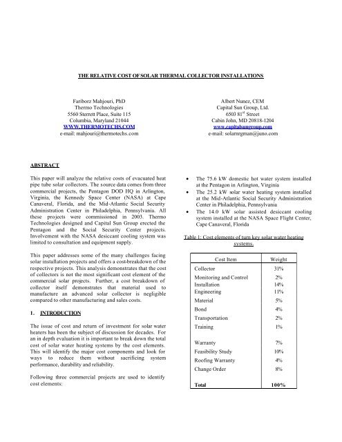
Table 1: <strong>Cost</strong> elements <strong>of</strong> turn key solar water heating<br />
systems.<br />
<strong>Cost</strong> Item<br />
Weight<br />
<strong>Collector</strong> 31%<br />
Monitoring and Control 2%<br />
<strong>Installation</strong> 14%<br />
Engineering 11%<br />
Material 5%<br />
Bond 4%<br />
Transportation 2%<br />
Training 1%<br />
Warranty 7%<br />
Feasibility Study 10%<br />
Ro<strong>of</strong>ing Warranty 4%<br />
Change Order 8%<br />
Total 100%
<strong>The</strong> collector and control system accounts for 1/3 <strong>of</strong> the<br />
total cost followed by installation costs.<br />
2. THE EVACUATED HEAT PIPE COLLECTORS<br />
production. <strong>The</strong>rmomax's engineering factory, in northern<br />
Italy, is involved in manufacturing the unique and<br />
sophisticated equipment needed for production and special<br />
components.<br />
<strong>The</strong> evacuated heat pipe solar collector is the result <strong>of</strong><br />
extensive research, development and testing. <strong>The</strong> resulting<br />
product is a high performance, reliable and cost effective<br />
solar collector that uses advance manufacturing<br />
technologies and materials.<br />
Figure 3: Quality and performance <strong>of</strong> evacuated heat pipe<br />
tubes are monitored through infrared imagining.<br />
Figure 1: Evacuated heat pipe collectors are manufactured<br />
in state-<strong>of</strong>-the art automated plants.<br />
<strong>The</strong>rmomax's manufacturing operations are geared to<br />
volume production and high quality assurance. Based on<br />
two locations in the United Kingdom, and a unit in Italy,<br />
<strong>The</strong>rmomax occupies over 10,000 m 2 <strong>of</strong> space for<br />
administration <strong>of</strong>fices, production plants, a development<br />
laboratory and testing facilities.<br />
In general, the product costs are categorized as fixed and<br />
variable costs. <strong>The</strong> elements <strong>of</strong> fixed costs are:<br />
• Factory Overhead (rent, insurance, depreciation,<br />
maintenance, R&D)<br />
• Selling and Distribution (salaries, commissions,<br />
promotions, advertising, insurance, depreciation)<br />
• Administration Expenses (salaries, pension,<br />
insurance, <strong>of</strong>fice supplies, accounting, marketing,<br />
cleaning, telephone and postage)<br />
• Warranty<br />
Figure 2: Production lines <strong>of</strong> evacuated heat pipe collectors<br />
are fully automated with specialized tooling for efficient and<br />
consistent high quality.<br />
<strong>The</strong> plants are equipped with modern machinery and<br />
specialized tooling for high volume efficient and reliable<br />
Figure 4: Over 53% <strong>of</strong> vacuum tube production costs are<br />
fixed. Tooling, machinery, factory overhead and<br />
administration expenses do not change with production<br />
output.<br />
Raw material costs are much higher than the labor expenses<br />
in the fully automated vacuum tube solar collector plant as
shown in Figure 4 and are thus subject to material markets<br />
fluctuation. But raw materials are not the major cost<br />
contributor <strong>of</strong> the finished product.<br />
<strong>The</strong> microprocessor based solar thermal controllers are<br />
sophisticated yet easy to operate. <strong>The</strong>y display the status <strong>of</strong><br />
solar system on their own LCD or on the screen <strong>of</strong> a<br />
computer. <strong>The</strong> principle is simple; they measure<br />
temperatures at the collector and storage tank. <strong>The</strong><br />
difference is calculated and is used to record energy gain<br />
(BTU meter function) and to operate the circulation pump<br />
(delta T controller function).<br />
Figure 5: <strong>The</strong> labor force in a state-<strong>of</strong>-the art solar<br />
manufacturing facility consists <strong>of</strong> highly skilled pr<strong>of</strong>essional<br />
staffs who monitor the production lines and maintain<br />
computerized machinery and tools.<br />
<strong>The</strong> heavy investment in modern machinery that contributes<br />
significantly to the unit cost <strong>of</strong> the collector is distributed<br />
among the total number <strong>of</strong> units produced. Variable costs<br />
start to dictate the unit cost once the production volume<br />
approaches the optimum facility capacity. At this point, the<br />
cost <strong>of</strong> raw material starts to plays a role in the final<br />
production cost. <strong>The</strong> cost reduction effect <strong>of</strong> increased<br />
production volume is shown in Figure 6.<br />
Unit <strong>Cost</strong><br />
600<br />
500<br />
400<br />
300<br />
200<br />
100<br />
0<br />
0 500 1000 1500 2000 2500<br />
Number <strong>of</strong> Units per Day<br />
Figure 6: <strong>The</strong>rmomax manufacturing facility is the world’s<br />
most modern and Europe’s largest solar vacuum tube plant.<br />
At full capacity it produces 2500 tubes in an eight-hour<br />
shift.<br />
3. CONTROL AND MONITORING SYSTEMS<br />
<strong>The</strong> brain <strong>of</strong> a solar system is its control and monitoring<br />
systems. It accounts for about 2% <strong>of</strong> the total costs <strong>of</strong> the<br />
system as shown in Table 1.<br />
Figure 7. SMT 500 controller records collected solar energy<br />
every 10 minutes in its internal memory while managing the<br />
optimum operation <strong>of</strong> the solar system. This data can be<br />
viewed on units LCD or downloaded to a computer for<br />
further analysis.<br />
To avoid overheating, the controller can be programmed to<br />
stop the circulation pump. <strong>The</strong> pump stops if the collector or<br />
tank temperature reaches the programmable high limit<br />
temperature. To prevent freezing, the controller may be<br />
programmed to activate the solar loop pump and circulate<br />
heat transfer fluid or water in the loop while freeze<br />
conditions exist.<br />
Figure 8. SMT 500 monitors and records the collector and<br />
the tank temperatures <strong>of</strong> the solar system every 10 minutes.<br />
<strong>The</strong>y can be viewed on unit’s LCD or down loaded to a<br />
computer for further analysis.<br />
<strong>The</strong>se sophisticated controllers have a diagnostic screen that<br />
shows potential problems such as sensor breakdown or
circuit fault. A communication link allows the property<br />
manager to download and send all recorded data to the<br />
engineer for system performance analysis and evaluation.<br />
angle. <strong>The</strong>refore, installation <strong>of</strong> collector is without any ro<strong>of</strong><br />
penetration for the collector structural anchorage.<br />
4. INSTALLATION<br />
<strong>The</strong>rmomax collectors are modular. Manifolds with tube<br />
support rails (69 lbs.) and sets <strong>of</strong> ten tubes per carton (48<br />
lbs.) are packed in rugged corrugated boxes that meet all<br />
small package shipment weight, strength and dimensional<br />
requirements. <strong>The</strong>se cartons can typically be transported to<br />
their final ro<strong>of</strong> destination by buildings elevator or hoist.<br />
Figure 11: After all plumbing work is completed and leak<br />
test is conducted, vacuum tubes will be inserted.<br />
Figure 9. <strong>The</strong>rmomax collectors will be anchored on four<br />
Ballast blocks.<br />
Each leg <strong>of</strong> 30-tube manifold is bolted to ballast block with<br />
supplied stainless steel bolts and polymer anchors. Stainless<br />
steel racks and side rails are bolted to the collector front and<br />
back brackets. Tube supporting rails are positioned onto the<br />
side rails and secured with supplied stainless steel bolts and<br />
clips. Universal braces are bolted diagonally between rear<br />
struts as well as front and rear legs for reinforcement.<br />
Wind loading <strong>of</strong> installed system is very low because <strong>of</strong><br />
tabular nature <strong>of</strong> the assembled collector modules.<br />
Figure 10: Manifolds are assembled at the job site using<br />
stainless steel hardware.<br />
Four (4) 70 lbs. ballast blocks can handle up to 90-mph<br />
wind for a 30-tube system installation at 38 degrees tilt<br />
Figure 12: Tubes are delivered to the job site after pipe<br />
work is completed and system is switched to manual<br />
operation.<br />
After all plumbing work is complete; vacuum tube<br />
collectors (Figure 12) are delivered to the ro<strong>of</strong> in boxes <strong>of</strong><br />
10 tubes each. While the water loop circulation pump is
unning, tubes are unpacked and inserted through a rubber<br />
grommet into manifold and secured into the compression<br />
clamp copper chamber in super insulated header.<br />
5. SUMMARY<br />
This paper identifies cost elements <strong>of</strong> direct solar water<br />
heating systems and simplicity <strong>of</strong> solar water heating<br />
installation on commercial buildings with a hot water<br />
circulation loop. <strong>The</strong>se systems rely on several key design<br />
features. <strong>The</strong> diode function <strong>of</strong> heat-pipe, the superior<br />
insulation <strong>of</strong> evacuated tube, and active digital controls for<br />
successful operation and protection from freezing and<br />
overheating are all essential elements. Project participants<br />
are pleased with the relative ease <strong>of</strong> implementing this type<br />
<strong>of</strong> system and its total costs.<br />
<strong>The</strong> cost analysis shows that 37% <strong>of</strong> total project costs are<br />
logistic expenses. Only 33% <strong>of</strong> total cost goes towards<br />
collector and system instrumentation with 14% for<br />
installation and 5 % for the balance <strong>of</strong> the system.<br />
6. ACKNOWLEDGEMENTS<br />
Figure 13: <strong>Installation</strong> costs are 14% <strong>of</strong> the total vacuum<br />
tube system costs.<br />
Final inspection is conducted after all tubes are inserted to<br />
the manifolds. At this stage, the controller will be switched<br />
to automatic operation.<br />
<strong>The</strong> modularity and installation simplicity <strong>of</strong> <strong>The</strong>rmomax<br />
tubes minimizes the installation costs. <strong>The</strong> most difficult<br />
and time-consuming part <strong>of</strong> an installation typically is<br />
positioning <strong>of</strong> ballast blocks.<br />
<strong>The</strong> authors would like to thank Robert Billak (retired) <strong>of</strong><br />
the Pentagon Energy Office, John Broughton and Curt<br />
Iffinger <strong>of</strong> the NASA Energy Management Office, Robert<br />
Stiteler <strong>of</strong> Midatlantic Social Security Center, Ethan Chon<br />
and Renee Domurat <strong>of</strong> the General Services Administration<br />
for procurement <strong>of</strong> the system. Further thanks go to Anne<br />
Crawley and Dr. Andy Walker <strong>of</strong> the US Department <strong>of</strong><br />
Energy, Federal Energy Management Program and for<br />
supporting NREL staff with the feasibility study,<br />
procurement specifications and design review.