

A Broadband Interior Antenna of Planar Monopole Type in Handsets
A Broadband Interior Antenna of Planar Monopole Type in Handsets
A Broadband Interior Antenna of Planar Monopole Type in Handsets

Create successful ePaper yourself
Turn your PDF publications into a flip-book with our unique Google optimized e-Paper software.
IEEE ANTENNAS AND WIRELESS PROPAGATION LETTERS, VOL. 4, 2005 9<br />
A <strong>Broadband</strong> <strong>Interior</strong> <strong>Antenna</strong> <strong>of</strong> <strong>Planar</strong> <strong>Monopole</strong><br />
<strong>Type</strong> <strong>in</strong> <strong>Handsets</strong><br />
Yong-Sun Sh<strong>in</strong>, Seong-Ook Park, and Manjai Lee, Member, IEEE<br />
Abstract—A novel <strong>in</strong>ternal antenna <strong>of</strong> planar monopole type<br />
is presented for broadband applications. The proposed antenna<br />
fed by a 50- microstrip l<strong>in</strong>e covers the digital cordless system<br />
(DCS, 1710–1880 MHz), personal communication system (PCS,<br />
1750–1870 MHz), and <strong>in</strong>ternational mobile telecommunication<br />
(IMT-2000, 1885–2200 MHz) bands with<strong>in</strong> S 11 10 dB. The<br />
antenna occupies a compact volume <strong>of</strong> 20 17 4.7 mm 3 and<br />
it is suitable to be built-<strong>in</strong> with<strong>in</strong> the hous<strong>in</strong>g <strong>of</strong> a mobile phone.<br />
The bandwidth <strong>of</strong> the proposed antenna (VSWR 2) has<br />
740 MHz start<strong>in</strong>g from 1620 to 2360 MHz. The IE3D s<strong>of</strong>tware and<br />
microwave studio (MWS) simulation are employed for optimiz<strong>in</strong>g<br />
the design parameters, and the simulation results are <strong>in</strong> agreement<br />
with those <strong>of</strong> the measured one, consider<strong>in</strong>g each associated case<br />
<strong>of</strong> the antenna itself, phone case, and battery.<br />
Index Terms—<strong>Broadband</strong>, <strong>in</strong>terior antenna, mobile antenna,<br />
planar monopole.<br />
I. INTRODUCTION<br />
WITH the rapid growth <strong>of</strong> mobile communications there is<br />
several grow<strong>in</strong>g demands with handset design requirements<br />
for small, lightweight, multifunction, and multiband. At<br />
the same time, the mobile handset adapts popularly the <strong>in</strong>ternal<br />
antenna structure also. Therefore, these demands for wireless<br />
term<strong>in</strong>al are an explosive issue.<br />
The planar monopole antenna is a good candidate for wireless<br />
communication because <strong>of</strong> its simple structure, omni-directional<br />
radiation characteristic, low pr<strong>of</strong>ile, and lightweight<br />
<strong>in</strong>ternal antenna [1]. In the previous researches, the impedance<br />
bandwidth <strong>of</strong> the planar monopole antenna has been <strong>in</strong>creased<br />
by several techniques such as modify<strong>in</strong>g geometries <strong>of</strong> bow-tie<br />
and trapezoidal shapes [2], [3], add<strong>in</strong>g a parasitic element [4],<br />
and thicken<strong>in</strong>g the radiator. In addition, it is important to consider<br />
the mobile phone case and battery because resonant frequency<br />
and impedance bandwidth are changed by the effect <strong>of</strong><br />
them [5].<br />
This paper presents a novel <strong>in</strong>ternal antenna <strong>of</strong> the planar<br />
monopole type for application <strong>in</strong> mobile phones. The bandwidth<br />
is improved by apply<strong>in</strong>g the trapezoidal feed<strong>in</strong>g shape and<br />
tilt<strong>in</strong>g it [2], [6]. The proposed antenna size has a small volume<br />
<strong>of</strong> 20 17 4.7 mm which <strong>in</strong>cludes the supporter and it can<br />
achieve a broad bandwidth <strong>of</strong> about 740 MHz capable <strong>of</strong> operat<strong>in</strong>g<br />
the digital cordless system (DCS, 1710–1880 MHz), personal<br />
communication system (PCS, 1750–1870 MHz), and<br />
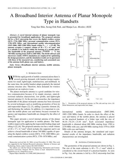
Fig. 1. Geometries <strong>of</strong> the proposed antenna. (a) The side and top views. (b)<br />
Detail dimensions and trapezoidal feed shape.<br />
<strong>in</strong>ternational mobile telecommunication (IMT-2000,<br />
1885–2200 MHz) bands. In order to check the effect <strong>of</strong> the<br />
case and battery <strong>of</strong> the mobile phone, the antenna is placed<br />
on the practical handsets <strong>of</strong> a folder type with the size <strong>of</strong><br />
46.16 92.24 21.64 mm . Each associated impedance<br />
bandwidth is obta<strong>in</strong>ed about 680 MHz start<strong>in</strong>g from 1590 to<br />
2270 MHz with case, and 450 MHz start<strong>in</strong>g from 1570 to 2020<br />
MHz with case and battery.<br />
Details <strong>of</strong> the antenna designs, the simulated and experimental<br />
results <strong>of</strong> the impedance bandwidth, and radiation<br />
characteristics are <strong>in</strong>vestigated.<br />
Manuscript received July 20, 2004; revised November 19, 2004. This work<br />
was supported by the National Research Laboratory, M<strong>in</strong>istry <strong>of</strong> Science and<br />
Technology, Korea, under Contract M1-0203-00-0015.<br />
The authors are with the School <strong>of</strong> Eng<strong>in</strong>eer<strong>in</strong>g, Information and Communications<br />
University, Daejeon 305-714, Korea (e-mail: sh<strong>in</strong>turtle@icu.ac.kr;<br />
sopark@icu.ac.kr; manjai@icu.ac.kr).<br />
Digital Object Identifier 10.1109/LAWP.2004.841623<br />
II. ANTENNA CONFIGURATION<br />
The geometries <strong>of</strong> the proposed antenna are shown <strong>in</strong> Fig. 1.<br />
The size <strong>of</strong> the ma<strong>in</strong> substrate is 40 75 1mm which is<br />
considered as the circuit board <strong>of</strong> a practical handset. As seen<br />
<strong>in</strong> Fig. 1(a), the antenna is fed by a 50- microstrip feed l<strong>in</strong>e<br />
1536-1225/$20.00 © 2005 IEEE
10 IEEE ANTENNAS AND WIRELESS PROPAGATION LETTERS, VOL. 4, 2005<br />
Fig. 5.<br />
Measured return losses consider<strong>in</strong>g hand phone case and battery.<br />
Fig. 2. The case and battery <strong>of</strong> the practical mobile phone [model: SPH-X8300<br />
anycall <strong>in</strong>tenna (Samsung)].<br />
Fig. 3.<br />
Measured and simulated return losses <strong>of</strong> only antenna.<br />
Fig. 4.<br />
Simulated current distribution at 1800 MHz.<br />
Fig. 6. Measured and simulated results <strong>of</strong> the return losses. (a) Return losses<br />
with case. (b) Return losses with case and battery.<br />
which consists <strong>of</strong> a metal strip width <strong>of</strong> 1.68 mm. In order to<br />
achieve the broad bandwidth, the feed which is connected between<br />
the microstrip l<strong>in</strong>e and antenna is a trapezoidal shape with<br />
a tilted angle <strong>of</strong> 34.7 <strong>in</strong> Fig. 1(b). By adjust<strong>in</strong>g the width <strong>of</strong><br />
the bottom and top side <strong>of</strong> a trapezoidal feed, the<br />
broad bandwidth can be achieved [2] due to the tilt<strong>in</strong>g copper
SHIN et al.: BROADBAND INTERIOR ANTENNA OF PLANAR MONOPOLE TYPE IN HANDSETS 11<br />
Fig. 7.<br />
Measured and simulated radiation patterns <strong>of</strong> the proposed antenna at 1800 MHz. (a) x-z plane (1800 MHz). (b) x-y plane (1800 MHz).<br />
Fig. 8.<br />
Measured and simulated radiation patterns consider<strong>in</strong>g phone case. (a) x-z plane (1800 MHz). (b) x-y plane (1800 MHz).<br />
plate. Also, the resonant frequency can be shifted lower because<br />
the travel<strong>in</strong>g current path is longer. As a result, the broad<br />
bandwidth can be achieved. The antenna is placed on a supporter<br />
with a height <strong>of</strong> 4.5 mm which has relative permittivity<br />
. As seen <strong>in</strong> Fig. 1(b), the basis <strong>of</strong> the proposed antenna<br />
is a planar monopole type <strong>of</strong> three pieces <strong>of</strong> copper strip<br />
with the dimensions <strong>of</strong> 20 17 0.2 mm which occupies a<br />
small volume <strong>in</strong> handsets. Fig. 2 shows the fabricated antenna<br />
mounted on the practical mobile phone with the dimensions <strong>of</strong><br />
46.16 92.24 21.64 mm . The antenna is designed <strong>in</strong> the real<br />
operat<strong>in</strong>g environment with the handset case and battery. Because<br />
the presence <strong>of</strong> the handset case and battery can alter the<br />
resonant frequency and radiation patterns, this paper <strong>in</strong>cludes<br />
their effects for antenna analysis. In order to f<strong>in</strong>d the optimized<br />
antenna characteristics, microwave studio (MWS) is used to<br />
tune each associated parameter <strong>of</strong> antenna structure. Fabrication<br />
and measured results were compared with the simulated ones.<br />
III. RESULTS<br />
The designed antenna has fabricated and measured with an<br />
Agilent 8510C network analyzer to confirm its performance.<br />
Fig. 3 shows the measured and simulated results <strong>of</strong> the antenna<br />
without consider<strong>in</strong>g the case and battery which resonates at<br />
1810 MHz with the bandwidth 41.1% at . In order<br />
to check the current flows at the resonance frequency, the simulation<br />
result <strong>in</strong> Fig. 4 is obta<strong>in</strong>ed from the IE3D s<strong>of</strong>tware.<br />
There are two current paths <strong>in</strong> Fig. 4 correspond<strong>in</strong>g to the upper<br />
branch and lower branch at the resonance frequency <strong>of</strong> 1800<br />
MHz. These total lengths <strong>of</strong> the current paths are about 41.5 mm
12 IEEE ANTENNAS AND WIRELESS PROPAGATION LETTERS, VOL. 4, 2005<br />
Fig. 9.<br />
Measured and simulated radiation patterns consider<strong>in</strong>g phone case and battery. (a) x-z plane (1800 MHz). (b) x-y plane (1800 MHz).<br />
IV. CONCLUSION<br />
TABLE I<br />
THE SIMULATED AVERAGE GAINS IN THREE PRINCIPAL PLANES<br />
and 44.2 mm, which are correspond<strong>in</strong>g to an approximately<br />
quarter-wavelength at 1700 and 1800 MHz, respectively.<br />
Fig. 5 shows the measured return losses consider<strong>in</strong>g the antenna<br />
itself, phone case, and battery. Fig. 6 shows the measured<br />
and simulated return losses <strong>in</strong> cases consider<strong>in</strong>g the hand<br />
phone case and battery. As shown <strong>in</strong> Fig. 6, the resonated frequency<br />
is shifted by the presence <strong>of</strong> case and battery. Each associated<br />
bandwidth has 680 MHz (1590–2270 MHz) with case<br />
and 450 MHz (1570–2020 MHz) with case and battery. The simulation<br />
results are performed with MWS. The experimental results<br />
have a good agreement with the simulated results. Fig. 7<br />
shows the measured and simulated radiation patterns <strong>of</strong> the antenna<br />
itself at the frequency <strong>of</strong> 1800 MHz. It is seen that the<br />
radiation patterns are approximately omnidirectional and similar<br />
to those <strong>of</strong> a z-directed electric monopole. Table I shows the<br />
simulated average ga<strong>in</strong>s <strong>in</strong> three pr<strong>in</strong>cipal planes. The measured<br />
maximum ga<strong>in</strong> has 2.3 dBi, while the simulated maximum ga<strong>in</strong><br />
has 2.54 dBi at 1800 MHz.<br />
Figs. 8 and 9 show the radiation patterns <strong>of</strong> the antenna with<br />
the placement <strong>of</strong> case and battery, respectively. The measured<br />
maximum ga<strong>in</strong> is about 2.8 dBi with case and 3.1 dBi with case<br />
and battery, while the simulated maximum ga<strong>in</strong> has 2.98 and<br />
3.2 dBi at 1800 MHz, respectively. This slight discrepancy can<br />
be attributed to the effects <strong>of</strong> the conductor loss and dielectric<br />
loss <strong>of</strong> case, battery, and other conductors <strong>in</strong> the mobile phone.<br />
The characteristics <strong>of</strong> the broad bandwidth and omnidirectional<br />
radiation patterns are very suitable for handset application.<br />
A novel <strong>in</strong>ternal antenna <strong>of</strong> planar monopole type suitable<br />
for DCS, PCS, and IMT-2000 bands has been proposed and <strong>in</strong>vestigated.<br />
In addition, the antenna is applied to the practical<br />
handsets. The proposed antenna has a compact dimension <strong>of</strong><br />
20 17 4.7 mm and when it is considered case and battery <strong>in</strong><br />
practical handsets, further reduction size <strong>of</strong> the antenna is possible.<br />
Also, if the slot which has the taped shape <strong>of</strong> edges is<br />
added <strong>in</strong> the center from the feed part with a trapezoidal shape<br />
to each branch <strong>of</strong> prototype antenna, the global system for mobile<br />
(880–960 MHz) band can be achieved.<br />
The obta<strong>in</strong>ed bandwidth is 740 MHz at<br />
and the<br />
measured maximum ga<strong>in</strong> is 2.3 dBi without consider<strong>in</strong>g the battery<br />
and handset case. Each associated bandwidth is 680 MHz<br />
(1590–2270 MHz) with case and 450 MHz (1570–2020 MHz)<br />
with case and battery at<br />
and the maximum ga<strong>in</strong>s<br />
are 2.8 and 3.1 dBi, respectively. The omnidirectional radiation<br />
patterns are similar to those <strong>of</strong> the monopole antenna. These features<br />
make the proposed antenna attractive for mobile handsets.<br />
REFERENCES<br />
[1] P. L. Teng and K. L. Wong, “<strong>Planar</strong> monopole folded <strong>in</strong>to a compact<br />
structure for very low pr<strong>of</strong>ile multiband mobile phone antenna,” Microw.<br />
Opt. Technol. Lett., vol. 33, no. 1, pp. 22–25, Apr. 2002.<br />
[2] Z. N. Chen and Y. W. M. Chia, “Impedance characteristics <strong>of</strong> trapezoidal<br />
planar monopole antennas,” Microw. Opt. Technol. Lett., vol. 27, no. 2,<br />
pp. 120–122, Oct. 2000.<br />
[3] Z. N. Chen, “Impedance characteristics <strong>of</strong> planar bow-tie-like monopole<br />
antennas,” Electron. Lett., vol. 36, no. 13, pp. 1100–1101, Jun. 2000.<br />
[4] X. Jiang, S. Li, and G. Su, “<strong>Broadband</strong> planar antenna with parasitic<br />
radiator,” Electron. Lett., vol. 39, no. 23, pp. 1626–1627, Nov. 2003.<br />
[5] O. Kivekas, J. Ollika<strong>in</strong>en, T. Leht<strong>in</strong>iemi, and P. Va<strong>in</strong>ika<strong>in</strong>en, “Bandwidth,<br />
SAR, and efficiency <strong>of</strong> <strong>in</strong>ternal mobile phone antennas,” IEEE<br />
Trans. Electromagn. Compat., vol. 46, no. 1, pp. 71–86, Feb. 2004.<br />
[6] M. J. Ammann and Z. N. Chen, “A wide-band shorted planar monopole<br />
with bevel,” IEEE Trans. <strong>Antenna</strong>s Propag., vol. 51, no. 4, pp. 901–903,<br />
Apr. 2003.


