C:\Documents and Settings\Allen - MSAWorld.com
C:\Documents and Settings\Allen - MSAWorld.com
C:\Documents and Settings\Allen - MSAWorld.com

Create successful ePaper yourself
Turn your PDF publications into a flip-book with our unique Google optimized e-Paper software.
ELECTROLUX MAJOR APPLIANCES OF NORTH AMERICA<br />
SERVICE MANUAL<br />
Commercial Dryers<br />
Gas & Electric<br />
Models<br />
White-Westinghouse<br />
5995468310 September 2006<br />
1
SAFE SERVICING PRACTICES - ALL APPLIANCES<br />
To avoid personal injury<strong>and</strong>/or propertydamage, it is important that SafeServicing<br />
Practices be observed. The following are some limited examples of safe practices:<br />
1. DO NOT attempt a product repair if you have any doubts as to your ability to<br />
<strong>com</strong>plete it in a safe <strong>and</strong> satisfactory manner.<br />
2. Before servicing or moving an appliance:<br />
• Remove the power cord from the electrical outlet, trip the circuit breaker to the<br />
OFF position, or remove the fuse.<br />
• Turn off the gas supply.<br />
• Turn off the water supply.<br />
3. Never interfere with the proper operation of any safety device.<br />
4. USE ONLY REPLACEMENT PARTS CATALOGED FOR THIS APPLIANCE.<br />
SUBSTITUTIONS MAY DEFEAT COMPLIANCE WITH SAFETY<br />
STANDARDS SET FOR HOME APPLIANCES.<br />
5. GROUNDING: The st<strong>and</strong>ard color coding for safety ground wires is GREEN, or<br />
GREEN with YELLOW STRIPES. Ground leads are not to be used as current<br />
carrying conductors. It is EXTREMELY important that the service technician<br />
reestablish all safety grounds prior to <strong>com</strong>pletion of service. Failure to do so will<br />
create a hazard.<br />
6. Prior to returning the product to service, ensure that:<br />
• All electrical connections are correct <strong>and</strong> secure<br />
• All electrical leads are properlydressed <strong>and</strong> secured awayfrom sharp edges,<br />
high-temperature <strong>com</strong>ponents, <strong>and</strong> movingparts<br />
• Allnon-insulatedelectricalterminals,connectors,heaters,etc.areadequately<br />
spaced away from all metal parts <strong>and</strong> panels<br />
• All safety grounds (both internal <strong>and</strong> external) are correctly <strong>and</strong> securely<br />
connected<br />
• All panels are properly <strong>and</strong> securely reassembled<br />
ATTENTION!!!<br />
This service manual is intended for use by persons having electrical <strong>and</strong> mechanical<br />
training <strong>and</strong> a level of knowledge of these subjects generally considered acceptable in the<br />
appliance repair trade. Electrolux Home Products cannot be responsible, nor assume any<br />
liability, for injury or damage of any kind arising from the use of this manual.<br />
© 2006 Electrolux Major Appliances of North America<br />
2
SAFE SERVICING PRACTICES 2<br />
QUICK REFERENCE SHEET 6<br />
Serial nameplate location 6<br />
Serial number breakdown 6<br />
Wiring diagram location 6<br />
Specification 7<br />
Component resistance chart 8<br />
Sample wiring diagram for electric models 9<br />
Sample wiring diagram for gas models 10<br />
SECTION A- INSTALLATION INSTRUCTIONS GAS & ELECTRIC DRYER 11 - 21<br />
What to do if you smell gas 11<br />
Pre-installation requirements 12<br />
Tools <strong>and</strong> materials required for installation 12<br />
Electrical requirements 12<br />
Electric dryer 12<br />
Circuit 12<br />
Power supply 12<br />
Power supply cord kit 12<br />
Outlet receptacle 12<br />
Gas dryer 12<br />
Circuit 12<br />
Power supply 12<br />
Power supply cord 12<br />
Exhaust system requirements 12<br />
Exhaust direction 14<br />
Exhaust duct locating dimensions 14<br />
Gas supply requirements 14<br />
Location of your dryer 14<br />
Do not install your dryer 14<br />
Insulation in a recess closet 14<br />
Minimum installation clearances 15<br />
Rough-in dimensions 16<br />
Unpacking 16<br />
Reversing door swing 16<br />
To change the direction of the door opening 16<br />
Electrical installation 17<br />
All electric dryers 17<br />
Grounding requirements 17<br />
Electric dryers 17<br />
All gas dryers 17<br />
Electrical connection for 3-wire system (Electric dryer) 18<br />
Electrical connection for 4-wire system (Electric dryer) 18<br />
Installation 19<br />
Gas connection 19<br />
Replacement parts 19<br />
Lint blade retaining pin location <strong>and</strong> orientation 20<br />
Commercial appliance warranty information 21<br />
Changing the vend price on a Greenwald V-8 coin chute 22<br />
Changing the price of a V-8 coin chute ID# 20-3000 22<br />
Changing the price of a V-8 coin chute ID# 20-3020 23<br />
Parts list for Greenwald V-8 coin chutes 24<br />
Meter case instructions <strong>and</strong> parts list 25<br />
Parts list for Greenwald dryer timers 25<br />
SECTION B - OPERATION 26 - 39<br />
Coin box 26<br />
Coin drawer 26<br />
Coin chute 26<br />
3
Meter case timer (accumulator) 28<br />
Dryer section 31<br />
Drum 31<br />
Heat source 31<br />
Electric 31<br />
Gas 31<br />
Drive motor <strong>and</strong> blower 31<br />
Control thermostat 31<br />
Start switch 32<br />
Temperature switch 32<br />
Airflow 33<br />
Airflow electric dryers 33<br />
Airflow gas dryers 34<br />
Airflow problems 34<br />
Restrictions 34<br />
Air leaks 35<br />
Short unrestricted vents 35<br />
Electrical operation (Electric dryers models) 35<br />
Accumulator (timer)circuit 35<br />
Drive motor circuit 36<br />
Control thermostat/fabric selector switch circuit 36<br />
Heating circuit 37<br />
Drying time 37<br />
Electrical operation (gas dryers models) 37<br />
Accumulator (timer)circuit 38<br />
Drive motor circuit 38<br />
Control thermostat/fabric selector switch circuit 38<br />
Heating circuit 38<br />
Drying time 39<br />
SECTION C - TROUBLESHOOTING 40 - 42<br />
Coin slide will not push in 40<br />
Coin slide will not push in all the way 40<br />
Dryer are will not start 40<br />
Dryer runs, but indicator light does not glow 40<br />
Dryer does not shut off at the end of the cycle 40<br />
Dryer runs as long as the start switch is held in 41<br />
Drivemotor runs, but dryer does not heat (electric dryer) 41<br />
The dryer operates on high heat, when the fabric<br />
selector switch is set to medium or low 41<br />
The drivemotor runs, but that drum does not turn 41<br />
The dryer overheats 41<br />
Drivemotor runs, but dryer does not heat (gas dryer) 42<br />
SECTION D - TEARDOWN 43 - 70<br />
Removing the meter case mechanism cover 43<br />
Removing the meter case mechanism cover latch 43<br />
Removing the meter case mechanism cover locking mechanism 43<br />
Removing the coin drawer 44<br />
Removing the coin drawer face <strong>and</strong> locking mechanism 44<br />
Removing the coin chute 45<br />
Disassembling the coin chute 46<br />
Removing the accumulator (timer) 50<br />
Removing the accumulator mounting bracket 51<br />
Removing switch A <strong>and</strong> B 51<br />
Removing accumulator motor 52<br />
Removing drive <strong>and</strong> switch cams 52<br />
Removing timing cam 52<br />
4
Removing temperature knob 53<br />
Removing The Loading Door 53<br />
Separating the loading door panels 53<br />
Removing door strike 53<br />
Removing door seal 54<br />
Removing door h<strong>and</strong>le 54<br />
Removing door hinges 55<br />
Removing lint screen 55<br />
To raise the front of the top panel 55<br />
To remove the top panel <strong>and</strong> coin box 56<br />
Removing the coin box 57<br />
Removing the gasket between the coin box <strong>and</strong> the top panel 57<br />
Removing the holddown bolt 57<br />
Removing the holddown bar 57<br />
Removing the door switch 57<br />
Removing the temperature switch 58<br />
Removing the indicator light 58<br />
Removing the front panel 58<br />
Removing the console 59<br />
Removing the console frame 59<br />
Removing the start button 59<br />
Removing the start switch 60<br />
Removing the door catch 60<br />
Removing the door vent grill 60<br />
Replacing the front panel air duct 60<br />
Replacing the felt seal 61<br />
Replacing the foam seal 61<br />
Removing the rear access panel 61<br />
Releasing the dryer belt 61<br />
Removing the vane from the drum 62<br />
Removing the drum 62<br />
Removing the belt 62<br />
Removing the hitch ball from the drum 63<br />
Removing the teflon glides 63<br />
Removing the drum heat shield (electric dryers) 63<br />
Removing the ball hitch support 63<br />
Removing the high limit thermostat 64<br />
Removing the thermal limiter (electric dryers) 64<br />
Removing the heating element assembly (electric dryers) 64<br />
Removing the control thermstat 65<br />
Removing the blower housing <strong>and</strong> fan blade 65<br />
Removing the idler pulley 65<br />
Removing the idler pulley assembly 66<br />
Removing the drive motor 66<br />
Removing the burner (gas dryers) 66<br />
Removing the ignitor (gas dryers) 67<br />
Removing the gas valve assembly (gas dryers) 67<br />
Removing the gas valve coils (gas dryers) 68<br />
Removing the sensor (gas dryers) 68<br />
Removing the <strong>com</strong>bustion chamber (gas dryers) 68<br />
Removing the duct <strong>and</strong> heat shield (gas dryers) 68<br />
Removing the manifold pipe (gas dryers) 69<br />
Removing the vent pipe (gas dryers) 69<br />
Removing the gasket between the vent pipe <strong>and</strong> blower housing 69<br />
5
QUICK REFERENCE SHEET<br />
1. Serial nameplate location: on the front<br />
panel at the left side of the dryer door<br />
opening.<br />
2. Serial number breakdown.<br />
X D 6 0 4 0 2 2 4 7<br />
Incremented unit number<br />
Production week<br />
Last digit of production year<br />
Product identification<br />
Manufacturing Facility<br />
3. Wiring diagram location:<br />
On the right-h<strong>and</strong>bodyside inside rear<br />
access panel.<br />
6
QUICK REFERENCE SHEET<br />
SPECIFICATION<br />
Electrical<br />
Volts 120/208 or 120/240<br />
Amps (circuit)<br />
Motor wattage<br />
Heat input (Watts @ 208/240 VAC)<br />
Heat input (BTU/Hr.)<br />
Auto. Elec. Ignition<br />
Drum<br />
Size (Cu. Ft.)<br />
Finish<br />
R.P.M.<br />
Airflow CFM<br />
DRUM TEMPERATURES (Max.<br />
opening on 1st cycle)<br />
High<br />
Medium<br />
Low<br />
ELECTRIC MODELS<br />
120/208 or 120/240<br />
30<br />
160-350 Watts<br />
3200/4500<br />
---<br />
---<br />
5.75<br />
Powder Paint Epoxy<br />
48 - 54<br />
200<br />
134° - 180°<br />
130° - 170°<br />
120° - 165°<br />
GAS MODELS<br />
120<br />
15<br />
160-350 Watts<br />
---<br />
20,000<br />
Yes<br />
5.75<br />
Powder Paint Epoxy<br />
48 - 54<br />
200<br />
140° - 180°<br />
130° - 170°<br />
120° - 165°<br />
Dimension (Inches)<br />
Height<br />
Width<br />
Depth<br />
Vent Capability**<br />
Top Finish<br />
Port Opening (Sq. In.)<br />
43 5/8”<br />
26 7/8”<br />
25.5”<br />
4-Way<br />
Powder Paint Enamel<br />
235<br />
43 5/8”<br />
26 7/8”<br />
25.5”<br />
3-Way<br />
Powder Paint Enamel<br />
235<br />
** Electric dryers can be vented four ways: through back, bottom, right or left side.<br />
** Gas dryers can be vented three ways: through back, bottom, or right side.<br />
±<br />
±<br />
±<br />
±<br />
±<br />
7
QUICK REFERENCE SHEET<br />
Component Resistances*<br />
Electric Models<br />
Gas Models<br />
Drive motor (120 volt, 60 Hz, 1/4 h.p. 1725 rpm)<br />
Motor Start Winding<br />
Motor Run Winding<br />
Heating Element<br />
4.5 Ohms<br />
3.8 Ohms<br />
12.8 Ohms<br />
4.5 Ohms<br />
3.8 Ohms<br />
Burner Assembly<br />
Ignitor<br />
Secondary Coil<br />
Booster Coil<br />
---<br />
---<br />
---<br />
50 - 400 Ohms<br />
1200 Ohms<br />
1320 Ohms<br />
* +/- 10% @ 77° F<br />
8
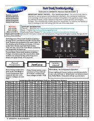
SAMPLE WIRING DIAGRAM FOR ELECTRIC MODELS<br />
CAUTION: DISCONNECT ELECTRIC CURRENT BEFORE SERVICING. LABELALL WIRES PRIOR TO<br />
DISCONNECTION WHEN SERVICING CONTROLS. WIRING ERRORS CAN CAUSE IMPROPERAND<br />
DANGEROUS OPERATION. VERIFY PROPER OPERATION AFTER SERVICING.<br />
L1<br />
240 VAC<br />
120 VAC 120 VAC<br />
L2<br />
RED<br />
ACCUMULATOR<br />
TM<br />
BLUE<br />
BLUE<br />
CABINET<br />
BLUE<br />
N GRN<br />
WIRE NOT INCLUDED IN MODELS PROVIDED<br />
WITH 4 - WIRE POWER CORD.<br />
C NO<br />
DOOR SWITCH<br />
GRAY<br />
BLK<br />
6<br />
2<br />
RED<br />
A<br />
WHT<br />
WHT<br />
WHT<br />
THERMAL<br />
LIMITER<br />
WHT<br />
4<br />
START<br />
RUN<br />
MOTOR 5<br />
GRAY<br />
1<br />
GRN<br />
FABRIC SELECTOR<br />
SWITCH<br />
INDICATOR LIGHT<br />
YEL<br />
TAN<br />
TAN<br />
START SWITCH<br />
CABINET<br />
BASE<br />
YEL<br />
HEATER<br />
4500 WATTS<br />
B<br />
3 K 4 5 BLUE<br />
28K <br />
ORG/BLK<br />
BLK<br />
ORG<br />
CONTROL<br />
THERMOSTAT<br />
ORG/BLK<br />
SAFETY<br />
THERMOSTAT<br />
GRN<br />
GRN<br />
CABINET<br />
COIN BOX<br />
CABINET<br />
TOP PANEL<br />
1ACCUMULATION.<br />
DRIVE<br />
MOTOR<br />
HEATER<br />
NOTES:<br />
1. All wiring must conform to local electrical codes.<br />
2. Connect dryer to a 30 amp individual branch circuit.<br />
3. Motor at rest, thermostat closed <strong>and</strong> fabric<br />
selector switch at regular.<br />
WIRING CODES<br />
QUICK DISCONNECT TERMINALS<br />
CONNECTION<br />
NO CONNECTION<br />
MOTOR SWITCH<br />
SPLICE<br />
MOTOR PROTECTOR<br />
CHASSIS (CABINET) GROUND<br />
SCREW TERMINAL<br />
HARNESS CONNECTOR TERMINAL<br />
INSULATED TERMINAL<br />
TRANSIENT VOLT SUPPRESSOR<br />
FABRIC SELECTOR.<br />
SWITCH<br />
FUNCTION RESISTANCE <br />
HIGH<br />
INFINITY<br />
MEDIUM 3K +/-5%<br />
LOW 10 MAX<br />
9
SAMPLE WIRING DIAGRAM FOR GAS MODELS<br />
CAUTION: DISCONNECT ELECTRIC CURRENT BEFORE SERVICING. LABELALL WIRES PRIOR TO<br />
DISCONNECTION WHEN SERVICING CONTROLS. WIRING ERRORS CAN CAUSE IMPROPERAND<br />
DANGEROUS OPERATION. VERIFY PROPER OPERATION AFTER SERVICING.<br />
L1<br />
120 VAC<br />
N<br />
GRN<br />
GRN<br />
BLUE<br />
CABINET<br />
TOP PANEL<br />
ACCUMULATOR<br />
TM<br />
RED<br />
A<br />
RED<br />
BLUE<br />
WHT<br />
WHT<br />
DOOR SWITCH<br />
BLUE C NO<br />
INDICATOR LIGHT<br />
TAN<br />
WHT<br />
GRAY<br />
START<br />
SWITCH<br />
4<br />
GRAY<br />
6 2<br />
START<br />
GRN<br />
YELLOW<br />
TAN<br />
RUN<br />
MOTOR 5 1<br />
CABINET BASE<br />
YEL<br />
SENSOR<br />
IGNITER<br />
FABRIC SELECTOR<br />
SWITCH<br />
WHT WHT<br />
WHT<br />
WHT<br />
B<br />
ORG<br />
4 5<br />
2.4K <br />
BLUE<br />
7K <br />
CONTROL<br />
THERMOSTAT<br />
PINK<br />
PINK<br />
ORG<br />
SAFETY<br />
THERMOSTAT<br />
ORG<br />
SEC<br />
COIL<br />
HOLDING<br />
COIL<br />
BOOSTER<br />
COIL<br />
1ACCUMULATION.<br />
DRIVE<br />
MOTOR<br />
HEATER<br />
NOTES:<br />
1. All wiring must conform to local electrical codes.<br />
2. Connect dryer to a 15 amp individual branch circuit.<br />
3. Motor at rest, thermostat closed <strong>and</strong> fabric<br />
selector switch at regular.<br />
WIRING CODES<br />
QUICK DISCONNECT TERMINALS<br />
CONNECTION<br />
NO CONNECTION<br />
MOTOR SWITCH<br />
SPLICE<br />
MOTOR PROTECTOR<br />
CHASSIS (CABINET) GROUND<br />
SCREW TERMINAL<br />
HARNESS CONNECTOR TERMINAL<br />
INSULATED TERMINAL<br />
TRANSIENT VOLT SUPPRESSOR<br />
FABRIC SELECTOR.<br />
SWITCH<br />
FUNCTION RESISTANCE <br />
HIGH<br />
INFINITY<br />
MEDIUM 2.4K +/-5%<br />
LOW 10 MAX<br />
10
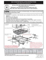
SECTION A - INSTALLATION INSTRUCTIONS GAS & ELECTRIC DRYER<br />
Before beginning installation, carefully read these instructions. This will simplify the installation <strong>and</strong> ensure the<br />
dryer is installed correctly <strong>and</strong> safely. Leave these instructions near the Dryer after installation for future reference.<br />
NOTE: The electrical service to the Dryer must conform with local codes <strong>and</strong> ordinances <strong>and</strong> the latest edition of<br />
the National Electrical Code, ANSI/NFPA 70, or in Canada, the Canadian electrical code C22.1 part 1.<br />
NOTE: The gas service to the Dryer must conform with local codes <strong>and</strong> ordinances <strong>and</strong> the latest edition of the<br />
National Fuel Gas Code ANSI Z223.1.<br />
For your safety the information in this manual must be followed to minimize<br />
the risk of fire or explosion or to prevent property damage, personal injury or loss of life.<br />
- Do not store or use gasoline or other flammable vapors <strong>and</strong> liquid in the vicinity of this<br />
or any other appliance.<br />
- WHAT TO DO IF YOU SMELL GAS<br />
· Do not try to light any appliance.<br />
· Do not touch any electrical switch; do not use any phone in your building.<br />
· Clear the room, building or area of all occupants.<br />
· Immediately call your gas supplier from a neighbor’s phone. Follow the gas supplier's<br />
instructions.<br />
· If you cannot reach your gas supplier, call the fire department.<br />
Installation must be performed by a qualified or licensed contractor, plumber, or gasfitter qualified<br />
or licensed by the state, province, or region where this appliance is being installed.<br />
11
PRE-INSTALLATION REQUIREMENTS<br />
Tools <strong>and</strong> Materials Required for Installation:<br />
OUTLET RECEPTACLE - NEMA 10-30R or NEMA 14-<br />
30R receptacle to be located so the power supply cord<br />
is accessible when the dryer is in the installed position<br />
1. Phillips head screwdriver.<br />
2. Channel-lock adjustable pliers.<br />
3. Carpenter's level.<br />
4. Flat or straight blade screwdriver.<br />
5. Duct tape.<br />
6. Rigid or flexible metal 4 inch (10.2 cm) duct.<br />
7. Vent hood.<br />
8. Pipe thread sealer (Gas).<br />
9. Plastic knife<br />
SUBJECT TO LOCAL<br />
REGULATIONS<br />
NEMA10-30R<br />
(COPPER)<br />
ELECTRICAL REQUIREMENTS<br />
ELECTRIC Dryer<br />
CIRCUIT - Individual 30 amp. branch circuit fused with<br />
30 amp. minimum time delay fuses or circuit breakers.<br />
POWER SUPPLY - 3 wire, 240 volt, single phase, 60<br />
Hz, Alternating Current.<br />
POWER SUPPLY CORD KIT - The dryerMUST employ<br />
a 3-conductor power supply cord NEMA 10-30 type<br />
SRDT rated at 240 volt AC minimum, 30 amp., with 3<br />
open end spade lug connectors with upturned ends or<br />
closed loop connectors <strong>and</strong> marked for use with clothes<br />
dryers. If being installed in a new branch circuit<br />
installation, manufactured (mobile) home, recreational<br />
vehicle or area which prohibits grounding through the<br />
neutral conductor, the dryerMUST employ a 4-conductor<br />
power supply cord NEMA 14-30 type SRDT or ST (as<br />
required) rated at 240 voltAC minimum, 30 amp., with 4<br />
open end spade lug connectors with upturned ends or<br />
closed loop connectors <strong>and</strong> marked for use with clothes<br />
dryers. See ELECTRICAL CONNECTIONS FOR A 4-<br />
WIRE SYSTEM.<br />
GAS Dryer<br />
CIRCUIT - Individual 15 amp. branch circuit fused with a<br />
15 amp. maximum time delay fuse or circuit breaker.<br />
POWER SUPPLY- 3 wire, 120 volt single phase, 60 Hz,<br />
Alternating Current.<br />
POWER SUPPLY CORD - The dryer is equipped with a<br />
120 volt 3-wire power cord.<br />
NOTE: Do not under<br />
any circumstances<br />
remove grounding<br />
prong from plug.<br />
GROUNDINGPRONG<br />
EXHAUST SYSTEM REQUIREMENTS<br />
Use only 4 inch (10.2 cm) diameter (minimum) rigid or<br />
flexiblemetal duct <strong>and</strong> approved vent hood which has a<br />
swing-out damper(s) that open when the dryer is in<br />
operation. When the dryer stops, the dampers<br />
automatically close to prevent drafts <strong>and</strong> the entrance of<br />
insects <strong>and</strong> rodents. To avoid restricting the outlet,<br />
maintain a minimum of 12 inches (30.5 cm) clearance<br />
between the vent hood <strong>and</strong> the ground or any other<br />
obstruction.<br />
12
The following are specific<br />
requirements for proper <strong>and</strong> safe operation of<br />
your dryer. Failure to follow these instructions<br />
can create excessive drying times <strong>and</strong> fire<br />
hazards.<br />
Do not use plastic flexible duct to exhaust the dryer.<br />
Excessive lint can build up inside exhaust system <strong>and</strong><br />
create a fire hazard <strong>and</strong> restrict air flow. Restricted air<br />
flow will increase dryer times. If your present system is<br />
made up of plastic duct or metal foil duct, replace it<br />
with a rigid or flexible metal duct. Ensure the present<br />
duct is free of any lint prior to installing dryer duct.<br />
If the dryer is not exhausted outdoors, some fine lint<br />
will be expelled into the laundry area. An accumulation<br />
of lint in any area of the home can create a health <strong>and</strong><br />
fire hazard. The dryer exhaust system MUST be<br />
exhausted to the outside of the dwelling!<br />
Do not allow <strong>com</strong>bustible materials (for example:<br />
clothing, draperies/curtains, paper) to <strong>com</strong>e in contact<br />
with exhaust system.The dryer MUST NOTbe exhausted<br />
into a chimney, a wall, a ceiling, or any concealed space<br />
of a building which can accumulate lint, resulting in a fire<br />
hazard.<br />
Exceeding the length of duct pipe or number of elbows<br />
allowed in the "MAXIMUM LENGTH" charts can cause<br />
an accumulation of lint in the exhaust system. Plugging<br />
the system could create a fire hazard, as well as increase<br />
drying times.<br />
Do not screen the exhaust ends of the vent system,<br />
nor use any screws or rivets to assemble the exhaust<br />
system. Lint can be<strong>com</strong>e caught in the screen, on the<br />
screws or rivets, clogging the duct work <strong>and</strong> creating a<br />
fire hazard as well as increasing drying times. Use an<br />
approved vent hood to terminate the duct outdoors, <strong>and</strong><br />
seal all joints with duct tape. All male duct pipe fittings<br />
MUST be installed downstream with the flow of air.<br />
Explosion hazard. Do not install the<br />
dryer where gasoline or other flammables are kept or<br />
stored. If the dryer is installed in a garage, it must be a<br />
minimum of 18 inches (45.7 cm) above the floor. Failure<br />
to do so can result in death, explosion, fire or burns.<br />
MAXIMUM LENGTH<br />
of 4” (10.2 cm) Dia. Rigid Metal Duct<br />
correct<br />
VENT HOOD TYPE<br />
(Preferred)<br />
Number<br />
Louvered<br />
of<br />
90°<br />
Turns 4”<br />
(10.2 cm)<br />
(6.35 cm)<br />
0 60 ft. (18.28 m) 48 ft.(14.63 m)<br />
1 52 ft. (15.84 m) 40 ft.(12.19 m)<br />
2 44 ft. (13.41 m) 32 ft. (9.75 m)<br />
3 32 ft. (9.75 m) 24 ft. (7.31 m)<br />
4 28 ft. (8.53 m) 16 ft. (4.87 m)<br />
Number<br />
of<br />
90°<br />
Turns<br />
MAXIMUM LENGTH<br />
of 4” (10.2 cm) Dia. Flexible Metal Duct<br />
VENT HOOD TYPE<br />
(Preferred)<br />
4”<br />
(10.2 cm)<br />
Louvered<br />
0 30 ft. (9.14 m) 18 ft. (5.49 m)<br />
1 22 ft. (6.71 m) 14 ft. (4.27 m)<br />
2 14 ft. (4.27 m) 10 ft. (3.05 m)<br />
3 NOT RECOMMENDED<br />
incorrect<br />
(6.35 CM)<br />
INSTALLMALE FITTINGS IN CORRECTDIRECTION<br />
In installations where the exhaust system is not<br />
described in the charts, the following method must be<br />
used to determine if the exhaust system is acceptable:<br />
1. Connect an inclined or digital manometer between<br />
the dryer <strong>and</strong> the point the exhaust connects to the<br />
dryer.<br />
2. Set the dryer temperature to low heat <strong>and</strong> start the<br />
dryer.<br />
3. Read the measurement on the manometer.<br />
13<br />
4. The system back pressure MUST NOT be higher<br />
than 0.75 or lower than .10 inches of water column.<br />
If the system back pressure is less than 0.75 inches<br />
<strong>and</strong> more than .10 inches of water column, the<br />
system is acceptable. If the manometer reading is
higher than 0.75 inches of water column, the system<br />
is too restrictive <strong>and</strong> the installation is unacceptable.<br />
Although vertical orientation of the exhaust system is<br />
acceptable, certain extenuating circumstances could<br />
affect the performance of the dryer:<br />
• Only the rigid metal duct work should be used.<br />
• Venting vertical through a roof may expose the<br />
exhaust system to down drafts causing an increase<br />
in vent restriction.<br />
• Running the exhaust system through an uninsulated<br />
area may cause condensation <strong>and</strong> faster<br />
accumulation of lint.<br />
• Compression or crimping of the exhaust system will<br />
cause an increase in vent restriction.<br />
The exhaust system should be inspected <strong>and</strong> cleaned a<br />
minimum of every 6 months with normal usage. The<br />
more the dryer is used, the more often you should check<br />
the exhaust system <strong>and</strong> vent hood for proper operation.<br />
EXHAUST DIRECTION<br />
All dryers shipped from the factory are set up for rear<br />
exhausting. However, on electric dryers, exhausting can<br />
be to the right or left side of the cabinet or the bottom<br />
of the dryer. On gas dryers, exhausting can be to the<br />
right side of the cabinet or the bottom of the dryer.<br />
Directional exhausting can be ac<strong>com</strong>plished by<br />
installing Exhaust Kit, P/N 131456800, available<br />
through your parts distributor. Follow the instructions<br />
supplied with the kit.<br />
EXHAUST DUCT LOCATING DIMENSIONS<br />
1. Installation MUST conform with local codes, or in<br />
the absence of local codes, with the National Fuel<br />
Gas Code, ANSI Z223.1 (latest edition)<br />
2. The gas supply line should be of 1/2 inch (1.27 cm)<br />
pipe.<br />
3. If codes allow, flexible metal tubing may be used to<br />
connect your dryer to the gas supply line. The tubing<br />
MUST be constructed of stainless steel or plasticcoated<br />
brass.<br />
4. The gas supply line MUST have an individual shutoff<br />
valve.<br />
5. A 1/8 inch (0.32 cm) N.P.T. plugged tapping,<br />
accessible for test gauge connection, MUST be<br />
installed immediately upstream of the gas supply<br />
connection to the dryer.<br />
6. The dryer MUSTbe disconnected from the gas supply<br />
piping system during any pressure testing of the gas<br />
supply piping system at test pressures in excess of<br />
1/2 psig (3.45 kPa).<br />
7. The dryer MUST be isolated from the gas supply<br />
piping system during any pressure testing of the gas<br />
supply piping system at test pressures equal to or<br />
less than 1/2 psig (3.45 kPa).<br />
LOCATION OF YOUR DRYER<br />
DO NOT INSTALL YOUR DRYER:<br />
1. In an area exposed to dripping water or outside<br />
weather conditions.<br />
2. In an area where it will <strong>com</strong>e in contact with curtains,<br />
drapes, or anything that will obstruct the flow of<br />
<strong>com</strong>bustion <strong>and</strong> ventilation air.<br />
3. On carpet. Floor MUST be solid with a maximum<br />
slope of 1 inch (2.54 cm).<br />
INSTALLATION IN RECESS OR CLOSET<br />
1. A dryer installed in a bedroom, bathroom, recess or<br />
closet, MUST be exhausted outdoors.<br />
2. No other fuel burning appliance shall be installed in<br />
the same closet as the Gas dryer.<br />
GAS SUPPLY REQUIREMENTS<br />
Replace copper connecting pipe<br />
that is not plastic-coated. Stainless steel or plasticcoated<br />
brass MUST be used.<br />
3. Your dryer needs the space around it for proper<br />
ventilation.<br />
14<br />
DO NOT INSTALL YOUR DRYER IN A CLOSET<br />
WITH A SOLID DOOR.
4. A minimum of 120 square inches (774.2 square cm)<br />
of opening, equally divided at the top <strong>and</strong> bottom of<br />
the door, is required. Air openings are required to be<br />
unobstructed when a door is installed.Alouvered door<br />
with equivalent air openings for the full length of the<br />
door is acceptable.<br />
MINIMUM INSTALLATION CLEARANCES (Inches)<br />
SIDES REAR TOP FRONT<br />
Alcove 0 (0 cm) 0 (0 cm) 15 (38.1 cm)<br />
Closet 0 (0 cm) 0 (0 cm) 15 (38.1 cm) 1 (2.54 cm)<br />
Closet door ventilation required: 2 louvered openings each<br />
60 square inches (387 square centimeters) — 3 inches<br />
(7.6 cm) from bottom <strong>and</strong> top of door.<br />
NOTE: Under counter <strong>and</strong> stack models - 0 inches<br />
(0 cm) for sides, rear, <strong>and</strong> top.<br />
THIS DRYER MUST BE EXHAUSTED OUTDOORS.<br />
5. The following illustrations show minimum clearance<br />
dimensions for proper operation in a recess or closet<br />
installation.<br />
60 SQ.IN.<br />
(387.1 SQ CM)<br />
0” (0CM)<br />
15” (38.1CM)<br />
1” (2.54 CM)<br />
0” (0CM)<br />
60 SQ.IN.<br />
(387.1 SQ CM)<br />
CLOSET DOOR<br />
DON’T<br />
DON’T<br />
DON’T<br />
INCORRECT<br />
INCORRECT<br />
INCORRECT<br />
CORRECT<br />
CORRECT<br />
CORRECT<br />
15
ROUGH-IN DIMENSIONS<br />
UNPACKING<br />
1. Using the four shipping carton corner posts (two on<br />
each side), carefully lay the dryer on its left side <strong>and</strong><br />
remove foam shipping base.<br />
To prevent damage, do not use the control<br />
panel or coin meter housing as a means to pick up or move<br />
the dryer.<br />
2. Return the dryer to an upright position.<br />
REVERSING DOOR SWING<br />
Your dryer is designed so the door swing may be reversed<br />
at anytime without additional parts. Conversion is<br />
ac<strong>com</strong>plished by transferring hinges to the opposite side of<br />
the cabinet.<br />
To change the direction of the door opening:<br />
1. Open the dryer door. Remove the four hinge hole plugs<br />
from the left side of the door opening. Place nearby for<br />
future installation.<br />
NOTE: You may need a plastic knife to help pull out the<br />
plugs. Be careful not to scratch the paint.<br />
2. Remove the four screws that secure the door hinges to<br />
the dryer front panel.<br />
NOTE: Remove one screw from each of the two hinges<br />
first. Hold the door firmly before removing the last<br />
two screws.<br />
3. Rotate the door 180° <strong>and</strong> reinstall the door hinges to<br />
the dryer front panel with the four screws.<br />
4. Install the four hinge hole plugs in the open screw holes<br />
on the right side of the door opening.<br />
16
stalled onto power cord. If the strain relief is not attached,<br />
the cord can be pulled out of the dryer <strong>and</strong> can be cut<br />
by any movement of the cord, resulting in electrical shock.<br />
Do not use an aluminum wired receptacle<br />
with a copper wired power cord <strong>and</strong> plug (or vice<br />
versa).A chemical reaction occurs between copper <strong>and</strong><br />
aluminum <strong>and</strong> can cause electrical shorts. The proper<br />
wiring <strong>and</strong> receptacle is a copper wired power cord with<br />
a copper wired receptacle.<br />
NOTE: Dryers operating on 208 volt power supply will<br />
have longer drying times than operating on 240 volt power<br />
supply.<br />
GROUNDING REQUIREMENTS<br />
DANGER<br />
ELECTRIC Dryer<br />
Improper connection of the equipment<br />
grounding conductor can result in a risk of electrical<br />
shock. Check with a licensed electrician if you are in<br />
doubt as to whether the appliance is properly grounded.<br />
ELECTRICAL INSTALLATION<br />
Before proceeding with electrical installation, install the<br />
dryer’s coin-metering system (when used) in accordance<br />
with the separate instructions provided with the meter.<br />
ALL ELECTRIC Dryers<br />
The following are specific requirements<br />
for proper <strong>and</strong> safe electrical installation of<br />
your dryer. Failure to follow these instructions can<br />
create electrical shock <strong>and</strong>/or a fire hazard.<br />
This appliance MUST be properly<br />
grounded. Electrical shock can result if the dryer is not<br />
properly grounded. Follow the instructions in this manual<br />
for proper grounding.<br />
Do not use an extension cord with this<br />
dryer. Some extension cords are not designed to<br />
withst<strong>and</strong> the amounts of electrical current this dryer<br />
utilizes <strong>and</strong> can melt, creating electrical shock <strong>and</strong>/or<br />
fire hazard. Locate the dryer within reach of the receptacle<br />
for the length power cord to be purchased, allowing some<br />
slack in the cord. Refer to the pre-installation<br />
requirements in this manual for the proper power cord to<br />
be purchased.<br />
A U.L. listed strain relief must be in-<br />
For a grounded, cord-connected dryer:<br />
1. The dryer MUST be grounded. In the event of a<br />
malfunction or breakdown, grounding will reduce the<br />
risk of electrical shock by a path of least resistance<br />
for electrical current.<br />
2. If your dryer is equipped with a power supply cord<br />
having an equipment-grounding conductor <strong>and</strong> a<br />
grounding plug, the plug MUST be plugged into an<br />
appropriate, copper wired receptacle that is properly<br />
installed <strong>and</strong> grounded in accordance with all local<br />
codes <strong>and</strong> ordinances. If in doubt, call a licensed<br />
electrician.<br />
Do not modify plug provided with the appliance.<br />
For a permanently connected dryer:<br />
1. The dryer MUST be connected to a grounded metal,<br />
permanent wiring system; or an equipment grounding<br />
conductor must be run with the circuit conductors<br />
<strong>and</strong> connected to the equipment grounding terminal<br />
or lead on the appliance.<br />
ALL GAS Dryers<br />
This dryer is equipped with a three-prong (grounding)<br />
plug for your protection against shock hazard <strong>and</strong> should<br />
be plugged directly into a properly grounded three-prong<br />
receptacle. Do not cut or remove the grounding prong<br />
from this plug.<br />
17
8. Tighten the strain relief nut securely so that the strain<br />
relief does not turn.<br />
9. Reinstall the terminal block cover.<br />
ELECTRICAL CONNECTIONS<br />
FOR 3-WIRE SYSTEM<br />
ELECTRIC Dryer<br />
1. Remove the screws securing the terminal block<br />
access cover <strong>and</strong> the strain relief mounting bracket<br />
located on the back of the dryer upper corner.<br />
2. Install a U.L. listed strain relief into the power cord<br />
entry hole of the mounting bracket. Finger tighten<br />
the nut only at this time.<br />
3. Thread a U.L. listed 30 amp. power cord, NEMA 10-<br />
30 Type SRDT, through the strain relief.<br />
4. Attach the power cord neutral (center wire) conductor<br />
to the silver colored center terminal on the terminal<br />
block. Tighten the screw securely.<br />
5. Attach the remaining two power cord outer conductors<br />
to the outer brass colored terminals on the terminal<br />
block. Tighten both screws securely.<br />
Do not make a sharp bend or crimp<br />
wiring/ conductor at connections.<br />
ELECTRICAL CONNECTIONS<br />
FOR 4-WIRE SYSTEM<br />
ELECTRIC Dryer<br />
1. Remove the screws securing the terminal block<br />
access cover <strong>and</strong> the strain relief mounting bracket<br />
located on the back of the dryer upper corner.<br />
2. Install a U.L. listed strain relief in the entry hole of<br />
the mounting bracket. Finger tighten the nut only at<br />
this time.<br />
3. Remove the ground wire from the green ground screw<br />
located above the terminal block.<br />
4. Thread a U.L. listed 30 amp power cord, NEMA 14-<br />
30 type ST or SRDT through the strain relief.<br />
6. Reattach the strain relief mounting bracket to the back<br />
of the dryer with two screws. Tighten screws<br />
securely.<br />
7. Tighten the screws securing the cord restraint firmly<br />
against the power cord.<br />
18<br />
30 AMP NEMA 14-30 TYPE SRDT OR ST
5. Attach the green power cord ground wire to the<br />
cabinet with the green ground screw.<br />
6. Attach the white (neutral) power cord conductor from<br />
the power cord <strong>and</strong> the neutral ground wire from the<br />
dryer harness (removed from the ground screw in step<br />
3) to the silver-colored center terminal on the terminal<br />
block. Tighten the screw securely.<br />
7. Attach the red <strong>and</strong> black power cord conductors to<br />
the outer brass-colored terminals on the terminal<br />
block.<br />
Do not make a sharp bend or crimp<br />
wiring/conductor at the connections.<br />
8. Tighten the screws securing the cord restraint firmly<br />
against the power cord.<br />
9. Tighten the strain relief nut securely so the strain<br />
relief does not turn.<br />
10.Reinstall the terminal block access cover.<br />
INSTALLATION<br />
1. GAS CONNECTION (Gas dryers only)<br />
a. Remove the shipping cap from gas pipe at the<br />
rear of the dryer.<br />
NOTE: DO NOT connect the dryer to L.P. gas service<br />
without converting the gas valve. An L.P.<br />
conversion kit must be installed by a qualified<br />
gas technician.<br />
b. Connect a 1/2 inch (1.27 cm) I.D. semi-rigid or<br />
approved pipe from gas supply line to the 3/8<br />
inch (0.96 cm) pipe located on the back of the<br />
dryer. Use a 1/2 inch to 3/8 inch (1.27 cm to<br />
0.96 cm) reducer for a connection. Apply an<br />
approved thread sealer that is resistant to the<br />
corrosive action of liquefied gases on all pipe<br />
connections.<br />
c. Open the shutoff valve in the gas supply line.<br />
d. Test all connections by brushing on a soapy<br />
watersolution.<br />
NEVER TEST FOR GAS LEAKS WITH AND OPEN<br />
FLAME.<br />
2. Connect the exhaust duct to outside exhaust system.<br />
Use duct tape to seal all joints.<br />
3. With the dryer in its final position, adjust one or more<br />
19<br />
of the legs until the dryer is resting solid on all four<br />
legs. Place a level on top of the dryer. THE DRYER<br />
MUST BE LEVEL AND RESTING SOLID ON ALL<br />
FOUR LEGS.<br />
4. Plug the power cord into a grounded outlet.<br />
NOTE: Check to ensure the power is off at circuit<br />
breaker/fuse box before plugging the power cord<br />
into the outlet.<br />
5. Turn on the power at the circuit breaker/fuse box.<br />
Before operating the dryer, make sure<br />
the dryer area is clear <strong>and</strong> free from <strong>com</strong>bustible materials,<br />
gasoline, <strong>and</strong> other flammable vapors. Also see that<br />
nothing (such as boxes, clothing,etc.) obstructs the flow<br />
of <strong>com</strong>bustion <strong>and</strong> ventilation air.<br />
6. Run the dryer through a cycle check for proper<br />
operation.<br />
NOTE: On gas dryers, before the burner will light, it is<br />
necessary for the gas line to be bled of air. If the<br />
burner does not light within 45 seconds the first<br />
time the dryer is turned on, the safety switch<br />
will shut the burner off. If this happens, turn the<br />
timer to “OFF” <strong>and</strong> wait 5 minutes before making<br />
another attempt to light.<br />
7. Place these instructions in a location near the dryer<br />
for future reference.<br />
NOTE: A wiring diagram is located inside the dryer.<br />
REPLACEMENT PARTS<br />
If replacements parts are needed for your dryer, contact<br />
the source where you purchased your dryer, call 1-800-<br />
944-9044, or visit our website, www.frigidaire.<strong>com</strong>, for<br />
the Frigidaire Company Authorized Parts Distributor<br />
nearest you.<br />
Label all wires prior to disconnection<br />
when servicing controls. Wiring errors can cause<br />
improper <strong>and</strong> dangerous operation. Verify proper<br />
operation after servicing.<br />
Destroy the carton <strong>and</strong> plastic bags<br />
after the dryer is unpacked. Children might use them for<br />
play. Cartons covered with rugs, bedspreads, or plastic<br />
sheets can be<strong>com</strong>e airtight chambers causing<br />
suffocation. Place all materials in a garbage container<br />
or make materials inaccessible to children.<br />
The instructions in this manual <strong>and</strong> all<br />
other literature included with this dryer are not meant to
cover every possible condition <strong>and</strong> situation that may<br />
occur. Good safe practice <strong>and</strong> cautionMUST be applied<br />
when installing, operating <strong>and</strong> maintaining any<br />
appliance.<br />
Lint Blade Retaining Pin Location <strong>and</strong><br />
Orientation<br />
Install the pins after the lint blade is installed.<br />
20
Commercial Appliance Warranty Information<br />
Your appliance is covered by a one year limited warranty. For one year from your original date of purchase,<br />
Electrolux will pay all costs for repairing or replacing any parts of this appliance that prove to be defective in<br />
materials or workmanship when such appliance is installed, used <strong>and</strong> maintained in accordance with the provided<br />
instructions.<br />
Exclusions<br />
SAMPLE WARRANTY ALWAYS REFER TO WARRANTY WITH PRODUCT<br />
This warranty does not cover the following:<br />
1. All labor costs on <strong>com</strong>mercial laundry products.<br />
2. Payment acceptance devices for <strong>com</strong>mercial laundry products.<br />
3. Products with original serial numbers that have been removed, altered or cannot be readily determined.<br />
4. Normal wear <strong>and</strong> tear <strong>and</strong> gradual deterioration.<br />
5. Product that has been transferred from its original owner to another party or removed outside the USA<br />
or Canada.<br />
6. Rust on the interior or exterior of the unit.<br />
7. Products purchased “as-is”.<br />
8. Food loss due to any refrigerator or freezer failures.<br />
9. Damage caused at any time during shipment.<br />
10. Service calls which do not involve malfunction or defects in materials or workmanship, or for appliances used<br />
other than in accordance with the provided instructions.<br />
11. Service calls to correct the installation of your appliance or to instruct you how to use your appliance.<br />
12. Expenses for making the appliance accessible for servicing, such as removal of trim, cupboards, shelves, etc.,<br />
which are not a part of the appliance when it is shipped from the factory.<br />
13. Service calls to replace appliance light bulbs, air filters, water filters, other consumables, or knobs, h<strong>and</strong>les, or<br />
other cosmetic parts.<br />
14. Surcharges including, but not limited to, any after hour, weekend, or holiday service calls, tolls, ferry trip charges,<br />
or mileage expense for service calls to remote areas, including the state of Alaska.<br />
15. Damages to the finish of appliance <strong>and</strong>/or location that are incurred during installation, including but not limited to<br />
floors, cabinets, walls, etc.<br />
16. Damages caused by: services performed by unauthorized service <strong>com</strong>panies; use of parts other than genuine<br />
Electrolux parts or parts obtained from persons other than authorized service <strong>com</strong>panies; or external causes<br />
such as abuse, misuse, inadequate power supply, accidents, fires, or acts of God.<br />
17. Labor costs after ninety (90) days from your original date of purchase incurred for product repair or replacement<br />
as provided herein for appliances operated by a concessionaire or vendor in a trailer or other motorized vehicle<br />
or at varying locations.<br />
DISCLAIMER OF IMPLIED WARRANTIES; LIMITATION OF REMEDIES CUSTOMER’S SOLE AND EXCLUSIVE REMEDY<br />
UNDER THIS LIMITED WARRANTY SHALL BE PRODUCT REPAIR OR REPLACEMENTAS PROVIDED HEREIN. CLAIMS<br />
BASED ON IMPLIED WARRANTIES, INCLUDING WARRANTIES OF MERCHANTABILITY OR FITNESS FOR A PARTICU-<br />
LAR PURPOSE, ARE LIMITED TO ONE YEAR OR THE SHORTEST PERIOD ALLOWED BY LAW, BUT NOT LESS THAN<br />
ONE YEAR. ELECTROLUX SHALL NOT BE LIABLE FOR CONSEQUENTIAL OR INCIDENTAL DAMAGES SUCH AS<br />
PROPERTY DAMAGE AND INCIDENTAL EXPENSES RESULTING FROM ANY BREACH OF THIS WRITTEN LIMITED<br />
WARRANTY OR ANY IMPLIED WARRANTY. SOME STATES AND PROVINCES DO NOT ALLOW THE EXCLUSION OR<br />
LIMITATION OF INCIDENTAL OR CONSEQUENTIAL DAMAGES, OR LIMITATIONS ON THE DURATION OF IMPLIED WAR-<br />
RANTIES, SO THESE LIMITATIONS OR EXCLUSIONS MAY NOTAPPLY TO YOU. THIS WRITTEN WARRANTY GIVES YOU<br />
SPECIFIC LEGAL RIGHTS. YOU MAYALSO HAVE OTHER RIGHTS THAT VARY FROM STATE TO STATE.<br />
If You Need<br />
Service<br />
Keep your receipt, delivery slip, or some other appropriate payment record to establish the warranty<br />
should service be required. If service is performed, it is in your best interest to obtain <strong>and</strong> keep all<br />
receipts. Service under this warranty must be obtained by contacting Electrolux at the addresses or<br />
phone numbers below.<br />
This warranty only applies in the USA <strong>and</strong> Canada. In the USA, your appliance is warranted by Electrolux Major Appliances<br />
North America, a division of Electrolux Home Products, Inc. In Canada, your appliance is warranted by Electrolux Canada<br />
Corp. Electrolux authorizes no person to change or add to any obligations under this warranty. Obligations for service <strong>and</strong><br />
parts under this warranty must be performed by Electrolux or an authorized service <strong>com</strong>pany. Product features or<br />
specifications as described or illustrated are subject to change without notice.<br />
USA<br />
1.866.738.1640<br />
Electrolux Major Appliances<br />
North America<br />
P.O. Box 212378<br />
Augusta, GA 30907<br />
21<br />
Canada<br />
1.866.738.1640<br />
Electrolux Canada Corp.<br />
5855 Terry Fox Way<br />
Mississauga, Ontario, Canada<br />
L5V 3E4
CHANGING THE VEND<br />
PRICE ON A GREENWALD<br />
V8 COIN CHUTE<br />
CHANGINGTHEPRICEOFA<br />
V8 COIN CHUTE ID# 20-3000<br />
1. Remove slide return spring (#15).<br />
2. Remove slide stop (#22).<br />
3. Remove slide (#12) from chute.<br />
4. Turn slide upside down <strong>and</strong> remove<br />
screw (#38). DO NOT REMOVE COIN<br />
RECEIVER BLOCK.<br />
5. Turn slide <strong>and</strong> block right side up <strong>and</strong><br />
lay ona flat surface.<br />
6. Lift slide clear of block <strong>and</strong> set aside.<br />
7. To change prices, add or remove<br />
blockout keys (#24) or inserts (#20).<br />
8. Replace coin receiver block into slide<br />
<strong>and</strong> reinstall into coin chute.<br />
9. FOR 10¢ PRICING:<br />
A. Remove top housing (#3).<br />
B. Install correct coin sizing block<br />
(#31) or (#36).<br />
C. Reinstall top housing <strong>and</strong> return<br />
spring.<br />
10. Install appropriate price decals<br />
(#10 & #13).<br />
22
CHANGING THE VEND<br />
PRICE ON A GREENWALD<br />
V8 COIN CHUTE<br />
CHANGING THE PRICE OF A<br />
V8 COIN CHUTE ID# 20-3020<br />
A. TO CHANGE 25¢ PRICING<br />
1. Remove slide return spring (#15).<br />
2. Place coin(s) in coin slot(s) <strong>and</strong> push<br />
slide all the way forward.<br />
3. Remove buffer (#28).<br />
4. Turn coin chute upside down <strong>and</strong><br />
install or remove the required number<br />
of blockout keys (#24). Remove keys<br />
to increase vend, add keys to lower<br />
vend.<br />
5. Reassemble buffer.<br />
6. Pull slide back to original position <strong>and</strong><br />
reassemble slide return spring.<br />
7. Install appropriate price decals (#10<br />
& #13).<br />
B. TO CHANGE 10¢ PRICING<br />
1. Follow Steps 1, 2, 3, 4 in A above.<br />
2. Turn coin chute upside down. Install<br />
or remove required number of<br />
blockout keys (#24). Install or remove<br />
10¢ insert (#20) into left h<strong>and</strong> slot of<br />
slide (right h<strong>and</strong> slot with slide<br />
turned upside down).<br />
3. Reassemble buffer <strong>and</strong> pull slide<br />
back.<br />
4. Remove top housing (#3).<br />
5. Remove two screws (#2) <strong>and</strong> coin<br />
sizing block (#5). Install 10¢ coin<br />
sizing block (#31).<br />
6. Reassemble top housing <strong>and</strong> return<br />
spring.<br />
7. Install appropriate price decals (#10<br />
& #13).<br />
For additional information online use<br />
website,<br />
www.greenwaldindustries.<strong>com</strong><br />
23
PARTS LIST FOR<br />
GREENWALD V8 COIN<br />
CHUTES<br />
ITEM REQ’D PART NO DESCRIPTION<br />
1 2 00-9724 screw (metric)<br />
2 2 00-7938 screw (metric)<br />
3 1 20-3019 top housing.<br />
4 2 20-2042 shim<br />
5 1 20-3006 coin sizing block<br />
6 1 20-2043 gate cover<br />
7 1 20-2035 gate<br />
8 8 20-2011 slide stop dog<br />
9 1 20-4004 dog shaft<br />
10 1 00-9905 decal casting<br />
11 1 20-3020 body casting<br />
12 1 20-3021 coin slide<br />
13 1 00-9104 decal, slide<br />
14 4 00-7483 chute locating screw<br />
15 1 00-8148 slide return spring<br />
16 1 20-2040 spring<br />
17 1 20-2038 spring protector<br />
18 1 20-2023 rack<br />
19 2 00-7931 screw (metric)<br />
20 varies 20-3023 $.10 insert<br />
21 2 00-7923 screw (metric)<br />
22 1 20-2039 slide stop<br />
23 1 00-8123 ratchet dog spring<br />
24 varies 20-5002 blockout key<br />
25 1 20-2941 slide ratchet dog<br />
26 2 00-7935 screw (metric)<br />
27 1 20-2034 buffer<br />
28 1 20-4005 ratchet dog post<br />
29 optional 00-8168 coin retainer<br />
30 varies 20-3007 coin sizing block<br />
31 varies 27-5011 $.05 insert<br />
32 varies 20-3023 $.10 insert<br />
ITEM REQ’D PART NO DESCRIPTION<br />
33 varies 27-3008 coin sizing block ($.05)<br />
34 varies 27-3007 coin sizing block ($.10)<br />
35 varies 27-3009 coin sizing block<br />
($.05 x $.10)<br />
36 varies 27-3010 coin sizing block<br />
($.10 x $.10)<br />
37 varies 00-7936 screw (metric)<br />
38 sizing plate housing<br />
39 sizing plate ($.25)<br />
40 sizing plate ($1.00)<br />
41 insert ($.25)<br />
42 optional 00-9255 magnet<br />
43 optional 27-1016 pressure spring<br />
assembly<br />
44 optional 00-7541 screw<br />
45 optional 27-1027-1 top housing assembly<br />
(U.S.)<br />
46 top housing assembly<br />
(Canada 0-$2.75)<br />
47 spring<br />
24
Meter Case Instructions <strong>and</strong> Parts List<br />
Parts List For Greenwald Dryer Timers<br />
ITEM<br />
1.<br />
2.<br />
3.<br />
*Additional<br />
cams that<br />
are available.<br />
Cams pull<br />
off <strong>and</strong> push<br />
on for<br />
replacement.<br />
PART NUMBERT<br />
50 - 61 - 13 - 2<br />
51 - 161 - 4<br />
00-6164<br />
51 - 161 - 1<br />
51 - 161 - 2<br />
51 - 161 - 3<br />
51 - 161 - 5<br />
51 - 161 - 6<br />
51 - 161 - 7<br />
51 - 161 - 8<br />
51 - 161 - 9<br />
51 - 161 - 10<br />
51 - 161 - 11<br />
51 - 161 - 12<br />
DESCRIPTION<br />
Timing motor, 115 VAC, 1/180 RPM<br />
Timing cam, 4 - PIN (45 minutes)*<br />
Switch<br />
Timing cam, 1- PIN (180 Minutes)<br />
Timing cam, 2- PIN (90 Minutes)<br />
Timing cam, 3- PIN (60 Minutes)<br />
Timing cam, 5- PIN (36 Minutes)<br />
Timing cam, 6- PIN (30 Minutes)<br />
Timing cam, 7- PIN (25.7 Minutes)<br />
Timing cam, 8- PIN (22.5 Minutes)<br />
Timing cam, 9- PIN (20 Minutes)<br />
Timing cam, 10- PIN (18 Minutes)<br />
Timing cam, 11- PIN (16.3 Minutes)<br />
Timing cam, 12- PIN (15 Minutes)<br />
25
SECTION B - OPERATION<br />
Coin box<br />
The coin box is mounted to the main top <strong>and</strong> contains<br />
three parts:<br />
Coin chute:<br />
The coin chute where the money is inserted into the<br />
machine.<br />
When the washer is shipped from the factory the coin<br />
chute is set up with (4) blockout keys (2 on each end),<br />
<strong>and</strong> (4) open slots for quarters.<br />
Coin drawer:<br />
A lockable coin drawer where the money is collected.<br />
BLOCKOUT<br />
KEYS<br />
QUARTERS<br />
BLOCKOUT<br />
KEYS<br />
The number of block out keys may be increased to reduce<br />
the number of coins needed or decreased to increase<br />
the number of coins needed.<br />
The sizing plate may be changed to accept different size<br />
coins (quarters, dimes <strong>and</strong> nickels) allowing the owner<br />
to set the type of coins needed to operate the machine.<br />
26
The body casting of the coin chute has (8) springloaded<br />
hooks, called dog slide stops, mounted in it.<br />
When the correct amount <strong>and</strong> size of coins are placed<br />
in the slide <strong>and</strong> the slide is pushed in the coins enter<br />
the sizing plate which pushes down on the coins.<br />
SIZING PLATE<br />
Unless these hooks are depressed, when the coin slide<br />
is pushed in, they hit the bar mounted to the underside<br />
of the coin slide, called the ratchet dog post. This<br />
prevents a coin slide from being pushed <strong>com</strong>pletely in.<br />
DOG POST<br />
RATCHET<br />
The coins <strong>and</strong> blackout keys <strong>com</strong>bine to depress t h e<br />
dog slide stops <strong>and</strong> allow the coin slide to be pushed in.<br />
The coins then passed over an opening that allows them<br />
to drop into the coin drawer.<br />
If the coins are too large, the sizing plate prevents the<br />
slide from being pushed in any further. If the coins are<br />
too small, they do not depress the slide stop dogs <strong>and</strong><br />
the coin slide cannot be pushed in.<br />
As the coin slide is pushed in, the plate on the end of<br />
the coin slide pushes the spring loaded ratchet arm of<br />
the meter case timer. When the coins slide is withdrawn,<br />
the ratchet arm moves forward advancing the cam in the<br />
meter case one increment.<br />
PLATE<br />
27
Meter Case Timer (Accumulator):<br />
timing cam,<br />
The meter case timer is mounted inside the coin box,<br />
<strong>and</strong> controls power to the dryer <strong>and</strong> the amount of dry<br />
time.<br />
The timer is made up of the timer drive motor,<br />
Note:<br />
The dryers is shipped with a four pin timing cam<br />
<strong>and</strong> the cycle time is 45 minutes. The cycle<br />
time may be increased or decreased by<br />
replacing the timer cam with a cam that has<br />
more or less pins.<br />
The switch cam <strong>and</strong> drive cam,<br />
SWITCH CAM<br />
DRIVE CAM<br />
28
The drive cam arm, switch cam arm <strong>and</strong> the switches<br />
arm <strong>and</strong><br />
SWITCH CAM<br />
ARM<br />
When the dryer is connected to power, power is applied<br />
to the input terminals of switches A <strong>and</strong> B of the timer.<br />
The switches contacts which are spring-loaded closed,<br />
are opened by pushing down on the switches arm. Switch<br />
Acontrols power to the timer motor, indicator light, thermal<br />
limiter, start switch, dryer motor <strong>and</strong> door switch. Switch<br />
B controls power to the fabric selector switch, control<br />
thermostat, safety thermostat <strong>and</strong> the heater source<br />
circuit.<br />
The switches are controlled by the switch control cam.<br />
When the point of the tooth of the switch cam is engaged<br />
with the extrusion of the cam switch arm, the cam switch<br />
arm pushes down on the switches arm, <strong>and</strong> opens<br />
switches A <strong>and</strong> B.<br />
DRIVE CAM<br />
ARM<br />
SWITCHES ARM<br />
switches A <strong>and</strong> B.<br />
Note:<br />
Picture shown with drive cam removed.<br />
When the coin chute is pushed in, the extension on the<br />
coin chute depresses the arm of the spring loaded timer<br />
escape mechanism. When the coin chute is released<br />
the arm of the escape mechanism moves forward <strong>and</strong><br />
advances the switch cam one increment.<br />
29
This allows the extrusion of the switch cam arm to be<br />
pulled into the cam notch by the switch cam arm spring.<br />
timing cam engages into a tooth of the drive cam, it<br />
starts to turn the drive cam.<br />
This removes pressure from the switches arm <strong>and</strong> the<br />
contacts of switch A <strong>and</strong> B close.<br />
When switch A closes, power is applied to the timer<br />
motor <strong>and</strong> the start switch of the dryer. The timer motor<br />
makes one <strong>com</strong>plete revolution in 180 minutes. Attached<br />
to the shaft of the timer motor is the timing cam. On the<br />
timing cam are pins that determine the amount of time<br />
that the dryer will run. To determine the amount of<br />
minutes, the dryer will run divide 180 by the number of<br />
pins on the timing cam. For example, the timing cam<br />
that is supplied with the dryer has four pins, 4 divided<br />
into 180 equals 45. The dryer as it <strong>com</strong>es from the factory<br />
has a 45 minute cycle.<br />
Since the timer escape mechanism moved the switch<br />
cam one increment, at this time, the switch cam is one<br />
increment ahead of the drive cam. Both the switch cam<br />
<strong>and</strong> the drive cam have pins molded into them.<br />
As the timing cam slowly turns, the pins on the timing<br />
cam rotate towards the drive cam. When a pin on the<br />
As the drive cam turns, the pin on the drive cam engages<br />
the pin on the switch cam causing the switch cam to<br />
start to turn. As the switch cam turns, the switch cam<br />
arm is forced down, forcing the switches arm down. About<br />
five minutes before the peak of the switch cam tooth is<br />
reached, the movement of the arm is sufficient to open<br />
switch B <strong>and</strong> remove power from the heating circuit.<br />
The drive cam continues to turn, the switch cam turns<br />
until the peak of the tooth is reached. At this time, switch<br />
A opens removing power from the timer motor <strong>and</strong> the<br />
dryer. The timer is now in a position to be restarted by<br />
the coin slide.<br />
30
Dryer section:<br />
Clothes dryers remove moisture from clothes by pulling<br />
air, either warmed or room temperature, through the<br />
clothes while they are being tumbled by a turning drum.<br />
The moisture from the clothes is exhausted through the<br />
dryer vent system to the outside of the building.<br />
The basic <strong>com</strong>ponents are :<br />
Drum<br />
Gas<br />
Drive motor <strong>and</strong> blower<br />
Heat Source<br />
Control Thermostat<br />
Electric<br />
31
Start Switch<br />
Temperature/Fabric Selector Switch<br />
32
Airflow<br />
Since the moisture in the clothes is removed by air moving<br />
through the drum, it is important to underst<strong>and</strong> the<br />
<strong>com</strong>plete air flow system.<br />
The air then is drawn into the drum through the holes in<br />
the rear of the drum.<br />
Airflow electric dryers:<br />
Room air enters the dryer through a louvered panel in<br />
the rear right-h<strong>and</strong> corner of the dryer.<br />
The air passes through the drum picking up moisture<br />
<strong>and</strong> is drawn though the lint filter into the ductwork at the<br />
front of the dryer.<br />
Once inside the dryer cavity the air is drawn between<br />
the rear wall of the dryer <strong>and</strong> the plenum. The holes in<br />
the plenum allow the air to be drawn across the heating<br />
element. The heating element heats the air as it passes<br />
through.<br />
The air enters the fan housing <strong>and</strong> is pushed out the<br />
exhaust vent to the outside of the house.<br />
33
The drum is the same as in the electric dryer, except it<br />
does not have a heat baffle on it.<br />
Airflow gas dryers:<br />
The airflow in gas dryers is similar to electric dryers except<br />
for the heat source <strong>and</strong> the rear of the drum. The air<br />
enters the cavity through the louvered opening in the<br />
right rear corner of the dryer. The air is pulled across the<br />
gas burner, through the burner chamber <strong>and</strong> is ducted to<br />
the rear of the drum.<br />
Airflow problems:<br />
Airflow problems are usually caused by restrictions, leaks<br />
or short unrestricted vents resulting in longer drying<br />
times, hotter dryer surfaces <strong>and</strong> in extreme cases causing<br />
the thermal limiter to open on electric dryers.<br />
Restrictions:<br />
Restrictions can occur any place in the airflow system,<br />
but the most <strong>com</strong>mon are:<br />
1. Installing the dryer in a small inclosed area; such<br />
as a closet without a louvered door that reduces<br />
the intake air.<br />
2. Fan problems caused by either a slow running motor,<br />
a broken or deformed fan blade or a deformed fan<br />
housing.<br />
3. A lint restriction in the lint screen area. The operator<br />
may not be cleaning the lint screen before using.<br />
4. A restriction in the exhaust system in the building<br />
caused by the design of the vent, such as; the<br />
diameter of the vent pipe being too small, too long,<br />
too many right angles, or a collapsed or lint restricted<br />
vent pipe.<br />
Note:<br />
Problems caused by the vent pipe in the<br />
building are not covered under the product<br />
warranty.<br />
34
Air leaks:<br />
Two types of air leaks may occur:<br />
1. Air being drawn in around the door opening, between<br />
the drum <strong>and</strong> the front panel, or around the foam seal<br />
between the front duct <strong>and</strong> the blower housing,<br />
replaceing some of the air being drawn through the<br />
drum <strong>and</strong> lowers the efficiencyof the dryer.<br />
Note:<br />
With short direct vent runs; such as you have<br />
when the dryer is installed against an outside<br />
wall, use a 2 1/2” vent cap rather than a 4” vent<br />
cap.<br />
Electrical Operation (Electric Dryers Models)<br />
Note: Always refer to the wiring diagram or schematic<br />
with the product.<br />
Note:<br />
An air leak that occurs around the door opening<br />
or between the drum <strong>and</strong> the front panel usually<br />
will cause lint to build up on the inner panel of<br />
the door.<br />
When the dryer is connected to electrical power, line 1<br />
is connected to switches A <strong>and</strong> B of the accumulator<br />
(timer). Line 2 is connected to the second centrifugal<br />
switch of the drive motor.<br />
2. Air being pushed out around the blower housing or<br />
vent pipe inside the dryer, allows some of the moisture<br />
that has been removed from the clothes to be<br />
recirculated.<br />
Short unrestricted vents:<br />
The venting system in the dryer is designed to operate<br />
under some back pressure. This back pressure is<br />
needed to slow the airflow <strong>and</strong> allow the air to be heated<br />
before it passes through the clothes.<br />
Accumulator (Timer)Circuits:<br />
Line 1 is applied to switches A <strong>and</strong> B of the accumulator.<br />
When a coin slide is pushed in <strong>and</strong> released, the<br />
accumulator closes the contacts of switches A <strong>and</strong> B.<br />
The contacts of switch A remain closed for the <strong>com</strong>plete<br />
cycle. The contacts of switch B open about five minutes<br />
before the end of the cycle to allow the dryer to cool<br />
down. With the contacts of switch A closed, power is<br />
applied to the timer motor, thermal limiter, indicator light<br />
<strong>and</strong> drive motor. Since the other wire to the timer motor<br />
L1<br />
SAMPLE WIRING DIAGRAM<br />
240 VAC<br />
120 VAC 120 VAC<br />
L2<br />
RED<br />
ACCUMULATOR<br />
TM<br />
BLUE<br />
BLUE<br />
CABINET<br />
BLUE<br />
N GRN<br />
WIRE NOT INCLUDED IN MODELS PROVIDED<br />
WITH 4 - WIRE POWER CORD.<br />
C NO<br />
DOOR SWITCH<br />
GRAY<br />
BLK<br />
6<br />
2<br />
RED<br />
A<br />
WHT<br />
WHT<br />
WHT<br />
THERMAL<br />
LIMITER<br />
WHT<br />
4<br />
START<br />
RUN<br />
MOTOR 5<br />
GRAY<br />
1<br />
GRN<br />
FABRIC SELECTOR<br />
SWITCH<br />
INDICATOR LIGHT<br />
YEL<br />
TAN<br />
TAN<br />
START SWITCH<br />
CABINET<br />
BASE<br />
YEL<br />
HEATER<br />
4500 WATTS<br />
B<br />
3 K 4 5 BLUE<br />
28K <br />
ORG/BLK<br />
BLK<br />
ORG<br />
CONTROL<br />
THERMOSTAT<br />
ORG/BLK<br />
SAFETY<br />
THERMOSTAT<br />
GRN<br />
GRN<br />
CABINET<br />
COIN BOX<br />
CABINET<br />
TOP PANEL<br />
35
is connected to neutral, the timer motor starts running<br />
immediately. The thermal limiter/motor circuit <strong>and</strong> the<br />
indicator light are connected to the start switch that is<br />
connected to neutral through the door switch. When the<br />
contacts of switch B close, power is applied to the control<br />
thermostat/fabric selector switch circuit <strong>and</strong> the control<br />
thermostat/safety thermostat/heater circuit. These two<br />
circuits are connected to line 2 through the second<br />
centrifugal switch of the drive motor.<br />
Drive Motor Circuit:<br />
When the contacts of switch A close, line 1 is applied<br />
through the thermal limiter (a non-resettable fuse<br />
mounted on the rear wall of the dryer) to terminal M4 of<br />
the drive motor.<br />
are applied across both the start <strong>and</strong> run windings of the<br />
drive motor. With power applied to both the start <strong>and</strong> run<br />
windings, the motor starts to turn.<br />
When the speed of the motor reaches about 80% of it’s<br />
normal run speed, the contacts of the centrifugal switch<br />
remove power from the start winding <strong>and</strong> connect the<br />
run winding to neutral through terminal M 6 <strong>and</strong> the door<br />
switch.<br />
The drive motor performs two tasks in the dryer. Apulley,<br />
attached to one end of the motor shaft, uses a belt to<br />
drive the dryer drum. The blower wheel is attached to<br />
the other end of the motor shaft to pull the air through<br />
the clothes <strong>and</strong> force it out the exhaust vent.<br />
Control Thermostat/Fabric Selector Switch Circuit:<br />
The temperature in the dryer is controlled by the control<br />
thermostat <strong>and</strong> fabric selector switch. The control<br />
thermostat, mounted in the blower fan housing, is a<br />
bimetal switch that cycles the heating element. Built<br />
into the control thermostat is a heater that is used in<br />
conjunction with the fabric selector switch to lower the<br />
temperature in the dryer.<br />
Terminal M4 is connected inside the motor to one side<br />
of the thermal overload (The thermal overload protects<br />
the motor from being damaged by overheating.) The<br />
other side of the thermal overload is connected to one<br />
end of both the run winding <strong>and</strong> the start winding of the<br />
drive motor. When the motor is not turning, the other<br />
end of the start winding is connected internally to terminal<br />
M5 of the motor through the NC contact of the motor<br />
centrifugal switch. The other end of the run winding is<br />
also connected internally to terminal M5 which is<br />
connected to the start switch.The other side of the start<br />
switch is connected to neutral through the door switch.<br />
When the contacts of the start switch are closed (with<br />
the door closed), the drive motor circuit is <strong>com</strong>pleted.<br />
When the motor is not turning, the start winding <strong>and</strong> the<br />
run winding are connected in parallel. When the contacts<br />
of the start switch are closed, by pushing in on the start<br />
button, with the dryer door shut, line 1 <strong>and</strong> neutral voltage<br />
When the fabric selector switch is set to the high heat<br />
position, the control thermostat cycles the heating<br />
element by sensing the temperature in the blower<br />
housing. When the fabric selector switch is set to the<br />
medium heat position, the top set of contacts in the<br />
selector switch close, forming a series circuit with the<br />
heater in the control thermostat <strong>and</strong> a 3000 Ohm resistor<br />
on the selector switch. This applies line to line voltage<br />
to the control thermostat heater <strong>and</strong> the resistor causing<br />
the thermostat heater to apply heat to the thermostat<br />
contacts. The contacts of the control thermostat now<br />
cycle from the heat in the blower housing <strong>and</strong> the heat<br />
from the control thermostat heater. This lowers the<br />
operating temperature in the dryer drum. When the fabric<br />
36
selector switch is set to the low heat position, the lower<br />
set of contacts of the fabric selector switch are closed.<br />
This applies line to line voltage to the heater in the control<br />
thermostat. Without the resistor in the circuit, the current<br />
flowing through the heater is higher producing more heat.<br />
The control thermostat now cycles on the heat in the<br />
blower housing <strong>and</strong> the increased heat of the control<br />
thermostat heater. This lowers the operating temperature<br />
in the dryer drum.<br />
The Heating Circuit:<br />
Switch B applies line 1 power throgh the contacts of the<br />
control thermostat to the normally close contacts of the<br />
safety thermostat that is mounted on theheating element<br />
assembly.<br />
The safety thermostat is a safety device that prevents<br />
the dryer from overheating if the contacts of the control<br />
thermostat fail closed. The contacts of the safety<br />
thermostat, normally closed, are set to open at a<br />
temperature above the upper limits of the control<br />
thermostat. From the output terminal of the safety<br />
thermostat, line 1 is connected to one side of the element.<br />
The other side of the heating element is connected to<br />
line 2 through the contacts of the second centrifugal<br />
switch in the drive motor. This switch prevents power<br />
from being applied to the element if the motor is not<br />
running.<br />
Drying Time:<br />
The amount of drying time is determined by the timing<br />
cam of the accumulator (timer) <strong>and</strong> can be varied from<br />
180 minutes to 15 minutes by replacing the timing cam.<br />
Electrical Operation (Gas Dryers Models)<br />
Note: Always refer to the wiring diagram or schematic<br />
with the product.<br />
When the dryer is connected to electrical power, line 1<br />
is connected to switches A <strong>and</strong> B of the accumulator<br />
(timer). Neutral is connected to the timer motor <strong>and</strong> the<br />
door switch.<br />
SAMPLE WIRING DIAGRAM<br />
L1<br />
120 VAC<br />
N<br />
GRN<br />
GRN<br />
BLUE<br />
CABINET<br />
TOP PANEL<br />
ACCUMULATOR<br />
TM<br />
RED<br />
A<br />
RED<br />
BLUE<br />
WHT<br />
WHT<br />
DOOR SWITCH<br />
BLUE C NO<br />
INDICATOR LIGHT<br />
TAN<br />
WHT<br />
GRAY<br />
START<br />
SWITCH<br />
4<br />
GRAY<br />
6 2<br />
START<br />
GRN<br />
YELLOW<br />
TAN<br />
RUN<br />
MOTOR 5 1<br />
CABINET BASE<br />
YEL<br />
B<br />
FABRIC SELECTOR<br />
SWITCH<br />
ORG<br />
4 5<br />
2.4K <br />
BLUE<br />
CONTROL<br />
THERMOSTAT<br />
37<br />
7K <br />
PINK<br />
PINK<br />
ORG<br />
SAFETY<br />
THERMOSTAT<br />
ORG<br />
SENSOR<br />
WHT WHT<br />
SEC<br />
COIL<br />
HOLDING<br />
COIL<br />
IGNITER<br />
WHT<br />
WHT<br />
BOOSTER<br />
COIL
Accumulator (Timer)Circuits:<br />
Line 1 is applied to switches A <strong>and</strong> B of the accumulator.<br />
When a coin slide is pushed in <strong>and</strong> released, the<br />
accumulator closes the contacts of switches A <strong>and</strong> B.<br />
The contacts of switch A remain closed for the <strong>com</strong>plete<br />
cycle. The contacts of switch B open about five minutes<br />
before the end of the cycle to allow the dryer to cool<br />
down. With the contacts of switch A closed, power is<br />
applied to the timer motor, indicator light <strong>and</strong> drive motor.<br />
Since the other wire to the timer motor is connected to<br />
neutral, the timer motor starts running immediately. The<br />
motor circuit <strong>and</strong> the indicator light are connected to the<br />
start switch which is connected to neutral through the<br />
door switch. When the contacts of switch B close,<br />
powers is applied to the control thermostat/fabrics<br />
selector switch circuit, <strong>and</strong> the control thermostat/safety<br />
thermostat/gas valve circuit. These two circuits are<br />
connected to neutral through the drive motor centrifugal<br />
switches <strong>and</strong> the door switch.<br />
Drive Motor Circuit:<br />
When the contacts of switch A close, line 1 is applied<br />
to terminal M4 of the drive motor. Terminal M4 is<br />
connected inside the motor to one side of the thermal<br />
overload (The thermal overload protects the motor from<br />
being damaged by overheating.) The other side of the<br />
thermal overload is connected to one end of both the run<br />
winding <strong>and</strong> the start winding of the drive motor. When<br />
the motor is not turning, the other end of the start winding<br />
is connected internally to terminal M5 of the motor through<br />
the NC contact of the motor centrifugal switch. The other<br />
end of the run winding is also connected internally to<br />
terminal M5 which is connected to the start switch.<br />
When the motor is not turning, the start winding <strong>and</strong> the<br />
run winding are connected in parallel. When the start<br />
button is pushed <strong>and</strong> the contacts of start switch close,<br />
with the dryer door closed, line 1 <strong>and</strong> neutral voltage are<br />
applied across both the start <strong>and</strong> run windings of the<br />
drive motor.<br />
With power applied to both the start <strong>and</strong> run windings,<br />
the motor starts to turn. When the speed of the motor<br />
reaches about 80% of it’s normal run speed, the contacts<br />
of the centrifugal switch remove power from the start<br />
winding <strong>and</strong> connect the run winding to neutral through<br />
terminal M6 of the motor.<br />
The drive motor preforms two tasks in the dryer. Apulley,<br />
attached to one end of the motor shaft, uses a belt to<br />
drive the dryer drum. The blower wheel, attached to the<br />
other end of the motor shaft, pulls the air through the<br />
clothes <strong>and</strong> forces it out the exhaust vent.<br />
Control Thermostat/Fabric Selector Switch Circuit:<br />
The temperature in the dryer is controlled by the control<br />
thermostat <strong>and</strong> fabric selector switch. The control<br />
thermostat, mounted in the blower fan housing, is a<br />
bimetal switch that cycles the gas valve. Built into the<br />
control thermostat is a heater that is used in conjunction<br />
with the fabric selector switch to lower the temperature<br />
in the dryer.<br />
When the fabric selector switch is set to the high heat<br />
position, the control thermostat cycles the gas valve by<br />
sensing the temperature in the blower housing. When<br />
the fabric selector switch is set to the medium heat<br />
position, the top set of contacts in the selector switch<br />
close forming a series circuit with the heater in the control<br />
thermostat <strong>and</strong> a 2400 Ohm resistor in the selector<br />
switch. This applies line to neutral voltage to the control<br />
thermostat heater <strong>and</strong> the resistor causing the<br />
thermostat heater to apply heat to the thermostat<br />
contacts. The contacts of the control thermostat are<br />
now cycle from the heat in the blower housing <strong>and</strong> the<br />
control thermostat heater. This lowers the operating<br />
temperature in the dryer drum. When the fabric selector<br />
switch is set to the low heat position, the lower set of<br />
contacts of the fabric selector switch are closed. This<br />
applies line to neutral voltage to the heater in the control<br />
thermostat. Without the resistor in the circuit, the current<br />
flow through the heater is higher producing more heat.<br />
The control thermostat now cycles on the heat in the<br />
blower housing <strong>and</strong> the increased heat of the controlled<br />
thermostat heater. This lowers the operating temperature<br />
in the dryer drum.<br />
The Heating Circuit:<br />
The contacts of switch B applies power to the heating<br />
circuit through the contacts of control thermostat. When<br />
the contacts of the control thermostat are closed, line 1<br />
is applied to the safety thermostat. The safety thermostat<br />
is a safety device that prevents the dryer from overheating<br />
if the contacts of the control thermostat fail closed. The<br />
contacts of the safety thermostat, normally closed, are<br />
set to open at a temperature above the upper limits of<br />
the control thermostat. From the output terminal of the<br />
38
safety thermostat, line 1 is connected to one side of the<br />
holding coil of the gas valve, the secondary coil of the<br />
gas valve <strong>and</strong> the sensor mounted on the burner chamber.<br />
The holding coil, secondary coil, booster coil, sensor<br />
<strong>and</strong> igniter circuits interact with one another to assure<br />
safe operation of the dryer gas burner.<br />
Igniter<br />
Booster<br />
The gas valve has two chambers in series; both must be<br />
opened before gas will flow into the burner. The solenoid<br />
that controls the gas flow through the first chamber has<br />
two coils: the booster coil <strong>and</strong> the holding coil. The<br />
solenoid that controls the second chamber has one coil,<br />
the secondary coil.<br />
N<br />
Secondary<br />
Holding<br />
It is necessary to raise the temperature above 1100° F<br />
to ignite gas. As current flows through the igniter, the<br />
temperature of igniter raises from room temperature to<br />
approximately 1800° F within 30 seconds. The contacts<br />
of the sensor are heat sensitive <strong>and</strong> set to open above<br />
the ignition temperature of gas. When the sensor<br />
contacts open, current flows through the secondary coil<br />
opening the second chamber <strong>and</strong> allowing gas to the<br />
burner which is then ignited by the heat of the igniter.<br />
When the contacts of the sensor are open, the parallel<br />
circuit formed by the igniter <strong>and</strong> the booster coil are in<br />
series with the secondary coil which lowers the current<br />
flow through the igniter <strong>and</strong> booster coil. Since it takes<br />
less magnetic force to hold a solenoid open than it does<br />
to open it, the first solenoid remains open when the<br />
current through the booster coil is reduced. The reduction<br />
of current flow through the igniter reduces heat from the<br />
igniter but the sensor contacts are held open by the<br />
heat of the burner flame.<br />
Drying Time:<br />
The other side of the holding coil, booster coil <strong>and</strong> igniter<br />
are connected to neutral through the centrifugal switches<br />
in the motor (closed when the motor is running). When<br />
power is applied across these circuits, current flows<br />
through the holding coil, but the holding coil does not<br />
have enough magnetic force to open the solenoid by<br />
itself. At the same time, current flows through sensor<br />
contacts providing power to the booster coil <strong>and</strong> the<br />
igniter. When current flows through both the holding <strong>and</strong><br />
booster coils, the first chamber opens. The contacts of<br />
the sensor are in parallel with the secondary coil. As<br />
long as the contacts of the sensor remain closed, current<br />
flow bypasses the secondary coil <strong>and</strong> gas is prevented<br />
from flowing through the second chamber of the valve to<br />
the burner.<br />
L1<br />
The amount of drying time is determined by the timing<br />
cam of the accumulator (timer), <strong>and</strong> can be varied from<br />
180 minutes to 15 minutes by replacing the timing cam.<br />
.<br />
39
SECTION C - TROUBLESHOOTING<br />
FAILURE<br />
Coin slide will not push in.<br />
CHECK<br />
1. Are there any coins jammed in the<br />
coins slide?<br />
CORRECTION<br />
Yes, remove the coins.<br />
No, go to step 2.<br />
2. Disassemble the coin chute <strong>and</strong><br />
inspect the slide ratchet dogs, the<br />
slide ratchet spring <strong>and</strong> the ratchet.<br />
Replace defective parts as needed.<br />
Coin slide will not push<br />
in all the way.<br />
1. Disassemble the coin chute <strong>and</strong><br />
inspect the blocking keys, stop slide<br />
dogs, coined sizing block, <strong>and</strong> gate.<br />
Replace defective parts as needed.<br />
Dryer are will not start.<br />
1. Is the dryer plugged in?<br />
2. Is the loading door closed?<br />
3. When the start button is pushed does<br />
the indicator light glow?<br />
4. Visually inspect the switches of the<br />
accumulator. Is the arm up or down?<br />
5. Push the coin chute <strong>and</strong> release it.<br />
Does the arm of the coin chute<br />
engage the arm of the accumulator?<br />
Yes, go to step 2.<br />
No, plug the dryer in.<br />
Yes, go to step 3.<br />
No, close the door.<br />
Yes, (electric dryer) defective thermal<br />
limiter or drive motor, (gas dryer) defective<br />
drive motor.<br />
No, go to step 4.<br />
The arm is up, defective switch A, start<br />
switch, or door switch.<br />
The arm is down, go to step 5.<br />
Yes, defective accumulator.<br />
No, defective coin chute.<br />
Dryer runs, but indicator<br />
light does not glow.<br />
Dryer does not shut off<br />
at the end of the cycle.<br />
1. Does the timing cam move?<br />
2. Visually inspect the switches of the<br />
accumulator. Is the arm up or down?<br />
Defective indicator light.<br />
Yes, go to step 2.<br />
No, defective timer motor.<br />
The arm is down, defective switch A.<br />
The arm is up, defective switch cam.<br />
Note:<br />
Always check for defective wiring between the <strong>com</strong>ponents before condemning any <strong>com</strong>ponent.<br />
40
FAILURE<br />
Dryer runs as long as the<br />
start switch is held in.<br />
CHECK<br />
CORRECTION<br />
Defective centrifugal switch in the drive motor,<br />
replace the drive motor.<br />
Drive motor runs, but<br />
dryer does not heat.<br />
(electric dryer)<br />
1. Disconnects power from the dryer,<br />
raise the main top, reconnect power,<br />
start the dryer <strong>and</strong> with the motor<br />
running open the dryer door. Measure<br />
the voltage drop between the terminal<br />
on the safety thermostat with the<br />
orange <strong>and</strong> black wire <strong>and</strong> neutral.<br />
2. Disconnect power from the dryer <strong>and</strong><br />
remove the front panel. Remove one<br />
wire from the control thermostat <strong>and</strong><br />
check the resistance between the<br />
terminals of the control thermostat.<br />
3. Close the dryer door <strong>and</strong> measure<br />
the voltage drop between the<br />
terminals on the safety thermostat.<br />
4. Disconnect power from the dryer,<br />
disconnect the yellow wire from<br />
terminal 4 of the fabric selector<br />
switch. Measure the resistance<br />
between the yellow wire <strong>and</strong> a<br />
terminal on the safety thermostat.<br />
If the meter reads zero, go to step 2.<br />
If the meter reads line to neutral voltage, go<br />
to step. 3.<br />
If the meter reads zero, switch B of the<br />
accumulator is defective.<br />
If the meter reads infinity, the control<br />
thermostat is defective.<br />
If the meter reads line to line voltage, the<br />
safety thermostat is defective.<br />
If the meter reads zero, go to step 4.<br />
If the meter reads about 13 Ohms, the<br />
centrifugal switch in the drive motor is<br />
defective. Replace the drive motor.<br />
If the meter reads infinity, the heating element<br />
is open.<br />
The dryer operates on<br />
high heat when the fabric<br />
selector switch is set to<br />
medium or low.<br />
The drive motor runs, but<br />
the drum does not turn.<br />
1. Disconnect power from the dryer <strong>and</strong><br />
disconnect one wire from the fabric<br />
selector switch. Set the fabric<br />
selector switch to low <strong>and</strong> measure<br />
the resistance between the two<br />
terminals on the fabric selector<br />
switch.<br />
If the meter reads infinity, the fabric selector<br />
switch is defective.<br />
If the meter reads zero, the control<br />
thermostat is defective.<br />
Drive belt broken.<br />
The dryer overheats.<br />
1. Is the vent restricted?<br />
Yes, remove the restriction.<br />
No, replaced the control thermostat.<br />
Note:<br />
Always check for defective wiring between the <strong>com</strong>ponents before condemning any <strong>com</strong>ponent.<br />
41
FAILURE<br />
Drive motor runs, but<br />
dryer does not heat.<br />
(gas dryer)<br />
CHECK<br />
1. Is the gas turned on?<br />
2. Disconnects power from the dryer,<br />
raise the main top, reconnect power,<br />
set the fabric selector switch to high<br />
<strong>and</strong> start the dryer. Measure the<br />
voltage drop between terminal 5 (the<br />
terminal with the blue wire on it) of<br />
the fabric selector switch <strong>and</strong> neutral.<br />
3. Disconnect power <strong>and</strong> remove the<br />
accumulator. Masure the resistance<br />
between the terminals of switch B.<br />
4. Disconnect power from the dryer,<br />
turn the gas off to the dryer,<br />
disconnect the belt from the motor,<br />
<strong>and</strong> remove the front panel. Set the<br />
fabric selector switch to high <strong>and</strong><br />
observe the igniter for one minute.<br />
5. Measure the voltage drop from the<br />
terminal on the sensor with orange<br />
wire to neutral.<br />
6. Remove power, unplug the igniter <strong>and</strong><br />
measure the resistance of the igniter.<br />
Yes, go to step 2.<br />
No, turn the gas on.<br />
CORRECTION<br />
If the meter read zero, go to step 3<br />
If the meter reads line to neutral, go to step.<br />
4.<br />
If the meter read zero, the control thermostat<br />
defective.<br />
If the meter reads infinity, switch B is<br />
defective.<br />
If the igniter glows full brilliance or glows dim,<br />
the full minute, defective sensor.<br />
If the igniter close full brilliance then dims,<br />
defective gas valve or gas supply.<br />
If the igniter does not glow, go to step 5.<br />
If the meter reads zero, defective safety<br />
thermostat.<br />
If the meter reads line to neutral voltage, go<br />
to step 6.<br />
If the meter reads infinity, they igniter is<br />
defective.<br />
If the meter reads between 50 <strong>and</strong> 400 ohms,<br />
the drive motor is defective.<br />
Note:<br />
Always check for defective wiring between the <strong>com</strong>ponents before condemning any <strong>com</strong>ponent.<br />
42
SECTION D - TEARDOWN<br />
This section will describe how to remove <strong>com</strong>ponents<br />
from both gas <strong>and</strong> electric dryers. Unless stated, the<br />
procedure will be the same on all dryers. Unless stated,<br />
reverse the procedure to reinstall the <strong>com</strong>ponent.<br />
2. Using a 15/32” socket, remove the nut holding the<br />
latchto the locking mechanism. Remove the washer<br />
<strong>and</strong> lift the latch off.<br />
Always remove electrical power fromthe<br />
dryer when working in an area where electrical power is<br />
present.<br />
Always turn the gas off to the dryer<br />
before opening any gas piping.<br />
Note:<br />
Unless called out all screws can be removed<br />
with a #2 square bit or a Phillips screwdriver.<br />
Removing the meter case mechanism<br />
cover:<br />
1. Unlock the cover with the key, open the cover <strong>and</strong><br />
lift the cover out.<br />
Removing the meter case mechanism cover<br />
locking mechanism:<br />
1. Remove the meter case mechanism cover <strong>and</strong> the<br />
latch.<br />
2. Using a 7/8” wrench remove the locking nut <strong>and</strong> lift<br />
the locking mechanism out.<br />
Removing the meter case mechanism cover<br />
latch:<br />
1. Remove the meter case mechanism cover.<br />
43
Removing the coin drawer:<br />
3. Lift the cover plate off.<br />
1. Unlock the drawer with the key <strong>and</strong> slide the drawer<br />
out the front.<br />
4. Remove the (4) spacers.<br />
Removing the coin drawer face <strong>and</strong><br />
locking mechanism:<br />
1. Remove the drawer from the washer.<br />
2. Using a <strong>com</strong>mon screwdriver, with a long shaft,<br />
remove the (4) slotted cylinder nuts holding the face<br />
to the drawer <strong>and</strong> lift the face off. (be careful not to<br />
lose the four spacers)<br />
44
5. Lift the (2) locking plates off.<br />
7. Using a 7/8” socket remove the locking nut holding<br />
the lock mechanism to the front face <strong>and</strong> pull lock<br />
mechanism out the front.<br />
6. Using a 7/16” socket remove the nut holding the<br />
expansion plate to the lock assembly <strong>and</strong> lift the<br />
plate off.<br />
Removing the coin chute:<br />
1. Disconnect power from the washer <strong>and</strong> remove the<br />
meter case mechanism cover.<br />
2. Using a 5/16” socket remove the locking rod that<br />
holds the coin chute to the coin box.<br />
45
3. Lift up on the coin chute <strong>and</strong> pull it out the front.<br />
3. To remove the extension bar, use a 3/8” nut driver<br />
<strong>and</strong> remove the (2) screws.<br />
4. To remove the top housing, remove the (2) Phillips<br />
head screws one on each side <strong>and</strong> lift the housing<br />
off.<br />
Disassembling the coin chute:<br />
1. Remove the coin chute from the coin box.<br />
2. Disconnect the slide return spring.<br />
5. To remove the coin sizing block, remove the top<br />
housing then remove the (2) Philips head screws<br />
holding the coin sizing block to the top housing.<br />
<strong>and</strong><br />
46
6. To remove the slide stop, disconnect the slide return<br />
spring <strong>and</strong> remove the Philips head screw holding<br />
the slide stop to the coin slide.<br />
9. To remove the blockout keys, remove the dog post<br />
ratchet <strong>and</strong> push the blockout keys out of the bottom.<br />
7. To remove the coin slide, disconnect the return spring,<br />
remove the extension bar, slide stop <strong>and</strong> slide the<br />
coin slide out the front.<br />
8. To remove the dog post ratchet,<br />
10. To remove the ratchet dog cover, remove the coin<br />
slide. Turn the coin slide over <strong>and</strong> remove the Phillips<br />
head screw holding the cover to the coin slide.<br />
remove the coin slide <strong>and</strong> the (2) Phillips head<br />
screws holding the dog post ratchet to the bottom<br />
of the coin slide <strong>and</strong> lifted it off.<br />
47
11. To remove the ratchet dog slide <strong>and</strong> ratchet dog slide<br />
spring, remove the ratchet dog cover <strong>and</strong> lift the slide<br />
<strong>and</strong> the spring out.<br />
13. To remove the dog shaft, remove top housing, spring<br />
protector, <strong>and</strong> use a small rod or a nail punch to tap<br />
the shaft until it moves far enough out that pliers can<br />
grip it. Pull the shaft the rest of the way out with the<br />
pliers.<br />
Spring<br />
Slide<br />
12. To remove the spring protector, turn the coin slide<br />
body over <strong>and</strong> remove the (2) Phillips head screws<br />
holding the protector to the body.<br />
Note: The shaft is tapered on one end. When<br />
removing the shaft, tap the tapered end.<br />
When reinstalling the shaft, put the tapered<br />
end in first.<br />
48
14. To remove the dog stop slides, remove the dog shaft<br />
<strong>and</strong> the slides will pull out.<br />
16. The rack is forced into the body casting.<br />
To remove the rack, remove the top housing, turn the<br />
body casting over <strong>and</strong> tap the rack out using a <strong>com</strong>mon<br />
screwdriver <strong>and</strong> a hammer.<br />
15. To remove the dog stop spring, remove the dog shaft<br />
& dog stop slides <strong>and</strong> the spring will lift out.<br />
49
17. To remove the gate cover shield, disconnect the coin<br />
slide return spring <strong>and</strong> remove the (2) Phillips head<br />
screws holding the shield to the body casting <strong>and</strong><br />
lift the shield off.<br />
19. To remove the gate, remove the gate cover <strong>and</strong> lift<br />
the gate off.<br />
Removing the accumulator (timer):<br />
18. To remove the gate cover, remove the gate cover<br />
shield <strong>and</strong> lift the gate cover off.<br />
1. Disconnect power <strong>and</strong> remove the meter case<br />
mechanism cover.<br />
2. Using a 5/16” wrench, loosen (2) screws holding the<br />
meter case mechanism mounting bracket to the side<br />
of the coin box.<br />
50
3. Released a plastic rivet holding the wire harness to<br />
the mounting bracket.<br />
6. Disconnect the (4) wires connected to switches A<br />
<strong>and</strong> B <strong>and</strong> the timer wire going to the blue wire of<br />
the harness.<br />
4. Raise up <strong>and</strong> out on the accumulator to disengage<br />
the bracket from the screws <strong>and</strong> lift the accumulator<br />
up <strong>and</strong> out of the coin box.<br />
5. Using a 5/16” nut driver, remove the screw holding a<br />
ground wire to the accumulator mounting bracket.<br />
Removing the accumulator mounting<br />
bracket:<br />
1. Disconnect power, lift the accumulator out of the coin<br />
box <strong>and</strong> remove the ground wire.<br />
2. Using a <strong>com</strong>mon screwdriver, remove the (2) screws<br />
holding the accumulator to the bracket.<br />
Removing switches A <strong>and</strong> B:<br />
1. Disconnect power <strong>and</strong> remove the accumulator from<br />
the coin box.<br />
51
2. Disconnect the timer wire. Using a 1/4” nut driver,<br />
remove the (2) screws holding the switches to the<br />
accumulator bracket <strong>and</strong> lift the switches <strong>and</strong> the<br />
switch arms off.<br />
Removing drive <strong>and</strong> switch cams:<br />
1. Disconnect power <strong>and</strong> remove the accumulator from<br />
the coin box.<br />
2. Remove the “C” clamp <strong>and</strong> spacer washer, lift the<br />
drive cam <strong>and</strong> the switch cam off the shaft.<br />
Removing accumulator motor:<br />
1. Disconnect power <strong>and</strong> remove the accumulator from<br />
the coin box.<br />
2. Using a # 1 Phillips screwdriver, remove the (2) screws<br />
holding the motor to the accumulator bracket <strong>and</strong><br />
slide the motor out of the timing cam.<br />
Note:<br />
When installing the drive cam, be sure the<br />
pin on the drive cam is behind <strong>and</strong> touching<br />
the pin on the switch cam.<br />
Removing timing cam:<br />
1. Disconnect power <strong>and</strong> remove accumulator cover.<br />
52
2. Remove the drive cam <strong>and</strong> the timing cam will lift off.<br />
Removing loading door:<br />
1. While holding the door, remove the (4) Phillips head<br />
screws, two from each hinge, <strong>and</strong> lift the door off.<br />
Separating the loading door panels:<br />
1. Removed the loading door from the dryer.<br />
Removing temperature knob:<br />
1. The shaft of the temperature knob is D shaped <strong>and</strong><br />
is removed by pulling straight off.<br />
2. Remove the (4) Philips head screws, two on the front<br />
edge <strong>and</strong> two on the bottom edge, <strong>and</strong> lift the inner<br />
panel off the outer panel.<br />
Removing door strike:<br />
1. Removed the loading door <strong>and</strong> separate the panels.<br />
53
2. Using a pair of pliers, squeeze the back of the strike<br />
<strong>and</strong> push the strike out the front.<br />
2. If the seal is to be reused, separate the panels <strong>and</strong><br />
use a small screwdriver to push the tabs through the<br />
liner.<br />
Removing door seal:<br />
1. The door seal has molded tabs that exp<strong>and</strong> when<br />
inserted through the front of the inner liner.<br />
Removing door h<strong>and</strong>le:<br />
1. Removed the loading door <strong>and</strong> separate the panels.<br />
2. Release the (2) locking tabs <strong>and</strong> push the h<strong>and</strong>le<br />
out the front of the panel.<br />
If the door seal is to be replaced, the old seal can be<br />
pulled off, <strong>and</strong> the new seal inserted in it place.<br />
54
Removing door hinges:<br />
To raise the front of the top panel:<br />
1. Open the door <strong>and</strong> while holding the door, remove<br />
the (4) Phillips head screws, two holding the hinge<br />
to the door <strong>and</strong> two holding the hinge to the front<br />
panel.<br />
Note:<br />
The lock face on the front left side of the<br />
main top is for appearances only <strong>and</strong> does<br />
not lock the main top to the dryer.<br />
Removing lint screen:<br />
1. Open the door <strong>and</strong> using a <strong>com</strong>mon screwdriver, pop<br />
the (2) locking pins out. The lint screen will now lift<br />
out.<br />
1. Disconnect power <strong>and</strong> remove the accumulator<br />
<strong>com</strong>partment cover.<br />
2. Using a 9/16” deep socket, remove the nut holding<br />
the coin box <strong>and</strong> the top panel to the anti-theft brace.<br />
55
3. The main top is held in place by two spring-loaded<br />
clips in the front <strong>and</strong> two hinges in the rear.<br />
5. Once the clips have been released, the front of the<br />
top panel can be picked up.<br />
Note:<br />
Because of the weight of the coin box, it is<br />
re<strong>com</strong>mended that the top panel be<br />
removed, rather than just raised, when<br />
working under the top panel.<br />
To remove the top panel <strong>and</strong> coin box:<br />
1. Disconnect power <strong>and</strong> raise the front of the top panel.<br />
2. Disconnect the harness to the coin box.<br />
3. The rear hinges are inserted into slots in the top panel.<br />
To remove the top panel slide the top panel off of the<br />
rear hinges.<br />
4. To raise the top panel, release the front of the top by<br />
inserting a putty knife between the top <strong>and</strong> the front<br />
panel, push back on the clip while lifting up on the<br />
front of the top panel.<br />
56
Removing the coin box:<br />
1. Disconnect power from the dryer <strong>and</strong> remove the top<br />
panel <strong>and</strong> coin box.<br />
2. Using a security Torx # 27 bit, remove the (4) screws<br />
holding the coin box to the top panel <strong>and</strong> lift the coin<br />
box off.<br />
Removing the holddown bolt:<br />
1. Disconnect power <strong>and</strong> remove the top panel.<br />
2. Using a 3/4” wrench, remove the spacer from the<br />
bolt. The bolt will drop out the bottom.<br />
Removing the gasket between the coin box<br />
<strong>and</strong> the top panel:<br />
1. Disconnect power from the dryer <strong>and</strong> remove the<br />
coin box from the top panel.<br />
2. Lift off the gasket.<br />
Removing the holddown bar:<br />
1. Disconnect power <strong>and</strong> remove the top panel.<br />
2. Remove the (4) screws, two in the front <strong>and</strong> two in<br />
the rear, holding the bar to the front brace <strong>and</strong> the<br />
rear panel.<br />
Removing the door switch:<br />
1. Disconnect the dryer from electrical supply, open<br />
the door <strong>and</strong> remove the top.<br />
2. Disconnect the wires from the door switch.<br />
57
3. Squeeze the release tabs on the ends of the switch<br />
<strong>and</strong> push the switch out the front.<br />
2. Slide the light to the left to disengaged it from the<br />
lens <strong>and</strong> disconnect the wires.<br />
Removing the temperature switch:<br />
1. Disconnect the dryer from electrical supply, remove<br />
the top panel <strong>and</strong> disconnect thewires from the back<br />
of a switch.<br />
2. Removethe temperatureswitch knob<strong>and</strong> pushin on<br />
the locking tab. Turn the switch housing one quarter<br />
turn <strong>and</strong> pull the switch out the back.<br />
Removing the front panel:<br />
1. Disconnect the dryer from electrical supply <strong>and</strong><br />
remove the top panel.<br />
2. Disconnect the wire harness to the console.<br />
Removing the indicator light:<br />
1. Disconnect the dryer from electrical supply <strong>and</strong><br />
remove the top panel.<br />
58
3. Remove the (2) screws, one on each side about 6<br />
inches down from the top, which secure the front<br />
panel to the side panels.<br />
2. Remove the (2) screws holding the console to the<br />
front panel <strong>and</strong> pull the console up <strong>and</strong> off.<br />
Removing the console frame:<br />
4. Pull out on the top of the front panel to release the<br />
spring loaded tabs <strong>and</strong> lift the front panel off the (2)<br />
clips at the bottom.<br />
1. Disconnect the dryer from electrical supply <strong>and</strong><br />
remove the console.<br />
2. Release the (3) plastic locking tabs at the top of the<br />
console <strong>and</strong> roll the top of the frame forward to<br />
release thebottom lockingtabs <strong>and</strong><strong>and</strong> liftthe frame<br />
off.<br />
Removing the start button:<br />
1. Disconnect the dryer from electrical supply <strong>and</strong><br />
remove the console frame.<br />
2. The button has a D shaped shaft <strong>and</strong> is removed by<br />
pulling straight off.<br />
Note:<br />
The front of the drum will now drop down.<br />
Removing the console:<br />
1. Disconnect the dryer from electrical supply <strong>and</strong><br />
remove the front panel.<br />
59
Removing the start switch:<br />
1. Disconnect the dryer from electrical supply <strong>and</strong><br />
remove the console frame.<br />
3. Using a pair of pliers, squeeze the bottom <strong>and</strong> top<br />
locking tabs of the catch <strong>and</strong> push the catch out the<br />
front of the panel.<br />
2. Disconnectthe wires from theswitch <strong>and</strong>remove the<br />
start button. Press in on the locking tab, turn the<br />
switch one quarter turn <strong>and</strong> pull it out the back.<br />
Removing the door vent grill:<br />
1. Open loading door <strong>and</strong> remove the vent screen<br />
Removing the door catch:<br />
1. Disconnect the dryer from electrical supply <strong>and</strong><br />
remove the front panel.<br />
2. Remove the (2) screws holding the grill to the front<br />
panel. Slide the grill back to disengage from the<br />
panel.<br />
2. Using a <strong>com</strong>mon screwdriver, pop the spring clip off<br />
the back of the door catch.<br />
Replacing the front panel air duct:<br />
Note:<br />
The air duct is sealed to the front panel with<br />
hot melt glue at the time of production.<br />
When the air duct or front panel is replaced<br />
in the field, it is necessary to remove the<br />
glue with a putty knife or screwdriver.<br />
When reinstalling the air duct, use<br />
permagum to reseal it to the front panel.<br />
1. Disconnect the dryer from electrical supply <strong>and</strong><br />
remove the front panel.<br />
2. Remove the vent grill.<br />
60
3. Remove the hot melt glue <strong>and</strong> pull air duct down <strong>and</strong><br />
lift off.<br />
2. The foam seal, glued to front panel duct, provides a<br />
seal between the front panel duct <strong>and</strong> the blower.<br />
3. To replace the seal, pull the old seal off, clean the<br />
duct <strong>and</strong> glue the replacement to the duct.<br />
Replacing the felt seal:<br />
1. Disconnect the dryer from electrical supply.<br />
2. Remove the front panel.<br />
3. The felt seal is a (2) piece seal that is glued to the<br />
rimof the door opening <strong>and</strong>is whatthe drum rides on.<br />
Removing the rear access panel:<br />
1. Remove the (2) screws holding the access panel to<br />
the rear panel, swing the left side of the panel out to<br />
disengage the tabs <strong>and</strong> remove.<br />
4. To replace the seal, pull the old seal off , clean the<br />
rim <strong>and</strong> glue the replacement to the rim.<br />
Releasing the dryer belt:<br />
1. Remove the access panel.<br />
Replacing the foam seal:<br />
1. Disconnect the dryer from electrical supply <strong>and</strong><br />
remove the front panel.<br />
61
2. Push the idler pulley to the right <strong>and</strong> slip the belt off<br />
the motor pulley.<br />
4. Using the belt to raise rear of the drum to release the<br />
ball from the hitch <strong>and</strong> move the drum out the front.<br />
Removing the vane from the drum:<br />
1. Disconnect the dryer from electrical supply.<br />
2. Open the door, remove the top panel <strong>and</strong> the (2)<br />
screws holding the vane to the drum. The vane will<br />
drop into the drum.<br />
Removing the belt:<br />
1. Disconnect the dryer from electrical supply.<br />
2. Remove the top <strong>and</strong> front panels.<br />
3. Release the belt from the motor.<br />
4. From the front,slightlyraise the front of thedrum <strong>and</strong><br />
slide the belt off the drum.<br />
Removing the drum:<br />
1. Disconnect the dryer from electrical supply.<br />
2. Remove the top <strong>and</strong> the front panels.<br />
3. Release the belt from the motor.<br />
62
Removing the ball hitch from the drum:<br />
1. Disconnect the dryer from electrical supply <strong>and</strong><br />
remove the drum.<br />
2. Remove the (3) screws from inside the drum<br />
securing the ball hitch to the drum.<br />
Removing the ball hitch support:<br />
1. Disconnect the dryer from electrical supply <strong>and</strong><br />
remove the drum.<br />
Removing the teflon glides:<br />
1. Disconnect the dryer from electrical supply <strong>and</strong><br />
remove the front panel.<br />
2. Using a 5/16” nut driver, remove the (2) screws<br />
holding the ball hitch support to the rear panel while<br />
holding the large tinnerman clip from the rear of the<br />
dryer.<br />
2. To release the glides, squeeze the tabs which hold<br />
the glides to the rim of the drum <strong>and</strong> push out.<br />
Removing the drum heat shield: (Electric<br />
dryers)<br />
1. Disconnect the dryer from electrical supply <strong>and</strong><br />
remove the drum.<br />
2. Remove the (3) screws from inside of the drum<br />
securing the shield to the rear of the drum.<br />
Note:<br />
Do not lose the grounding ball or the tinnerman<br />
mounting clip from the rear of the dryer.<br />
63
Removing the high limit thermostat:<br />
1. Disconnect the dryer from electrical supply <strong>and</strong><br />
remove the top panel.<br />
2. Disconnect the (2) wires <strong>and</strong> remove the (2) screws<br />
holding the thermostat to the heating element<br />
assembly.<br />
Removing the heating element assembly:<br />
(Electric dryers)<br />
1. Disconnect the dryer from electrical supply <strong>and</strong><br />
remove the drum.<br />
2. Disconnect the (2) wires from the heating element.<br />
3. Remove the high limit thermostat.<br />
Removing the thermal limiter: (Electric<br />
dryers)<br />
1. Disconnect the dryer from electrical supply <strong>and</strong><br />
remove the top panel.<br />
2. Disconnect the (2) wires <strong>and</strong> remove the (2) screws<br />
holding the thermal limiter to the rear panel.<br />
4. From the rear of the dryer, remove the (4) screws<br />
securing the heating element assembly to the rear<br />
of the cabinet.<br />
64
Removing the control thermostat:<br />
1. Disconnect the dryer from electrical supply <strong>and</strong><br />
remove the front panel.<br />
4. Remove (2) screws holding the housing to the dryer<br />
base.<br />
2. Disconnect the wires from the thermostat <strong>and</strong><br />
remove the (2) screws holding the thermostat to the<br />
blower housing.<br />
5. Remove the front motor lock by inserting a<br />
screwdriver at the rear of the housing to release the<br />
housing from the motor.<br />
Removing the blower housing <strong>and</strong> fan<br />
blade:<br />
1. Disconnect the dryer from electrical supply <strong>and</strong><br />
remove the drum.<br />
2. Remove the control thermistor.<br />
3. Using a 7/8” socket, turn the fan blade clockwise<br />
while holdingthe motor shaft toremove thefan blade<br />
from the motor shaft.<br />
6. Raise the front of the motor <strong>and</strong> pull the housing<br />
forward.<br />
Removing the idler pulley:<br />
1. Disconnect the dryer from electrical supply <strong>and</strong><br />
remove the rear access panel.<br />
65
2. Release the belt from the motor pulley, remove the<br />
“C” clip from the shaft <strong>and</strong> slide the idler pulley off.<br />
Removing the drive motor:<br />
1. Disconnect the dryer from electrical supply <strong>and</strong><br />
remove the drum.<br />
2. Unplug the harness from the motor <strong>and</strong> remove the<br />
idler assembly.<br />
3. Unscrew the blower wheel from motor shaft.<br />
4. Release the front motor lock from the blower<br />
housing.<br />
5. Using a straight screwdriver, release the spring clip<br />
securing the rear of the motor <strong>and</strong> lift the motor out.<br />
Removing the idler pulley assembly:<br />
1. Disconnect the dryer from electrical supply <strong>and</strong><br />
remove the rear access panel.<br />
2. Release the belt from the motor pulley.<br />
3. Release the idler spring from the motor <strong>and</strong> lift the<br />
assembly off the motor.<br />
Spring<br />
Clip<br />
Removing the burner: (Gas dryers)<br />
1. Disconnect the dryer from electrical supply <strong>and</strong><br />
remove the front panel.<br />
2. Unplug theigniter, remove the (2) screws holdingthe<br />
burner to the valve assembly bracket, <strong>and</strong> slide the<br />
burner into the <strong>com</strong>bustion chamber to release the<br />
burner from the valve.<br />
66
Removing the igniter: (Gas dryers)<br />
1. Disconnect the dryer from electrical supply <strong>and</strong><br />
unplug the igniter harness.<br />
3. Using a 15/16” open end wrench, disconnect the<br />
manifold pipe from the valve.<br />
2. The igniter is held to the burner mounting bracket by<br />
a screw <strong>and</strong> a tab. Remove the screw <strong>and</strong> lift the<br />
igniter up to release the tab, then slide the igniter<br />
forward.<br />
4. Remove the (1) screw securing the gas valve<br />
assembly bracket to the base, slide the gas valve<br />
assembly forward <strong>and</strong> lift out the gas valve<br />
assembly.<br />
Removing the gas valve assembly: (Gas<br />
dryers)<br />
5. Remove the (2) screws holding the valve to the<br />
bracket.<br />
1. Turn the gas supply off <strong>and</strong> disconnect the dryer<br />
from electrical supply.<br />
2. Unplug the wires from the valves.<br />
67
Removing the gas valve coils: (Gas dryers)<br />
1. Disconnect the dryer from electrical supply <strong>and</strong><br />
remove the front panel.<br />
2. Disconnect the wires from the coils, remove the (2)<br />
screws holding the coil bracket to the valve base <strong>and</strong><br />
lift off the coils.<br />
Removing the <strong>com</strong>bustion chamber: (Gas<br />
dryers)<br />
1. Disconnect the dryer from electrical supply <strong>and</strong><br />
remove the sensor <strong>and</strong> gas valve assembly.<br />
2. Remove the (2) screws holding the <strong>com</strong>bustion<br />
chamber to the base, raise the end <strong>and</strong> pull the<br />
chamber out the duct.<br />
.<br />
Removing the sensor: (Gas dryers)<br />
1. Disconnect the dryer from electrical supply <strong>and</strong><br />
remove the front panel.<br />
2. Disconnect the (2) wires from the sensor.<br />
3. Remove the (1) screw holding the sensor to the<br />
<strong>com</strong>bustion chamber.<br />
Removing the duct <strong>and</strong> heat shield: (Gas<br />
dryers)<br />
1. Disconnect the dryer from electrical supply <strong>and</strong><br />
remove the drum.<br />
2. Remove (4) screws securing the heat shield to the<br />
rear panel.<br />
68
3. Lift the shield <strong>and</strong> duct out of the dryer <strong>and</strong> remove<br />
the (3) screws holding duct to the heat shield.<br />
5. Remove the (2) screws holding the manifold pipe to<br />
the base <strong>and</strong> lift out the pipe.<br />
Removing the vent pipe: (Gas dryers)<br />
1. Remove the (1) screw holding vent to the rear panel<br />
<strong>and</strong> pull the vent pipe out the back.<br />
Removing the manifold pipe: (Gas dryers)<br />
1. Disconnect the dryer from electrical supply.<br />
2. Turn thehouse gas supplyoff <strong>and</strong> disconnect the gas<br />
supply from the dryer.<br />
3. Remove dryer front panel.<br />
4. Using a 15/16” open end wrench, disconnect the<br />
manifold pipe from the valve.<br />
Removing the gasket between the vent<br />
pipe <strong>and</strong> blower housing : (Gas dryers)<br />
1. Disconnect the dryer from electrical supply.<br />
2. Remove front panel <strong>and</strong> slide the gasket <strong>com</strong>pletely<br />
on to the vent pipe.<br />
69
3. Remove the vent pipe out the rear of the dryer <strong>and</strong><br />
remove the gasket from the vent pipe.<br />
4. Whenreinstalling, install the gasket on the vent pipe,<br />
install the vent pipe in the dryer <strong>and</strong> slide half of the<br />
gasket on to the blower housing from the front of the<br />
dryer.<br />
70
NOTES<br />
71