C:\Documents and Settings\Allen - MSAWorld.com
C:\Documents and Settings\Allen - MSAWorld.com
C:\Documents and Settings\Allen - MSAWorld.com

Create successful ePaper yourself
Turn your PDF publications into a flip-book with our unique Google optimized e-Paper software.
higher than 0.75 inches of water column, the system<br />
is too restrictive <strong>and</strong> the installation is unacceptable.<br />
Although vertical orientation of the exhaust system is<br />
acceptable, certain extenuating circumstances could<br />
affect the performance of the dryer:<br />
• Only the rigid metal duct work should be used.<br />
• Venting vertical through a roof may expose the<br />
exhaust system to down drafts causing an increase<br />
in vent restriction.<br />
• Running the exhaust system through an uninsulated<br />
area may cause condensation <strong>and</strong> faster<br />
accumulation of lint.<br />
• Compression or crimping of the exhaust system will<br />
cause an increase in vent restriction.<br />
The exhaust system should be inspected <strong>and</strong> cleaned a<br />
minimum of every 6 months with normal usage. The<br />
more the dryer is used, the more often you should check<br />
the exhaust system <strong>and</strong> vent hood for proper operation.<br />
EXHAUST DIRECTION<br />
All dryers shipped from the factory are set up for rear<br />
exhausting. However, on electric dryers, exhausting can<br />
be to the right or left side of the cabinet or the bottom<br />
of the dryer. On gas dryers, exhausting can be to the<br />
right side of the cabinet or the bottom of the dryer.<br />
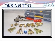
Directional exhausting can be ac<strong>com</strong>plished by<br />
installing Exhaust Kit, P/N 131456800, available<br />
through your parts distributor. Follow the instructions<br />
supplied with the kit.<br />
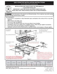
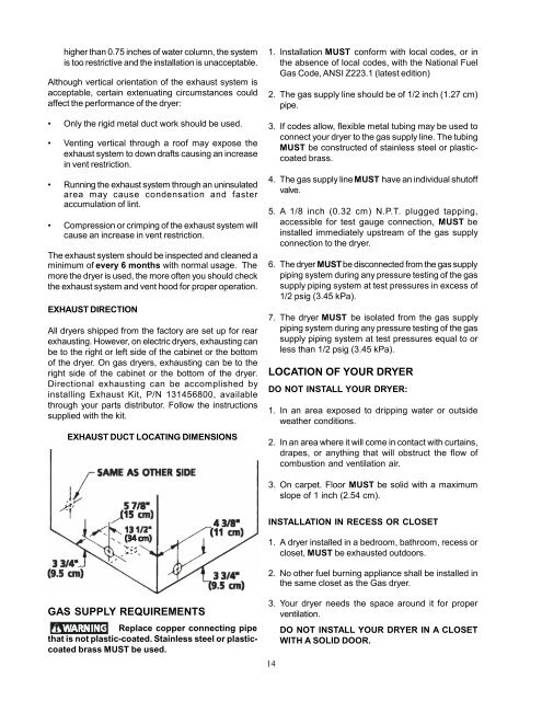
EXHAUST DUCT LOCATING DIMENSIONS<br />
1. Installation MUST conform with local codes, or in<br />
the absence of local codes, with the National Fuel<br />
Gas Code, ANSI Z223.1 (latest edition)<br />
2. The gas supply line should be of 1/2 inch (1.27 cm)<br />
pipe.<br />
3. If codes allow, flexible metal tubing may be used to<br />
connect your dryer to the gas supply line. The tubing<br />
MUST be constructed of stainless steel or plasticcoated<br />
brass.<br />
4. The gas supply line MUST have an individual shutoff<br />
valve.<br />
5. A 1/8 inch (0.32 cm) N.P.T. plugged tapping,<br />
accessible for test gauge connection, MUST be<br />
installed immediately upstream of the gas supply<br />
connection to the dryer.<br />
6. The dryer MUSTbe disconnected from the gas supply<br />
piping system during any pressure testing of the gas<br />
supply piping system at test pressures in excess of<br />
1/2 psig (3.45 kPa).<br />
7. The dryer MUST be isolated from the gas supply<br />
piping system during any pressure testing of the gas<br />
supply piping system at test pressures equal to or<br />
less than 1/2 psig (3.45 kPa).<br />
LOCATION OF YOUR DRYER<br />
DO NOT INSTALL YOUR DRYER:<br />
1. In an area exposed to dripping water or outside<br />
weather conditions.<br />
2. In an area where it will <strong>com</strong>e in contact with curtains,<br />
drapes, or anything that will obstruct the flow of<br />
<strong>com</strong>bustion <strong>and</strong> ventilation air.<br />
3. On carpet. Floor MUST be solid with a maximum<br />
slope of 1 inch (2.54 cm).<br />
INSTALLATION IN RECESS OR CLOSET<br />
1. A dryer installed in a bedroom, bathroom, recess or<br />
closet, MUST be exhausted outdoors.<br />
2. No other fuel burning appliance shall be installed in<br />
the same closet as the Gas dryer.<br />
GAS SUPPLY REQUIREMENTS<br />
Replace copper connecting pipe<br />
that is not plastic-coated. Stainless steel or plasticcoated<br />
brass MUST be used.<br />
3. Your dryer needs the space around it for proper<br />
ventilation.<br />
14<br />
DO NOT INSTALL YOUR DRYER IN A CLOSET<br />
WITH A SOLID DOOR.