C:\Documents and Settings\Allen - MSAWorld.com
C:\Documents and Settings\Allen - MSAWorld.com
C:\Documents and Settings\Allen - MSAWorld.com

You also want an ePaper? Increase the reach of your titles
YUMPU automatically turns print PDFs into web optimized ePapers that Google loves.
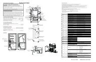
The drive cam arm, switch cam arm <strong>and</strong> the switches<br />
arm <strong>and</strong><br />
SWITCH CAM<br />
ARM<br />
When the dryer is connected to power, power is applied<br />
to the input terminals of switches A <strong>and</strong> B of the timer.<br />
The switches contacts which are spring-loaded closed,<br />
are opened by pushing down on the switches arm. Switch<br />
Acontrols power to the timer motor, indicator light, thermal<br />
limiter, start switch, dryer motor <strong>and</strong> door switch. Switch<br />
B controls power to the fabric selector switch, control<br />
thermostat, safety thermostat <strong>and</strong> the heater source<br />
circuit.<br />
The switches are controlled by the switch control cam.<br />
When the point of the tooth of the switch cam is engaged<br />
with the extrusion of the cam switch arm, the cam switch<br />
arm pushes down on the switches arm, <strong>and</strong> opens<br />
switches A <strong>and</strong> B.<br />
DRIVE CAM<br />
ARM<br />
SWITCHES ARM<br />
switches A <strong>and</strong> B.<br />
Note:<br />
Picture shown with drive cam removed.<br />
When the coin chute is pushed in, the extension on the<br />
coin chute depresses the arm of the spring loaded timer<br />
escape mechanism. When the coin chute is released<br />
the arm of the escape mechanism moves forward <strong>and</strong><br />
advances the switch cam one increment.<br />
29