C:\Documents and Settings\Allen - MSAWorld.com
C:\Documents and Settings\Allen - MSAWorld.com
C:\Documents and Settings\Allen - MSAWorld.com

You also want an ePaper? Increase the reach of your titles
YUMPU automatically turns print PDFs into web optimized ePapers that Google loves.
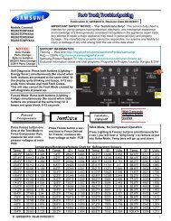
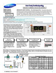
selector switch is set to the low heat position, the lower<br />
set of contacts of the fabric selector switch are closed.<br />
This applies line to line voltage to the heater in the control<br />
thermostat. Without the resistor in the circuit, the current<br />
flowing through the heater is higher producing more heat.<br />
The control thermostat now cycles on the heat in the<br />
blower housing <strong>and</strong> the increased heat of the control<br />
thermostat heater. This lowers the operating temperature<br />
in the dryer drum.<br />
The Heating Circuit:<br />
Switch B applies line 1 power throgh the contacts of the<br />
control thermostat to the normally close contacts of the<br />
safety thermostat that is mounted on theheating element<br />
assembly.<br />
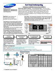
The safety thermostat is a safety device that prevents<br />
the dryer from overheating if the contacts of the control<br />
thermostat fail closed. The contacts of the safety<br />
thermostat, normally closed, are set to open at a<br />
temperature above the upper limits of the control<br />
thermostat. From the output terminal of the safety<br />
thermostat, line 1 is connected to one side of the element.<br />
The other side of the heating element is connected to<br />
line 2 through the contacts of the second centrifugal<br />
switch in the drive motor. This switch prevents power<br />
from being applied to the element if the motor is not<br />
running.<br />
Drying Time:<br />
The amount of drying time is determined by the timing<br />
cam of the accumulator (timer) <strong>and</strong> can be varied from<br />
180 minutes to 15 minutes by replacing the timing cam.<br />
Electrical Operation (Gas Dryers Models)<br />
Note: Always refer to the wiring diagram or schematic<br />
with the product.<br />
When the dryer is connected to electrical power, line 1<br />
is connected to switches A <strong>and</strong> B of the accumulator<br />
(timer). Neutral is connected to the timer motor <strong>and</strong> the<br />
door switch.<br />
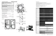
SAMPLE WIRING DIAGRAM<br />
L1<br />
120 VAC<br />
N<br />
GRN<br />
GRN<br />
BLUE<br />
CABINET<br />
TOP PANEL<br />
ACCUMULATOR<br />
TM<br />
RED<br />
A<br />
RED<br />
BLUE<br />
WHT<br />
WHT<br />
DOOR SWITCH<br />
BLUE C NO<br />
INDICATOR LIGHT<br />
TAN<br />
WHT<br />
GRAY<br />
START<br />
SWITCH<br />
4<br />
GRAY<br />
6 2<br />
START<br />
GRN<br />
YELLOW<br />
TAN<br />
RUN<br />
MOTOR 5 1<br />
CABINET BASE<br />
YEL<br />
B<br />
FABRIC SELECTOR<br />
SWITCH<br />
ORG<br />
4 5<br />
2.4K <br />
BLUE<br />
CONTROL<br />
THERMOSTAT<br />
37<br />
7K <br />
PINK<br />
PINK<br />
ORG<br />
SAFETY<br />
THERMOSTAT<br />
ORG<br />
SENSOR<br />
WHT WHT<br />
SEC<br />
COIL<br />
HOLDING<br />
COIL<br />
IGNITER<br />
WHT<br />
WHT<br />
BOOSTER<br />
COIL