C:\Documents and Settings\Allen - MSAWorld.com
C:\Documents and Settings\Allen - MSAWorld.com
C:\Documents and Settings\Allen - MSAWorld.com

Create successful ePaper yourself
Turn your PDF publications into a flip-book with our unique Google optimized e-Paper software.
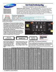
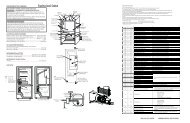
safety thermostat, line 1 is connected to one side of the<br />
holding coil of the gas valve, the secondary coil of the<br />
gas valve <strong>and</strong> the sensor mounted on the burner chamber.<br />
The holding coil, secondary coil, booster coil, sensor<br />
<strong>and</strong> igniter circuits interact with one another to assure<br />
safe operation of the dryer gas burner.<br />
Igniter<br />
Booster<br />
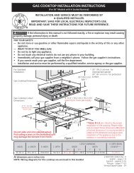
The gas valve has two chambers in series; both must be<br />
opened before gas will flow into the burner. The solenoid<br />
that controls the gas flow through the first chamber has<br />
two coils: the booster coil <strong>and</strong> the holding coil. The<br />
solenoid that controls the second chamber has one coil,<br />
the secondary coil.<br />
N<br />
Secondary<br />
Holding<br />
It is necessary to raise the temperature above 1100° F<br />
to ignite gas. As current flows through the igniter, the<br />
temperature of igniter raises from room temperature to<br />
approximately 1800° F within 30 seconds. The contacts<br />
of the sensor are heat sensitive <strong>and</strong> set to open above<br />
the ignition temperature of gas. When the sensor<br />
contacts open, current flows through the secondary coil<br />
opening the second chamber <strong>and</strong> allowing gas to the<br />
burner which is then ignited by the heat of the igniter.<br />
When the contacts of the sensor are open, the parallel<br />
circuit formed by the igniter <strong>and</strong> the booster coil are in<br />
series with the secondary coil which lowers the current<br />
flow through the igniter <strong>and</strong> booster coil. Since it takes<br />
less magnetic force to hold a solenoid open than it does<br />
to open it, the first solenoid remains open when the<br />
current through the booster coil is reduced. The reduction<br />
of current flow through the igniter reduces heat from the<br />
igniter but the sensor contacts are held open by the<br />
heat of the burner flame.<br />
Drying Time:<br />
The other side of the holding coil, booster coil <strong>and</strong> igniter<br />
are connected to neutral through the centrifugal switches<br />
in the motor (closed when the motor is running). When<br />
power is applied across these circuits, current flows<br />
through the holding coil, but the holding coil does not<br />
have enough magnetic force to open the solenoid by<br />
itself. At the same time, current flows through sensor<br />
contacts providing power to the booster coil <strong>and</strong> the<br />
igniter. When current flows through both the holding <strong>and</strong><br />
booster coils, the first chamber opens. The contacts of<br />
the sensor are in parallel with the secondary coil. As<br />
long as the contacts of the sensor remain closed, current<br />
flow bypasses the secondary coil <strong>and</strong> gas is prevented<br />
from flowing through the second chamber of the valve to<br />
the burner.<br />
L1<br />
The amount of drying time is determined by the timing<br />
cam of the accumulator (timer), <strong>and</strong> can be varied from<br />
180 minutes to 15 minutes by replacing the timing cam.<br />
.<br />
39