C:\Documents and Settings\Allen - MSAWorld.com
C:\Documents and Settings\Allen - MSAWorld.com
C:\Documents and Settings\Allen - MSAWorld.com

You also want an ePaper? Increase the reach of your titles
YUMPU automatically turns print PDFs into web optimized ePapers that Google loves.
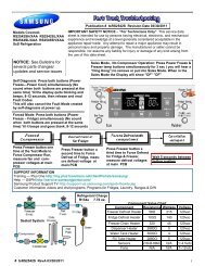
Air leaks:<br />
Two types of air leaks may occur:<br />
1. Air being drawn in around the door opening, between<br />
the drum <strong>and</strong> the front panel, or around the foam seal<br />
between the front duct <strong>and</strong> the blower housing,<br />
replaceing some of the air being drawn through the<br />
drum <strong>and</strong> lowers the efficiencyof the dryer.<br />
Note:<br />
With short direct vent runs; such as you have<br />
when the dryer is installed against an outside<br />
wall, use a 2 1/2” vent cap rather than a 4” vent<br />
cap.<br />
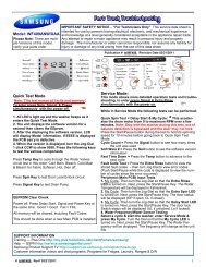
Electrical Operation (Electric Dryers Models)<br />
Note: Always refer to the wiring diagram or schematic<br />
with the product.<br />
Note:<br />
An air leak that occurs around the door opening<br />
or between the drum <strong>and</strong> the front panel usually<br />
will cause lint to build up on the inner panel of<br />
the door.<br />
When the dryer is connected to electrical power, line 1<br />
is connected to switches A <strong>and</strong> B of the accumulator<br />
(timer). Line 2 is connected to the second centrifugal<br />
switch of the drive motor.<br />
2. Air being pushed out around the blower housing or<br />
vent pipe inside the dryer, allows some of the moisture<br />
that has been removed from the clothes to be<br />
recirculated.<br />
Short unrestricted vents:<br />
The venting system in the dryer is designed to operate<br />
under some back pressure. This back pressure is<br />
needed to slow the airflow <strong>and</strong> allow the air to be heated<br />
before it passes through the clothes.<br />
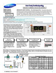
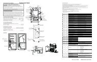
Accumulator (Timer)Circuits:<br />
Line 1 is applied to switches A <strong>and</strong> B of the accumulator.<br />
When a coin slide is pushed in <strong>and</strong> released, the<br />
accumulator closes the contacts of switches A <strong>and</strong> B.<br />
The contacts of switch A remain closed for the <strong>com</strong>plete<br />
cycle. The contacts of switch B open about five minutes<br />
before the end of the cycle to allow the dryer to cool<br />
down. With the contacts of switch A closed, power is<br />
applied to the timer motor, thermal limiter, indicator light<br />
<strong>and</strong> drive motor. Since the other wire to the timer motor<br />
L1<br />
SAMPLE WIRING DIAGRAM<br />
240 VAC<br />
120 VAC 120 VAC<br />
L2<br />
RED<br />
ACCUMULATOR<br />
TM<br />
BLUE<br />
BLUE<br />
CABINET<br />
BLUE<br />
N GRN<br />
WIRE NOT INCLUDED IN MODELS PROVIDED<br />
WITH 4 - WIRE POWER CORD.<br />
C NO<br />
DOOR SWITCH<br />
GRAY<br />
BLK<br />
6<br />
2<br />
RED<br />
A<br />
WHT<br />
WHT<br />
WHT<br />
THERMAL<br />
LIMITER<br />
WHT<br />
4<br />
START<br />
RUN<br />
MOTOR 5<br />
GRAY<br />
1<br />
GRN<br />
FABRIC SELECTOR<br />
SWITCH<br />
INDICATOR LIGHT<br />
YEL<br />
TAN<br />
TAN<br />
START SWITCH<br />
CABINET<br />
BASE<br />
YEL<br />
HEATER<br />
4500 WATTS<br />
B<br />
3 K 4 5 BLUE<br />
28K <br />
ORG/BLK<br />
BLK<br />
ORG<br />
CONTROL<br />
THERMOSTAT<br />
ORG/BLK<br />
SAFETY<br />
THERMOSTAT<br />
GRN<br />
GRN<br />
CABINET<br />
COIN BOX<br />
CABINET<br />
TOP PANEL<br />
35