Shanks Owners Manual (04 Build) 35, 35H & 40 (PDF) - EP Barrus
Shanks Owners Manual (04 Build) 35, 35H & 40 (PDF) - EP Barrus
Shanks Owners Manual (04 Build) 35, 35H & 40 (PDF) - EP Barrus

Create successful ePaper yourself
Turn your PDF publications into a flip-book with our unique Google optimized e-Paper software.
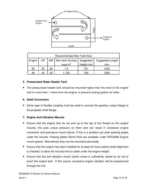
Air Bleed Points<br />
Coolant from<br />
Engine<br />
Height<br />
Coolant to<br />
Engine<br />
Length<br />
Recommended Skin Tank Size<br />
Engine HP KW Skin tank Surface<br />
area m 2<br />
Suggested<br />
Height mm<br />
Suggested Length<br />
mm<br />
<strong>35</strong> <strong>35</strong> 26 1.0 721 1442<br />
<strong>40</strong> <strong>40</strong> 30 1.125 750 1500<br />
5. Pressurised Water Header Tank<br />
• The pressurised header tank should be mounted higher than the level of the engine<br />
and no more than 1 metre from the engine, to prevent cooling system air locks.<br />
6. Shaft Connection<br />
• Some type of flexible coupling must be used to connect the gearbox output flange to<br />
the propeller shaft flange.<br />
7. Engine Anti-Vibration Mounts<br />
• Ensure that the engine feet do not end up at the top of the thread on the engine<br />
mounts, this puts undue pressure on them and can result in excessive engine<br />
movement and premature mount failure. If this is a problem put steel packing plates<br />
under the mounts. Packing plates 25mm thick are available: order RDG3906 Engine<br />
mount spacer. Alternatively they can be manufactured locally.<br />
• Ensure that the engine has been installed for at least 24 hours before shaft alignment<br />
is checked, to allow the mounts time to settle under the engine weight.<br />
• Ensure that the anti-vibration mount centre screw is sufficiently raised so as not to<br />
touch the engine bed. If this occurs, excessive engine vibration will be experienced<br />
through the hull.<br />
RDG6038170 <strong>Shanks</strong> <strong>04</strong> <strong>Owners</strong> <strong>Manual</strong><br />
Issue 4 Page 10 of 45