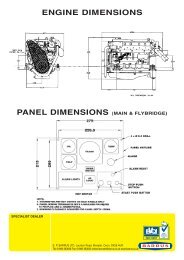
Shanks Owners Manual (04 Build) 35, 35H & 40 (PDF) - EP Barrus
Shanks Owners Manual (04 Build) 35, 35H & 40 (PDF) - EP Barrus
Shanks Owners Manual (04 Build) 35, 35H & 40 (PDF) - EP Barrus

Create successful ePaper yourself
Turn your PDF publications into a flip-book with our unique Google optimized e-Paper software.
9. Engine Alignment<br />
• The gearbox output shaft flange and propeller shaft input flange must be almost<br />
perfectly aligned. A maximum of ± 0.05mm (0.002") misalignment in any plane is<br />
acceptable. Ensure alignment is rechecked after the first 4 hours of running, after the<br />
first month, and thereafter annually.<br />
• If the engine is out of alignment it will result in excessive vibration and possible<br />
damage to the stern tube and propeller shaft.<br />
• Boats that are fitted with fully flexible drive couplings should still have the engine and<br />
shaft alignment as close as possible. A dummy shaft may be required for this<br />
purpose. (Note: some types of flexible shaft couplings require the input and output to<br />
be misaligned, check with the coupling manufacturer’s installation instructions).<br />
10. Electrics<br />
WARNING:<br />
DO NOT RUN THE ENGINE WITHOUT THE BLUE WIRE IN PLACE IF THE DOMESTIC<br />
BATTERIES ARE NOT CONNECTED OR ALTERNATOR DAMAGE WILL OCCUR.<br />
• Do not attach any part, hose or cable to the engine wiring harness. There is a<br />
warning label attached to the harness to remind you of this.<br />
• Connect the wiring extension harness multi plug to the panel plug, and the other end<br />
to the engine. Connect the single wire that is adjacent to the 11 pin plug<br />
• Connect the start battery positive cable to the engine starter motor solenoid terminal.<br />
• The starter motor battery cable must have a cross sectional area of at least 50mm 2 .<br />
• For twin alternator engines, connect the domestic battery positive cable to the 110A<br />
alternator B+ terminal (see wiring diagram). This ensures that the <strong>40</strong>A alternator<br />
charges the start battery and the 110A (or 160A) alternator charges the domestic<br />
battery, removing the requirement for a split charging system or relay.<br />
• The blue link wire between the 110A Alternator B+ terminal or 160A “pos out” terminal<br />
and the starter motor solenoid must be removed when the domestic battery positive<br />
lead is connected to the terminal post.<br />
• A cable will need to be manufactured locally and fitted between the lower 110A or<br />
160A alternator B+/ “pos out” terminal and domestic battery positive terminal. Cable<br />
should have a minimum cross sectional area of <strong>35</strong>mm 2 (175 A)<br />
RDG6038170 <strong>Shanks</strong> <strong>04</strong> <strong>Owners</strong> <strong>Manual</strong><br />
Issue 4 Page 13 of 45