Light Truck Frame Joint Stiffness Study Phase 1 Final Report
Light Truck Frame Joint Stiffness Study Phase 1 Final Report
Light Truck Frame Joint Stiffness Study Phase 1 Final Report

You also want an ePaper? Increase the reach of your titles
YUMPU automatically turns print PDFs into web optimized ePapers that Google loves.
FINITE ELEMENT ANALYSIS<br />
Defining the <strong>Joint</strong>s<br />
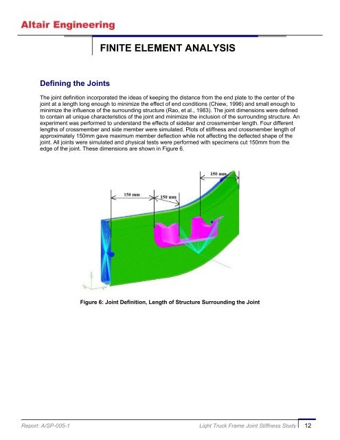
The joint definition incorporated the ideas of keeping the distance from the end plate to the center of the<br />
joint at a length long enough to minimize the effect of end conditions (Chiew, 1996) and small enough to<br />
minimize the influence of the surrounding structure (Rao, et al., 1983). The joint dimensions were defined<br />
to contain all unique characteristics of the joint and minimize the inclusion of the surrounding structure. An<br />
experiment was performed to understand the effects of sidebar and crossmember length. Four different<br />
lengths of crossmember and side member were simulated. Plots of stiffness and crossmember length of<br />
approximately 150mm gave maximum member deflection while not affecting the deflected shape of the<br />
joint. All joints were simulated and physical tests were performed with specimens cut 150mm from the<br />
edge of the joint. These dimensions are shown in Figure 6.<br />
Figure 6: <strong>Joint</strong> Definition, Length of Structure Surrounding the <strong>Joint</strong><br />
<strong>Report</strong>: A/SP-005-1 <strong>Light</strong> <strong>Truck</strong> <strong>Frame</strong> <strong>Joint</strong> <strong>Stiffness</strong> <strong>Study</strong> 12