Light Truck Frame Joint Stiffness Study Phase 1 Final Report
Light Truck Frame Joint Stiffness Study Phase 1 Final Report
Light Truck Frame Joint Stiffness Study Phase 1 Final Report

Create successful ePaper yourself
Turn your PDF publications into a flip-book with our unique Google optimized e-Paper software.
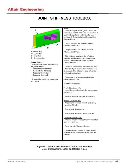
JOINT STIFFNESS TOOLBOX<br />
Notes:<br />
* Modify the input values (yellow) based on<br />
your design criteria. There are two columns in<br />
which in to input and evaluate data, case 1<br />
and case 2. The calculated stiffness will be<br />
displayed in red.<br />
* Design variables are listed in order of<br />
influence on stiffness.<br />
Illustration Key:<br />
A = Outer Rail<br />
B = Inner Rail<br />
C = Crossmember<br />
Design Rules:<br />
* These are the major contributors to<br />
the joint stiffness:<br />
- Crossmember thickness<br />
- Inner side rail thickness<br />
- Crossmember height<br />
- Crossmember width<br />
* The weld flange should be as small<br />
as possible.<br />
* Design variables are listed in order of<br />
influence on stiffness.<br />
* Click on the animation to the left of the<br />
variables and loading conditions to see an<br />
animation of respective shape variable or<br />
loading condition.<br />
* The mass calculation is based on 150 mm<br />
extension of joint members from the side rail<br />
to interface. This is to serve as a reference,<br />
not the absolute value.<br />
* The password to unprotect cells in this<br />
spreadsheet is: steel.<br />
<strong>Joint</strong> Observations:<br />
Fore/Aft Loadcase (Mz)<br />
* Lots of flange deflection in the crossmember<br />
and siderail.<br />
* Side rail wall also has a lot of deflection.<br />
Vertical Loadcase (Mx)<br />
* Crossmember flange deflects quite a bit,<br />
especially at the top.<br />
* Side rail wall deflects a lot.<br />
* Side rail wall also has a lot of deflection.<br />
Torsional Loadcase (My)<br />
* Weak in torsion because the crossmember<br />
is an open section.<br />
* There is a lot of flange deflection.<br />
* The top flanges do not attach to anythingattaching<br />
to the side rail would increase the<br />
stiffness.<br />
Figure 41: <strong>Joint</strong> 5 <strong>Joint</strong> <strong>Stiffness</strong> Toolbox Spreadsheet<br />
<strong>Joint</strong> Observations, Notes and Design Rules<br />
<strong>Report</strong>: A/SP-005-1 <strong>Light</strong> <strong>Truck</strong> <strong>Frame</strong> <strong>Joint</strong> <strong>Stiffness</strong> <strong>Study</strong> 68