Gladiator Admittance Manual - Hawk Measurement
Gladiator Admittance Manual - Hawk Measurement
Gladiator Admittance Manual - Hawk Measurement
Create successful ePaper yourself
Turn your PDF publications into a flip-book with our unique Google optimized e-Paper software.
INSTRUCTION MANUAL<br />
<strong>Admittance</strong> Smart Switch Series<br />
- An all-round point level switch -<br />
A higher level of performance
<strong>Admittance</strong> Smart Switch Series<br />
<strong>Manual</strong><br />
Rev 1.3, Feb 2009<br />
INTRODUCTION<br />
CONTENTS<br />
PROPRIETARY NOTICE<br />
The information contained in this publication<br />
is derived in part from proprietary and patent<br />
data. This information has been prepared for<br />
the express purpose of assisting operating and<br />
maintenance personnel in the efficient use of<br />
the instrument described herein. Publication of<br />
this information does not convey any rights to<br />
use or reproduce it, or to use for any purpose<br />
other than in connection with the installation,<br />
operation and maintenance of the equipment<br />
described herein.<br />
WARNING<br />
This instrument contains electronic components<br />
that are susceptible to damage by static<br />
electricity. Proper handling procedures must<br />
be observed during the removal, installation, or<br />
handling of internal circuit boards or devices:<br />
Handling Procedure:<br />
1. Power to unit must be removed prior to<br />
commencement of any work.<br />
2. Personnel must be grounded, via wrist strap<br />
or other safe, suitable means, before any<br />
printed circuit board or other internal devices<br />
are installed, removed or adjusted.<br />
3. Printed circuit boards must be transported<br />
in a conductive bag or other conductive<br />
container. Boards must not be removed from<br />
protective container until the immediate time<br />
of installation. Removed boards must be<br />
placed immediately in a protective container<br />
for transport, storage, or return to factory.<br />
Comments:<br />
This instrument is not unique in its content<br />
of ESD (electrostatic discharge) sensitive<br />
components. Most modern electronic designs<br />
contain components that utilize metal oxide<br />
technology (NMOS, CMOS, etc.). Experience<br />
has proven that even small amounts of static<br />
electricity can damage or destroy these<br />
devices. Damaged components, even though<br />
they appear to function properly, exhibit early<br />
failure.<br />
<br />
General Description<br />
Features 2<br />
Typical Applications 3<br />
Dimensions 5<br />
Mounting 9<br />
Flexile Cable Probe Adjustment 11<br />
Wiring<br />
- Smart Probe 2<br />
- Remote Probe 3<br />
- Relay Functions 4<br />
- Multidrop Connections 15<br />
- <strong>Hawk</strong>Link GSM 6<br />
- Test Terminal 8<br />
Smart Probe Setup Procedure 19<br />
Remote Setup Procedure 22<br />
Remote Software Menu 24<br />
- Software Tree 25<br />
- QuickSet 26<br />
- Advanced Menu 27<br />
- Diagnostic Displays 30<br />
Multidrop Communication 32<br />
Remote Communication 33<br />
Troubleshooting 34<br />
Part Numbering 35<br />
Specifications 37<br />
Dielectric Constant 38<br />
CE Declaration 39<br />
Contact Information (back cover)<br />
Sultan 234 Series
<strong>Admittance</strong> Smart Switch Series<br />
<strong>Manual</strong><br />
Rev 1.3, Feb 2009<br />
GENERAL DESCRIPTION<br />
FEATURES<br />
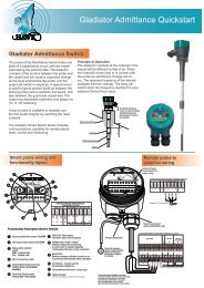
The <strong>Gladiator</strong> Smart <strong>Admittance</strong> Switch<br />
is a third generation, state-of-the-art<br />
level probe, designed to operate in<br />
tough industrial environments. The<br />
probe of the <strong>Admittance</strong> Switch forms<br />
one plate of a capacitance circuit, with<br />
the vessel wall making the second plate.<br />
The dielectric constant of the product<br />
between the probe and the vessel wall<br />
will cause a capacitive change as the<br />
level approaches the probe, and the<br />
output will switch in response. A special<br />
circuit is used to ignore product build-up<br />
between the sensing probe (active element)<br />
and guard, and also between the<br />
guard and vessel wall. The output has<br />
adjustable hysteresis and delays for ‘on’<br />
or ‘off’ switching.<br />
A test function is available to remotely<br />
confirm the probe integrity by switching<br />
the relay contacts.<br />
The <strong>Gladiator</strong> Smart Switch Series<br />
includes communications flatten roof capability for<br />
remote adjustment, control and monitoring.<br />
•<br />
•<br />
•<br />
•<br />
•<br />
•<br />
•<br />
•<br />
•<br />
•<br />
•<br />
•<br />
•<br />
Excellent immunity to product build-up<br />
Excellent temperature stability - no<br />
false trips<br />
Simple ‘1-minute’ set-up<br />
Relay outputs: Smart probe (1)<br />
Remote (2)<br />
Remote test function<br />
Adjustable ON and OFF delays (0-20 sec)<br />
Smart communication options:<br />
Gos<strong>Hawk</strong>, Modbus, HART, Profibus<br />
DP, DeviceNet<br />
Remote GSM Connection option<br />
Remote amplifier to probe separation<br />
up to 500 m (1640 ft)<br />
Bright visual status indication on<br />
Probe<br />
LCD Diagnostic for Remote version<br />
Independant housing alignment after<br />
mounting thread locked<br />
Non contact switching possible with<br />
many materials<br />
Principle of Operation<br />
The dielectric constant of the material<br />
in the vessel will be different to that of<br />
air. When the material comes near or in<br />
contact with the probe an admittance<br />
change will occur. The resonant frequency<br />
of the internal oscillator will then<br />
change. The relay will switch when the<br />
frequency reaches the user selected<br />
Switch Point value.<br />
Material build up<br />
Guard<br />
Probe Insulation<br />
> 100mm<br />
Ground the housing to<br />
vessel, if vessel is metallic.<br />
Ground the housing to<br />
plant ground, if vessel is<br />
non-metallic.<br />
Probe
<strong>Admittance</strong> Smart Switch Series<br />
<strong>Manual</strong><br />
Rev 1.3, Feb 2009<br />
TYPICAL APPLICATIONS<br />
High level switch in plastic pellet silo<br />
High level switch in grain application<br />
Cyclone bin level switch<br />
<br />
Sultan 234 Series
<strong>Admittance</strong> Smart Switch Series<br />
<strong>Manual</strong><br />
Rev 1.3, Feb 2009<br />
TYPICAL APPLICATIONS<br />
Continuous filling with build-up<br />
on probe<br />
High and low level switch in a hopper<br />
High level<br />
(top mounted)<br />
Low level<br />
(top mounted)<br />
Probe<br />
If impact from falling material is<br />
expected, mount a protection plate<br />
above the probe to ensure no<br />
physical damage can occur to the<br />
probe in normal operation. If it is not<br />
possible to do this or to move the<br />
probe to an alternative position, use<br />
a microwave switch.<br />
Low level<br />
(side mounted)<br />
See www.hawkmeasure.com for<br />
further information on Microwave<br />
switches and other level products.
10mm (0.4<br />
<strong>Admittance</strong> Smart Switch Series<br />
<strong>Manual</strong><br />
Rev 1.3, Feb 2009<br />
DIMENSIONS<br />
REMOTE AMPLIFIER ENCLOSURE<br />
192mm (7.6”)<br />
106mm (4.2”)<br />
76.5 (3”)<br />
DIN Rail Mounting<br />
(clips included)<br />
Front Side Back<br />
192mm (7.6”)<br />
145mm (5.7”)<br />
10.5mm (0.4”)<br />
160mm (6.3”)<br />
106mm (4.2”)<br />
160mm (6.3”)<br />
142mm (5.6”)<br />
38mm (1.5”)<br />
83mm (3.3”)<br />
3 x 20mm (0.7”), 1x16mm (0.6”)<br />
Knock outs<br />
166mm (6.5”)<br />
61mm (2.4”) 8mm (0.3”)<br />
151mm (5.9”)<br />
166mm (6.5”)<br />
10mm (0.4”)<br />
OPTIONAL FLANGE<br />
HIGH TEMPERATURE<br />
EXTENSIONS (
<strong>Admittance</strong> Smart Switch Series<br />
<strong>Manual</strong><br />
Rev 1.3, Feb 2009<br />
DIMENSIONS<br />
REMOTE PROBE<br />
SMART PROBE<br />
Window for<br />
viewing status<br />
LEDs<br />
85mm (3.3”)<br />
Window for<br />
viewing status<br />
LEDs<br />
85mm (3.3”)<br />
M20 cable gland<br />
or 3/4” NPT adaptor<br />
50mm (2”)<br />
90mm (3.5”)<br />
2 x M20<br />
cable glands<br />
or 3/4” NPT adaptors<br />
50mm (2”)<br />
90mm (3.5”)<br />
Ground 100mm (3.9”)<br />
Mounting<br />
thread<br />
Ground 100mm (3.9”)<br />
Optional Flange<br />
Active (mm)<br />
Guard 150mm (5.9”)<br />
probe length<br />
Active (mm)<br />
Guard 150mm (5.9”)<br />
probe length<br />
16mm (0.6”)<br />
16mm (0.6”)<br />
Probe Length (mm, inch) Active + Guard + Ground<br />
P30 (300mm,11.8”)<br />
P50 (500mm, 19.7”)<br />
P100 (1000mm, 39.4”)<br />
= 50mm, 2”<br />
= 250mm, 9.8”<br />
= 750mm, 29.5”<br />
+<br />
+<br />
+<br />
250mm, 9.8”<br />
250mm, 9.8”<br />
250mm, 9.8”
<strong>Admittance</strong> Smart Switch Series<br />
<strong>Manual</strong><br />
Rev 1.3, Feb 2009<br />
DIMENSIONS<br />
FLEXIBLE CABLE PROBE<br />
M20 x 1.5<br />
or 3/4” NPT adaptor<br />
115mm<br />
Mounting Thread<br />
(1.5” NPT or BSP only)<br />
100mm (3.9”)<br />
Ground<br />
SS 316<br />
Teflon<br />
150mm (5.9”)<br />
Guard<br />
SS 316<br />
215mm (8.4”)<br />
Teflon<br />
83mm (3.3”)<br />
Cable Length<br />
Ø 8mm (0.3”)<br />
SS 316<br />
Rope<br />
Active<br />
83mm (3.3”)<br />
Removable grub screws<br />
for cable adjustment<br />
SS 316<br />
250mm (9.8”)<br />
Weight<br />
Ø 40mm (1.6”)<br />
Cable Length (mm, inch) Active + Guard + Ground (Rope Length)<br />
C100 (1000mm, 39.3”) = 750mm, 29.5” + 250mm, 9.8” 451mm, 17.8”<br />
C200 (2000mm, 78.7”) = 1750mm, 68.9” + 250mm, 9.8” 1451mm, 57.1”<br />
C300 (3000mm, 118.1”) = 2750mm, 108.3” + 250mm, 9.8” 2451mm, 96.5”<br />
<br />
Sultan 234 Series
<strong>Admittance</strong> Smart Switch Series<br />
<strong>Manual</strong><br />
Rev 1.3, Feb 2009<br />
DIMENSIONS<br />
HIGH TEMPERATURE PROBES<br />
HIGH TEMP PROBE (
<strong>Admittance</strong> Smart Switch Series<br />
<strong>Manual</strong><br />
Rev 1.3, Feb 2009<br />
MOUNTING<br />
Probes can be mounted from the top,<br />
side and bottom.<br />
Points to consider when mounting:<br />
A. Material Infeed Clearance<br />
Install the probe away from the infeed to<br />
minimize the influence of build-up and<br />
impact forces, and to avoid false triggering<br />
from product flow.<br />
B. Wall Clearance<br />
Install the probe far enough away from<br />
the wall to prevent the probe or cable<br />
from coming into contact with the vessel<br />
wall. Avoid creating a confined area<br />
where material could build-up over time.<br />
See note <br />
C. Nozzle Clearance<br />
Where possible, ensure the probe guard<br />
has at least 100mm clearance from the<br />
nozzle.<br />
Correct Mounting in a Nozzle<br />
Recommended 50mm (2”)<br />
min. 100mm (4”)<br />
D. Top mounting<br />
When top mounting, ensure adequate<br />
clearance is provided between probe<br />
and wall. Avoid creating a confined area<br />
where material could build-up over time.<br />
In the case of cable probe versions,<br />
ensure enough clearance is provided<br />
between the probe and wall to allow for<br />
build-up of material occurring on the<br />
wall.<br />
See note <br />
E. Side mounting<br />
It is highly recommended to install any<br />
side mounted probe at a downward<br />
angle of 30-45º. Use a protection plate<br />
for side mounting where the probe may<br />
be subject to impact strain or collapsing<br />
material.<br />
F. Bottom mounting<br />
Bottom mounting is not recommended.<br />
Only mount from the bottom if no buildup<br />
of material occurs. If low level mounting<br />
is required, suitable options are<br />
shown in the diagram on page 10.<br />
CORRECT MOUNTING NOTES:<br />
(Refer to picture on page 10)<br />
Select correct probe for high temperature<br />
applications.<br />
Allow adequate air flow for cooling extensions<br />
dissipate heat.<br />
INCORRECT MOUNTING NOTES:<br />
Incorrect mounting because the<br />
probe is too close to the wall or roof.<br />
Positioning too close to a wall or roof<br />
will limit probe sensitivity. Material may<br />
build-up between the probe and the<br />
vessel.<br />
Incorrect mounting because the<br />
probe’s guard is mounted inside the<br />
nozzle. The correct arrangement is for<br />
the guard to protrude out of the mounting<br />
pipe at least 100mm. Product will buildup<br />
in the nozzle.<br />
<br />
Sultan 234 Series
<strong>Admittance</strong> Smart Switch Series<br />
<strong>Manual</strong><br />
Rev 1.3, Feb 2009<br />
MOUNTING<br />
Correct<br />
1<br />
2<br />
Incorrect<br />
If necessary mount a<br />
protection plate to<br />
prevent direct impact<br />
or to prevent pull<br />
from down feed.<br />
Possible product<br />
build-up<br />
Correct Correct<br />
Flexible cable<br />
1<br />
Correct<br />
Incorrect<br />
3<br />
Incorrect<br />
2<br />
Possible<br />
product<br />
build-up<br />
Correct<br />
30-45º<br />
Correct<br />
Housing can be rotated<br />
within 200º after the<br />
mounting thread is<br />
tightened, to allow cable<br />
entries to face downwards<br />
or allow optimal cable<br />
clearance.<br />
Correct<br />
Incorrect<br />
3<br />
Correct (non-preferred<br />
low level mounting)<br />
10
<strong>Admittance</strong> Smart Switch Series<br />
<strong>Manual</strong><br />
Rev 1.3, Feb 2009<br />
FLEXIBLE CABLE PROBE ADJUSTMENT<br />
Notes for adjusting probe rope length<br />
The <strong>Gladiator</strong> rope type probe can be<br />
altered to any sensing length between<br />
approx. 750mm and 3m by cutting down<br />
from the standard sizes as required.<br />
If a new rope is to be used, the rope<br />
should be cut to:<br />
Cable probe length - 549mm = new wire rope<br />
length (total sensing length - 549mm)<br />
For example, within a 1000mm (1m) cable:<br />
1000 = [rope + 549]<br />
So rope length = 451mm<br />
465mm (18.3”)<br />
Remove or install the probe weight grub<br />
screws with a 4mm allen key.<br />
When fastening the rope, apply threadlocking<br />
adhesive onto grub screws<br />
before re-installation.<br />
83mm<br />
83mm<br />
Concealed<br />
rope<br />
Concealed<br />
rope<br />
Rope<br />
Cable Probe Length<br />
Removable SS grub screws<br />
for cable adjustment<br />
250mm (9.8”)<br />
Weight<br />
11<br />
Sultan 234 Series
<strong>Admittance</strong> Smart Switch Series<br />
<strong>Manual</strong><br />
Rev 1.3, Feb 2009<br />
WIRING<br />
SMART PROBE<br />
Remove Plug-In<br />
terminal block for<br />
easier wiring.<br />
SENSITIVITY<br />
HI FSH CAL TEST<br />
DELAY<br />
1 2 3 4 5 6 7 8 9 10<br />
!<br />
The AC earth/ground<br />
cable must be connected<br />
to the ground screw<br />
inside the housing when<br />
using AC power.<br />
Hole for securing of<br />
optional identification tag<br />
If only one cable is used for both<br />
power and output signal, then the<br />
second entry port must be<br />
plugged or blinded. Every Smart<br />
unit is supplied with two M20<br />
glands (or 3/4”NPT adaptors)<br />
mounted on the unit and one<br />
blind plug loose.<br />
1. NC<br />
Ground the housing to<br />
vessel, if vessel is metallic.<br />
Ground the housing to<br />
plant ground, if vessel is<br />
non-metallic.<br />
RELAY<br />
2. COM<br />
M4 grounding screw<br />
GLADIATOR SMART PROBE TERMINAL LAYOUT<br />
3. NO<br />
4. Test<br />
COMMS DC-IN AC-IN<br />
A<br />
5.<br />
B<br />
6.<br />
<br />
7.<br />
8.<br />
N<br />
9.<br />
L1<br />
10.<br />
RS 485 12-30VDC 80-265 VAC<br />
-<br />
12
<strong>Admittance</strong> Smart Switch Series<br />
<strong>Manual</strong><br />
Rev 1.3, Feb 2009<br />
WIRING<br />
REMOTE PROBE TO AMPLIFER<br />
Remove Plug-In<br />
terminal block for<br />
easier wiring.<br />
GLADIATOR REMOTE PROBE TERMINAL LAYOUT<br />
TRANSDUCER<br />
1 2 3 4 5 6 7 8 9 10<br />
1. 2. 3. 4. 5. 6. 7. 8. 9. 10.<br />
WHITE<br />
BLUE<br />
RED<br />
BLACK<br />
Terminals 1, 2, 3, 4, 9, 10 not used.<br />
Hole for securing of<br />
optional identification tag<br />
GLADIATOR REMOTE AMPLIFIER TERMINAL LAYOUT<br />
M4 grounding screw<br />
NOT USED<br />
Test in<br />
RELAY 1<br />
NC<br />
COM<br />
NO<br />
RELAY 2<br />
(FAIL SAFE)<br />
NC<br />
COM<br />
NO<br />
Ground the housing to<br />
vessel, if vessel is metallic.<br />
Ground the housing to<br />
plant ground, if vessel is<br />
non-metallic.<br />
CURRENT<br />
SENSOR<br />
COMMS<br />
DC-IN<br />
AC-IN<br />
Is<br />
+ –<br />
RED<br />
BLACK<br />
BLUE<br />
WHITE<br />
NOT USED<br />
B<br />
A<br />
– +<br />
N<br />
L1<br />
24 VDC 80-265 VAC<br />
Cable type between Amplifier and Probe<br />
4 conductor shielded twisted pair instrument cable.<br />
Conductor size dependent on cable length.<br />
BELDEN 3084A, DEKORON or equivalent.<br />
Max: BELDEN 3084A = 500m (1640 ft)<br />
Max: DEKORON IED183AA002 = 350m (1150 ft)<br />
13<br />
Sultan 234 Series
<strong>Admittance</strong> Smart Switch Series<br />
<strong>Manual</strong><br />
Rev 1.3, Feb 2009<br />
WIRING<br />
RELAY FUNCTIONS<br />
Level Switch Contact Action<br />
FailSafe Low<br />
FSL<br />
Relay Action<br />
FailSafe High<br />
FSH (default)<br />
Relay - for Smart Probe Version<br />
(Set Relay Action selection switch<br />
pages 19 and 20)<br />
State 1<br />
1 2 3<br />
NC COM NO<br />
1 2 3<br />
NC COM NO<br />
Relay Status<br />
Smart Probe<br />
terminal numbers<br />
Remote Amplifier<br />
terminal function<br />
labels<br />
Relay 1 - for Remote Version<br />
(Set ‘Relay Action’ parameter<br />
pages 23 and 26)<br />
RISING LEVEL<br />
(not detected)<br />
LED Status<br />
*It is possible for the <strong>Gladiator</strong> to<br />
switch state before actual product<br />
contact with the probe. State 2 represents<br />
product being detected by<br />
the probe, even if it occurs without<br />
contact.<br />
State 2<br />
CONTACT LEVEL<br />
(detected)<br />
1 2 3<br />
NC COM NO<br />
1 2 3<br />
NC COM NO<br />
State 1<br />
1 2 3<br />
NC COM NO<br />
1 2 3<br />
NC COM NO<br />
FALLING LEVEL<br />
(not detected)<br />
POWER FAILURE<br />
1 2 3<br />
NC COM NO<br />
1 2 3<br />
NC COM NO<br />
FailSafe Switch Contact Action<br />
Relay 2 - Remote version only.<br />
For Smart Probes the Test terminal<br />
can act as a solid state output<br />
with a similar function.<br />
(see page 18)<br />
POWER FAILURE<br />
OR<br />
INTERNAL FAILURE<br />
SYSTEM OPERATING<br />
NORMALLY<br />
NC COM NO NC COM NO<br />
NC COM NO<br />
NC COM NO<br />
14
1 2 3 4 5 6 7 8 9 10<br />
HI FSH<br />
ON<br />
HI FSH<br />
ON<br />
HI FSH<br />
ON<br />
1 2 1 2<br />
LO FSL OFF OFF<br />
CAL TEST<br />
ON<br />
1 2 1 2<br />
LO FSL OFF OFF<br />
CAL TEST<br />
ON<br />
1 2 1 2<br />
LO FSL OFF OFF<br />
CAL TEST<br />
ON<br />
1 2 3 4 5 6 7 8 9 10<br />
1 2 3 4 5 6 7 8 9 10<br />
HI FSH<br />
ON<br />
CAL TEST<br />
ON<br />
1 2 1 2<br />
LO FSL OFF OFF<br />
HI FSH<br />
ON<br />
HI FSH<br />
ON<br />
1 2 3 4 5 6 7 8 9 10<br />
CAL TEST<br />
ON<br />
1 2 1 2<br />
LO FSL OFF OFF<br />
CAL TEST<br />
ON<br />
1 2 1 2<br />
LO FSL OFF OFF<br />
1 2 3 4 5 6 7 8 9 10<br />
1 2 3 4 5 6 7 8 9 10<br />
<strong>Admittance</strong> Smart Switch Series<br />
<strong>Manual</strong><br />
Rev 1.3, Feb 2009<br />
WIRING<br />
MULTIDROP CONNECTIONS<br />
Multidrop Connection Using <strong>Hawk</strong>Link USB*<br />
SENSITIVITY<br />
DELAY<br />
SENSITIVITY<br />
DELAY<br />
A B Gnd<br />
A B Gnd<br />
A B Gnd<br />
White<br />
Blue<br />
Black<br />
<strong>Hawk</strong>link<br />
USB<br />
Laptop or PC Communications using<br />
<strong>Hawk</strong>link USB or RS485 / 232 converter<br />
with Gos<strong>Hawk</strong> software.<br />
Multidrop GSM/CDMA Connection*<br />
<strong>Hawk</strong>Link<br />
GSM/CDMA unit<br />
SENSITIVITY<br />
DELAY<br />
SENSITIVITY<br />
DELAY<br />
A B Gnd<br />
A B Gnd<br />
A B Gnd<br />
Laptop or PC Communications using<br />
PCMCIA card or wired (PSTN) modem<br />
and remote GSM/CDMA connection<br />
with Gos<strong>Hawk</strong> software.<br />
Multidrop Connection to PLC/DCS/SCADA*<br />
SENSITIVITY<br />
DELAY<br />
SENSITIVITY<br />
DELAY<br />
A B Gnd<br />
A B Gnd<br />
A B Gnd<br />
PLC / DCS / SCADA for Remote<br />
Communication with Modbus.<br />
* Wiring installation should follow<br />
RS-485 standards for layout and<br />
termination.<br />
15<br />
Sultan 234 Series
<strong>Admittance</strong> Smart Switch Series<br />
<strong>Manual</strong><br />
Rev 1.3, Feb 2009<br />
WIRING<br />
HAWKLINK GSM - CONNECTING POWER AND COMMS<br />
USING DC POWER DERIVED FROM AC POWERED REMOTE GLADIATOR<br />
GSM<br />
COMMS DC-IN<br />
AC-IN<br />
REMOTE AMP<br />
COMMS DC-IN<br />
AC-IN<br />
B<br />
A<br />
<br />
N<br />
L1<br />
B<br />
A<br />
<br />
N<br />
L1<br />
RS 485 12-30VDC 80-265VAC<br />
RS 485 12-30VDC 80-265VAC<br />
1 2 3 4 1 2 3 4<br />
!<br />
NOT POSSIBLE WITH<br />
GLADIATOR SMART<br />
PROBES. INTERNAL<br />
POWER SUPPLY HAS IN-<br />
SUFFICIENT CAPACITY.<br />
Existing AC power<br />
supply (GSM will be<br />
powered by DC<br />
generated by the <strong>Gladiator</strong>)<br />
Connect shield to<br />
DC “-” only at this end.<br />
USING DC POWER FROM REMOTE GLADIATOR<br />
GSM<br />
COMMS DC-IN<br />
AC-IN<br />
REMOTE AMP<br />
COMMS DC-IN<br />
AC-IN<br />
RS 485<br />
B<br />
A<br />
<br />
12-30VDC<br />
N<br />
L1<br />
80-265VAC<br />
RS 485<br />
B<br />
A<br />
<br />
12-30VDC<br />
N<br />
L1<br />
80-265VAC<br />
1 2 3 4<br />
1 2 3 4<br />
Existing DC power supply<br />
-<br />
<br />
!<br />
Connect shield to<br />
DC “-” only at this end.<br />
TERMINAL ORDER VARIES BETWEEN GLADIATOR SMART PROBE<br />
AND REMOTE AMPLIFIER. ENSURE CORRECT LAYOUT IS USED.<br />
USING DC POWER FROM GLADIATOR SMART PROBE<br />
GSM<br />
COMMS DC-IN<br />
AC-IN<br />
SMART PROBE<br />
COMMS<br />
DC-IN<br />
B<br />
A<br />
<br />
RS 485 12-30VDC<br />
1 2 3 4<br />
N<br />
L1<br />
80-265VAC<br />
-<br />
RS 485 12-30VDC<br />
A<br />
B<br />
<br />
2 1 4 3<br />
- Existing DC power supply<br />
<br />
Connect shield to<br />
DC “-” only at this end.<br />
16
<strong>Admittance</strong> Smart Switch Series<br />
<strong>Manual</strong><br />
Rev 1.3, Feb 2009<br />
WIRING<br />
HAWKLINK GSM - CONNECTING POWER AND COMMS<br />
USING SEPARATE AC OR DC POWER WITH SMART PROBE<br />
GSM<br />
COMMS DC-IN<br />
AC-IN<br />
SMART PROBE<br />
COMMS DC-IN AC-IN<br />
B<br />
A<br />
RS 485<br />
<br />
12-30VDC<br />
N<br />
L1<br />
80-265VAC<br />
Separate AC power supply<br />
for the GSM module<br />
or<br />
DC power<br />
supply<br />
1 2 2 1<br />
-<br />
RS 485 12-30VDC 80-265VAC<br />
A<br />
B<br />
<br />
N<br />
L1<br />
Existing AC<br />
or<br />
DC power<br />
supply<br />
*<br />
Connect shield to<br />
DC “-” only at this end.<br />
!<br />
TERMINAL ORDER VARIES BETWEEN GLADIATOR SMART PROBE<br />
AND REMOTE AMPLIFIER. ENSURE CORRECT LAYOUT IS USED.<br />
USING SEPARATE AC OR DC POWER WITH REMOTE GLADIATOR<br />
GSM<br />
COMMS DC-IN<br />
AC-IN<br />
REMOTE AMP<br />
COMMS DC-IN AC-IN<br />
B<br />
A<br />
RS 485<br />
<br />
12-30VDC<br />
N<br />
L1<br />
80-265VAC<br />
Separate AC power supply<br />
for the GSM module<br />
or<br />
DC power<br />
supply<br />
1 2 1 2<br />
B<br />
A<br />
RS 485<br />
-<br />
<br />
12-30VDC<br />
N<br />
L1<br />
80-265VAC<br />
Existing AC<br />
or<br />
DC power<br />
supply<br />
*<br />
Connect shield to<br />
DC “-” only at this end.<br />
*Ensure separate DC supplies have the same ground potential<br />
17<br />
Sultan 234 Series
<strong>Admittance</strong> Smart Switch Series<br />
<strong>Manual</strong><br />
Rev 1.3, Feb 2009<br />
WIRING<br />
TEST TERMINAL FUNCTION SELECTION<br />
TEST INPUT MODE<br />
Test switch must be in ‘TEST’ (ON) position on Smart Probe - function always enabled on Remote Amplifier.<br />
Test terminal acts as an input for remote testing of the instrument’s switching function.<br />
Used to check for malfunction of unit from a remote position, PLC, SCADA etc. For more<br />
information see page 21.<br />
TEST INPUT FROM PLC/SCADA/DCS DIGITAL OUTPUT<br />
Terminal Block<br />
PLC / SCADA / DCS Output<br />
Test<br />
OPERATOR CONTROLLED PRESS TO TEST<br />
!<br />
PLC/SCADA/DCS GROUND MUST<br />
CONNECT BACK TO GLADIATOR<br />
GROUND OR DC ‘-’ TERMINALS<br />
Terminal Block<br />
Externally provided<br />
test button<br />
Test<br />
!<br />
EXTERNAL PUSH BUTTON GROUND<br />
MUST CONNECT BACK TO GLADIATOR<br />
GROUND OR DC ‘-’ TERMINALS<br />
FAILSAFE OUTPUT MODE (Test switch must be in the ‘OFF’ position - default setting)<br />
Test terminal will provide an output which is able to switch an external failsafe relay or PLC/SCADA/DCS input.<br />
During normal system operation this terminal will internally switch a solid state output to ground (or DC ‘-’).<br />
If power fails or an internal system failure occurs, the terminal will act as an open circuit.<br />
To switch an external relay<br />
To a PLC input<br />
Test<br />
+12-24Vdc<br />
Coil rating<br />
500mW max<br />
or 50mA max<br />
Relay will turn on during<br />
normal system operation<br />
or off in failed or unpowered<br />
conditions.<br />
Test<br />
18<br />
max 50mA<br />
12-24Vdc<br />
Pull up<br />
PLC<br />
SCADA<br />
DCS Input<br />
Input will detect ‘0’ state during normal system<br />
operation, or ‘1’ in failed or unpowered conditions.
<strong>Admittance</strong> Smart Switch Series<br />
<strong>Manual</strong><br />
Rev 1.3, Feb 2009<br />
SETUP PROCEDURE<br />
SMART PROBE FUNCTIONALITY LAYOUT<br />
9<br />
3<br />
6<br />
12<br />
4<br />
SENSITIVITY<br />
signal<br />
HI FSH CAL TEST<br />
ON<br />
ON<br />
1 2 1 2<br />
LO FSL OFF OFF<br />
1 2 3 4 5 6 7 8 9 10<br />
DELAY<br />
1<br />
5<br />
2<br />
8<br />
10<br />
7<br />
11<br />
SMART PROBE REMOVABLE<br />
TERMINAL BLOCK<br />
RELAY COMMS DC-IN AC-IN<br />
1. NC<br />
2. COM<br />
3. NO<br />
4. Test<br />
A<br />
B<br />
+ -<br />
N<br />
L1<br />
5.<br />
6.<br />
7.<br />
8.<br />
9.<br />
10.<br />
RS 485<br />
12-30VDC<br />
80-265 VAC<br />
Functionality Description (bold is default)<br />
1<br />
2<br />
3<br />
4<br />
5<br />
6<br />
Mounting Calibration switch CAL/OFF<br />
Test input function select TEST/OFF<br />
Relay action selection<br />
switch (see page 14)<br />
FSH - FailSafe High<br />
FSL - FailSafe Low<br />
HI / LO sensitivity switch<br />
Delay Potentiometer (0-20 sec)<br />
(Default 0 sec. at minimum<br />
position)<br />
Sensitivity Potentiometer<br />
Default 50% = 12 o’clock<br />
7<br />
8<br />
9<br />
10<br />
11<br />
RED LED: Relay status<br />
ON when relay coil is energised<br />
GREEN LED: Power / Status<br />
Blinks to indicate the functioning<br />
is correct and no media is detected.<br />
Continuously ON when media is detected.<br />
BLUE LED:<br />
Blinking indicates calibration function is on.<br />
Continuously ON indicates failed calibration.<br />
AC Ground - must be used for<br />
AC powered installations<br />
Removable terminal block - plug in type<br />
12 Signal indicator - Not used in <strong>Gladiator</strong> <strong>Admittance</strong> products<br />
19<br />
Sultan 234 Series
<strong>Admittance</strong> Smart Switch Series<br />
<strong>Manual</strong><br />
Rev 1.3, Feb 2009<br />
SETUP PROCEDURE<br />
SMART PROBE VERSION<br />
1. Mount the unit in its actual position.<br />
(See mounting procedure - pages 9-10)<br />
Make sure that external ground wire is connected<br />
between the outside ground screw on<br />
the <strong>Gladiator</strong> housing and the roof/wall/side<br />
of the silo/tank/vessel/chute. (For non metallic<br />
tanks make sure that external ground<br />
wire is connected between the same outside<br />
ground screw on the housing and the general<br />
plant ground potential).<br />
2. Check where the actual level is relative<br />
to the probe.<br />
Make sure that product is not touching the<br />
probe - ideally it needs to be > 500mm away.<br />
(If the silo/vessel/tank/chute is very small<br />
you must ensure that the material is as far<br />
away as possible - it must not be touching<br />
the probe).<br />
3. Turn the power on.<br />
The green LED will either stay on for 2 seconds<br />
then begin flashing or stay on permanently<br />
to indicate operation.<br />
4. Select the required relay contact action.<br />
The Relay can switch ‘ON’ or ‘OFF’ as the<br />
product approaches the probe and switch<br />
‘ON’ or ‘OFF’ in response to an instrument<br />
failure (for details see page 14). Set the relay<br />
action selection switch position (FSL or FSH)<br />
depending on your requirements.<br />
5. Cancel influence of mounting and/or<br />
build up.<br />
Do not proceed with this step unless the<br />
product is not touching the probe. Ideally the<br />
level needs to be > 500mm away.<br />
Switch the Mounting Calibration switch to<br />
‘CAL’ (ON) position. The Blue LED will blink<br />
to indicate that mounting calibration is<br />
now in progress.<br />
Wait for at least 10 sec. then switch the<br />
mounting calibration switch to ‘OFF’ position.<br />
The blue LED should turn off after a short<br />
time. The Blue LED will stay on if there<br />
was a calibration error. If this is the case<br />
please check that the probe is not touching<br />
the product or the mounting, then try the<br />
calibration again. If mounting calibration was<br />
successful the blue LED should be off and<br />
the Green LED should blink every 2 sec.<br />
Unit is now able to cancel influence of<br />
mounting and/or build-up and probe history<br />
has been cleared.<br />
6. Select the sensitivity.<br />
There are two adjustments controlling the<br />
sensitivity of the switch point:<br />
6.1. The ‘HI/LO’ sensitivity switch is used<br />
to set your unit depending on the dielectric<br />
properties of the product to be measured.<br />
This switch sets the range of adjustment<br />
possible with the sensitivity potentiometer.<br />
If the material to be detected has a lower<br />
dielectric constant than 10 - set the switch to<br />
‘HI’ (ON) - default.<br />
If material to be detected has a higher dielectric<br />
constant than 10 - set switch to ‘LO’<br />
If you are not aware of your material dielectric<br />
constant – set the switch to ‘HI’ (ON)<br />
- default.<br />
6.2 The sensitivity potentiometer.<br />
Set the potentiometer according to your<br />
requirements. A 12 o’clock setting (50%)<br />
- default, will cover the majority of instances<br />
- for the remaining instances, turning the<br />
potentiometer anti clockwise will decrease<br />
sensitivity. Switch point will then occur with<br />
the material nearer to the probe or more<br />
in contact with the probe than before. The<br />
reverse is also true.<br />
20
<strong>Admittance</strong> Smart Switch Series<br />
<strong>Manual</strong><br />
Rev 1.3, Feb 2009<br />
SETUP PROCEDURE<br />
SMART PROBE VERSION<br />
7. Select the time delay<br />
Set the required delay using the Delay<br />
potentiometer. (Default is 0 sec. at minimum<br />
position) Turn the potentiometer clockwise if<br />
any delay is required. Maximum rotation is<br />
¾ of a revolution. Max delay is 20 sec. The<br />
selected delay will be used for both an ON<br />
delay and an OFF delay.*<br />
8. Test function (used to check for<br />
malfunction of unit from remote position,<br />
PLC, SCADA etc)<br />
Select the desired Test function by switching<br />
the ‘Test’ switch (Default = ‘OFF’).<br />
‘TEST’ (ON) Position: Test function is<br />
selected. Test terminal (terminal number 4 of<br />
Smart probe) is used as an input to the unit.<br />
The test function allows you to check the<br />
functionality of the unit. Applying a ground<br />
wire to the Test terminal will change the<br />
state of the relay. It will hold this state until<br />
the ground is removed, then it will change<br />
back to the standard running mode.<br />
If the unit was in a Fail mode then the relay<br />
will not change status.<br />
‘OFF’ (Default) Position: Fail safe output<br />
function is selected. Test terminal (terminal<br />
number 4 of Smart probe) will function as an<br />
open drain drive. This can be used to drive a<br />
relay or an active low PLC input to detect a<br />
Fail condition. In normal operation mode the<br />
Test terminal will output Zero Volts (Short to<br />
GND). In Fail or unpowered mode the Test<br />
terminal will be open circuit.<br />
See page 18 for further information.<br />
* Setting of different time ranges for the delay potentiometer for ON delay and OFF delay is possible using<br />
a PC connected via Gos<strong>Hawk</strong>2 software. By default, both will have the same time adjustment range<br />
(20 sec max) and adjustment will result in equal ON delay and OFF delay.<br />
21<br />
Sultan 234 Series
<strong>Admittance</strong> Smart Switch Series<br />
<strong>Manual</strong><br />
Rev 1.3, Feb 2009<br />
SETUP PROCEDURE<br />
REMOTE FUNCTIONALITY LAYOUT<br />
4<br />
1<br />
1<br />
Calibrate button<br />
2<br />
Run button<br />
3<br />
Down button<br />
4<br />
Up button<br />
5<br />
Relay LEDs 1 and 2<br />
3<br />
RELAY 1<br />
RELAY 2<br />
STATUS A<br />
STATUS B<br />
6 Display (LCD with backlight)<br />
5<br />
6<br />
7<br />
2<br />
7 Status LEDs A and B<br />
- Status A flashes with probe to amplifier communications<br />
- Status B has no function in this product<br />
REMOVABLE REMOTE PROBE TERMINAL BLOCK<br />
TRANSDUCER<br />
8<br />
REMOTE<br />
STATUS<br />
1. 2. 3. 4. 5. 6. 7. 8. 9. 10.<br />
1 2 3 4 5 6 7 8 9 10<br />
9<br />
WHITE<br />
BLUE<br />
RED<br />
BLACK<br />
Terminals 1, 2, 3, 4, 9, 10 not used.<br />
8<br />
9<br />
GREEN LED: Power / Status<br />
Blinks every 1/2 second to indicate that functioning<br />
is correct and no medium is detected.<br />
LED on continuously indicates correct functioning and media is detected.<br />
Removable terminal block - plug in type<br />
22
<strong>Admittance</strong> Smart Switch Series<br />
<strong>Manual</strong><br />
Rev 1.3, Feb 2009<br />
SETUP PROCEDURE<br />
REMOTE VERSION<br />
1. Mount the unit in its actual position. (see mounting procedure - page 9-10)<br />
Make sure that external ground wire is connected between the outside ground screw on the <strong>Gladiator</strong><br />
housing and the roof/wall/side of the silo/tank/vessel/chute. (For non metallic tanks make sure<br />
that external ground wire is connected between the same outside ground screw on the housing<br />
and the general plant ground potential.)<br />
2. Check where the actual level is relative to the probe.<br />
Make sure that product is not touching the probe - ideally it needs to be > 500mm away.<br />
(If the silo/vessel/tank/chute is very small you must ensure that the material is as far away as possible<br />
- it must not be touching the probe).<br />
3. Turn the power on<br />
The display will turn on and the failsafe relay will switch. The display will scroll through the following<br />
messages: <strong>Hawk</strong>, Amp SerialNo, Type, Amp Soft Ver, Device ID, SensorSerial, SensorModel,<br />
Sens SoftVer, Sensor Addrs, <strong>Gladiator</strong> System Amp.<br />
The unit will then go into operational mode displaying ‘Switch’ with a % value. This % value represents<br />
the changing admittance reading.<br />
4. Simple “1-minute” Setup - Follow the flow chart<br />
Press<br />
Press<br />
Press<br />
Press<br />
Press<br />
Press<br />
Press<br />
Press<br />
Press<br />
Sensor Value<br />
0.0%<br />
CAL<br />
UnLock<br />
0<br />
CAL<br />
QuickSet<br />
CAL<br />
Cal Mounting<br />
Yes / No<br />
CAL<br />
CAL<br />
CAL<br />
CAL<br />
CAL<br />
CAL<br />
Relay Action<br />
FailSafe Hi<br />
Press<br />
CAL<br />
Press<br />
Twice<br />
RUN<br />
Yes<br />
Switch Point<br />
50%<br />
50%<br />
Delay Adjust<br />
0.1S<br />
0.1S<br />
FailSafe Hi<br />
FailSafe Low<br />
Cancel Influence of Mounting and/or Buildup<br />
Do not proceed with this step unless the product is not touching the<br />
probe. Ideally it needs to be > 500mm away.<br />
Select ‘Yes’ to start the mounting calibration. ‘Wait’ will be displayed<br />
during the calibration for up to 30 seconds.<br />
Unit is now able to cancel the influence of the mounting and/or<br />
build-up. The % reading has been zeroed with the existing process<br />
conditions and probe history log has been cleared.<br />
Select the Switch point (sensitivity)<br />
The output relay will switch at the entered % value. The default value of<br />
50% will be suitable for detecting most media. For detection of products<br />
having low dieletric constant, select a lower % value and vice versa. A<br />
higher % value will require the product to come nearer to the probe or<br />
cover more of the probe before switching will occur. When the level falls<br />
the relay will switch back at half of the entered switch point % value.<br />
Select the Time Delay<br />
Set the time to be used for both switch on and switch off delays<br />
(default: 0.1 seconds). Maximum Delay is 40 seconds.<br />
Select the required relay action<br />
The Relay can switch ‘ON’ or ‘OFF’ as the product approaches the<br />
probe and switch ‘ON’ or ‘OFF’ in response to an instrument failure.<br />
For details see page 14. Set the parameter to FailSafe Low or<br />
FailSafe Hi depending on your requirements.<br />
23<br />
Sultan 234 Series
<strong>Admittance</strong> Smart Switch Series<br />
<strong>Manual</strong><br />
Rev 1.3, Feb 2009<br />
SOFTWARE MENU<br />
REMOTE AMPLIFIER<br />
ENTERING DATA<br />
All software adjustments are achieved via the four PUSHBUTTONS on the front<br />
panel.<br />
In Run Mode<br />
(A) Press and hold - interrupts normal operations and allows access<br />
to software menu headings.<br />
In Calibrate Mode<br />
(B) Steps into a menu selection to allow editing (down one level)<br />
(C) Saves selected value and moves onto the next menu item.<br />
In Run Mode<br />
(A) Scrolls up through operating diagnostics on display LCD.<br />
In Calibrate Mode<br />
(B) Scrolls up through software parameters when browsing the<br />
menus.<br />
(C) Increases display value when editing a parameter.<br />
In Run Mode<br />
(A) Scrolls down through operating diagnostics on LCD display.<br />
In Calibrate Mode<br />
(B) Scrolls down through software parameters when browsing the<br />
menus.<br />
(C) Decreases display value when editing a parameter.<br />
In Run Mode<br />
(A) Hides diagnostics if they are in view and returns to the standard<br />
running display.<br />
In Calibrate Mode<br />
(B) Steps out of a menu or selection (up one level). Parameter value<br />
will be stored automatically when stepping up.<br />
(C) Returns to running mode from the top level menu.<br />
24
<strong>Admittance</strong> Smart Switch Series<br />
<strong>Manual</strong><br />
Rev 1.3, Feb 2009<br />
FLOW CHART<br />
SOFTWARE TREE<br />
SOFTWARE VERSION 7.14<br />
Sensor Value<br />
0.0%<br />
Normal Running Display<br />
Press<br />
CAL<br />
To Calibrate<br />
On first start up there is<br />
no security code protection.<br />
Press<br />
UnLock<br />
0<br />
CAL<br />
Press<br />
Press<br />
Press<br />
To QuickSet<br />
QuickSet<br />
Advanced<br />
flow chart CAL<br />
CAL To Advanced<br />
flow chart<br />
See page 26<br />
QuickSet Menu<br />
Advanced Menu<br />
See page 27<br />
covers all parameters covers less commonly<br />
required for standard used or advanced<br />
setups.<br />
parameters.<br />
Press<br />
RUN<br />
to return to normal operation<br />
25<br />
Sultan 234 Series
<strong>Admittance</strong> Smart Switch Series<br />
<strong>Manual</strong><br />
Rev 1.3, Feb 2009<br />
FLOW CHART<br />
QUICKSET<br />
QuickSet<br />
*When CAL is pressed ‘ edit’ will flash on the<br />
bottom line of the display for a short time to indicate<br />
that the parameter is being opened for editing.<br />
CAL<br />
Cal Mounting<br />
No<br />
CAL<br />
CAL<br />
Calibrate mount will cancel the mounting influence<br />
and zero the % reading with the existing process<br />
conditions. Probe history log will be cleared.<br />
Vessel must be empty before calibration. Yes / No<br />
Switch Point<br />
50%<br />
CAL<br />
CAL<br />
Relay 1 will switch at the entered Switch Point<br />
value (default 50%) and switch back at half of this<br />
value. <strong>Manual</strong> will be displayed if you<br />
have set the parameter ‘Switch Mode’ to <strong>Manual</strong> in<br />
Advanced menu. The <strong>Manual</strong> setting can only be<br />
removed or adjusted from the Advanced menu.<br />
Delay Adjust<br />
0.1S<br />
CAL<br />
CAL<br />
Set switch delay time 0.1-40sec (default 0.1 sec).<br />
Relay Action<br />
FailSafe Hi<br />
CAL<br />
CAL<br />
Relay Action (FailSafe Hi or FailSafe Low)<br />
(see page 14)<br />
Lock Code<br />
0<br />
CAL<br />
CAL<br />
Security code lock<br />
Adjustable 0-200<br />
Default 0<br />
Default values/settings in bold and underlined<br />
26
<strong>Admittance</strong> Smart Switch Series<br />
<strong>Manual</strong><br />
Rev 1.3, Feb 2009<br />
FLOW CHART<br />
ADVANCED MENU<br />
Advanced<br />
Default values/settings<br />
in bold and underlined<br />
Switch Mode<br />
Auto<br />
CAL<br />
Auto<br />
(view only)<br />
CAL<br />
Auto - Switch point is set in QuickSet by the ‘Switch Point’ parameter.<br />
‘Switch On’ = ‘Switch Point’, ‘Switch Off’ = Half of ‘Switch Point’ value (by default).<br />
‘Switch On’ and ‘Switch Off’ can not be changed (view only) in Auto.<br />
<strong>Manual</strong> - ‘Switch On’ and ‘Switch Off’ values can be edited in <strong>Manual</strong><br />
mode. <strong>Manual</strong> editing over-rides the QuickSet selected<br />
values.<br />
<strong>Manual</strong><br />
(editable) *Only possible if manual selected<br />
Switch On<br />
50%<br />
CAL CAL Relay switch point On (Default 50%)<br />
*Output relay in ‘State 2’ above this value.<br />
Switch Off<br />
25%<br />
CAL CAL Relay switch point Off (Default 25%)<br />
*Output relay in ‘State 1’ below this value.<br />
View Log<br />
CAL<br />
CAL<br />
Yes<br />
View history log of probe<br />
% and temperature Yes / No<br />
No<br />
Min Sensor %<br />
0.0%<br />
Minimum Sensor % since last<br />
Reset Log (not adjustable).<br />
Max Sensor %<br />
288.4%<br />
Maximum Sensor % since last<br />
Reset Log (not adjustable).<br />
Min Temp<br />
20.0C<br />
Minimum temperature value since<br />
last Reset Log (not adjustable).<br />
Max Temp<br />
26.9C<br />
Maximum temperature value since<br />
last Reset Log (not adjustable).<br />
Continued next<br />
page (Reset Log)<br />
*Switch points are refered to as ‘On’ and ‘Off’ to<br />
reflect the most simply understood performance in FailSafe Low<br />
mode. Actual relay state may be different according<br />
to setting of relay contact action. (see page 14)<br />
27<br />
Sultan 234 Series
<strong>Admittance</strong> Smart Switch Series<br />
<strong>Manual</strong><br />
Rev 1.3, Feb 2009<br />
From previous page<br />
FLOW CHART<br />
ADVANCED MENU<br />
Reset Log<br />
No<br />
Comms Type<br />
Modbus<br />
CAL<br />
CAL<br />
CAL<br />
CAL<br />
Reset probe history log<br />
(Yes / No)<br />
Log will automatically reset when Cal Mounting is used in<br />
QuickSet to cancel mounting influences and re-zero the % reading.<br />
Modbus<br />
HART<br />
Profibus DP<br />
DeviceNet<br />
Selection should not be changed<br />
unless required hardware is<br />
present. (see part numbers - page 34-35)<br />
Device ID<br />
1<br />
CAL<br />
CAL<br />
1-255<br />
Baud Rate<br />
19200<br />
CAL<br />
CAL<br />
1200<br />
4800<br />
9600<br />
19200<br />
38400<br />
57600<br />
Default values/settings<br />
in bold and underlined<br />
Back Light<br />
On<br />
CAL<br />
CAL<br />
Display Backlight<br />
On/Off<br />
Display Span<br />
3<br />
CAL<br />
CAL<br />
Display Span: 0-100% change in displayed value will occur with the<br />
selected change of raw internal units.<br />
Changing of this parameter will change the value of the Switch Point<br />
(Switch On and Switch Off) values.<br />
0. 0 - 40000 2. 0 - 20000 4. 0 - 5000<br />
1. 0 - 30000 3. 0 - 10000 5. 0 - 1000<br />
28
<strong>Admittance</strong> Smart Switch Series<br />
<strong>Manual</strong><br />
Rev 1.3, Feb 2009<br />
FLOW CHART<br />
DIAGNOSTIC DISPLAYS (Remote type only)<br />
The diagnostic displays appear on the top line of the LCD, after pressing the Up or<br />
Down push button when the <strong>Gladiator</strong> switch is in its normal running mode.<br />
The diagnostics provide the user with valuable performance feedback on how the<br />
instrument is performing whilst in operation.<br />
The measured reading Sensor Value (%) continues to be displayed on the second<br />
line of the LCD during diagnostic viewing on the top line. Ouput relays will continue to<br />
operate during diagnostic viewing.<br />
Press<br />
Sensor Value<br />
0.0%<br />
Normal<br />
0.0%<br />
Operation Mode<br />
Normal / Comms Retry / Fail<br />
Press<br />
Temp: 23.3C<br />
0.0%<br />
Current temperature inside probe housing (ºCelsius).<br />
Press<br />
Delay: 0.1S<br />
0.0%<br />
Programmed switch On / switch Off delay (seconds).<br />
Press<br />
Min: 0.0%<br />
0.0%<br />
Minimum captured Sensor Value % since last history<br />
log reset, or last Cal Mounting operation.<br />
(Continued next page)<br />
29<br />
Sultan 234 Series
<strong>Admittance</strong> Smart Switch Series<br />
<strong>Manual</strong><br />
Rev 1.3, Feb 2009<br />
FLOW CHART<br />
DIAGNOSTIC DISPLAYS<br />
Max: 72.9%<br />
0.0%<br />
Maximum captured Sensor Value % since last<br />
history log reset, or last Cal Mounting operation.<br />
Press<br />
SwOff: 25%<br />
0.0%<br />
Percentage below which the Relay will be in<br />
State 1*.<br />
Press<br />
SwOn: 50%<br />
0.0%<br />
Percentage above which the Relay will be in<br />
State 2*.<br />
Press<br />
Returns to<br />
Sensor Value<br />
0.0%<br />
*Switch points are refered to as ‘On’ and ‘Off’ to<br />
reflect the most simply understood performance in<br />
FailSafe Low mode. Actual relay state may be different<br />
according to setting of relay contact action. (see page 14)<br />
30
SULTAN 234<br />
SULTAN 234<br />
<strong>Admittance</strong> Smart Switch Series<br />
<strong>Manual</strong><br />
Rev 1.3, Feb 2009<br />
MULTIDROP CONNECTIONS<br />
<strong>Gladiator</strong><br />
<strong>Admittance</strong><br />
Switch<br />
<strong>Gladiator</strong><br />
<strong>Admittance</strong><br />
Switch<br />
<strong>Gladiator</strong><br />
<strong>Admittance</strong><br />
Switch<br />
<strong>Gladiator</strong><br />
<strong>Admittance</strong><br />
Switch<br />
Sultan Acoustic<br />
Wave Transmitter<br />
Slurries<br />
Sultan Acoustic<br />
Wave Transmitter<br />
Floatation Cells<br />
GLadiator<br />
Microwave<br />
Low Level<br />
Sultan Acoustic Wave Transmitter<br />
Silo, bin levels, coal, plastic powder,<br />
woodchip, sawdust, cement,<br />
clinker, iron ore, lime etc.<br />
<strong>Gladiator</strong><br />
Microwave<br />
Low Level<br />
<strong>Gladiator</strong><br />
Vibration<br />
Switch<br />
<strong>Gladiator</strong><br />
Conductivity<br />
Switch<br />
Sultan Smart Transducer<br />
Farm Tanks, Grain Terminals<br />
<strong>Gladiator</strong><br />
Conductivity<br />
Switch<br />
Orca Sonar Interface<br />
Thickener, CCD<br />
Sultan Acoustic<br />
Wave Switch<br />
Blocked Chute Detection<br />
Orca Sonar Interface<br />
Clarifier<br />
GSM Network<br />
or<br />
CDMA Network<br />
Sultan Master/Slave Positioning System<br />
Sultan Acoustic Wave Transmitter<br />
Stockpiles, Stackers,<br />
Reclaimers<br />
GSM or CDMA Network<br />
• Typically up to 31 transmitters or switches per string.<br />
• Maximum 250 transmitters or switches.<br />
• Using GSM/CDMA network, transmitters and switches can be<br />
monitored, calibrated remotely.<br />
• Alarm status, diagnostics can be monitored.<br />
• Support from factory engineering for customer application problems.<br />
Laptop or PC Communications<br />
or PLC / DCS with<br />
MODBUS RTU Port<br />
Gos<strong>Hawk</strong> Software for<br />
inventory monitoring on PC<br />
(Limited Modbus query rate for Switches only)<br />
31<br />
Sultan 234 Series
<strong>Admittance</strong> Smart Switch Series<br />
<strong>Manual</strong><br />
Rev 1.3, Feb 2009<br />
ADVANCED REMOTE COMMUNICATION<br />
GSM/CDMA<br />
<strong>Hawk</strong>Link GSM/CDMA communication<br />
device allows any authorized computer<br />
with a standard modem and Gos<strong>Hawk</strong>II<br />
software to dial in and calibrate, test<br />
or check in on the performance of the<br />
connected <strong>Hawk</strong> product. The <strong>Hawk</strong>Link<br />
device can be wired to the standard<br />
communication terminals of the <strong>Hawk</strong><br />
products.<br />
Remote technical support and complete<br />
commissioning of equipment in applications<br />
is possible via our GSM/CDMA<br />
module and allows monitoring and<br />
adjustment of settings no matter what<br />
corner of the world.<br />
Remote connection worldwide!<br />
32
<strong>Admittance</strong> Smart Switch Series<br />
<strong>Manual</strong><br />
Rev 1.3, Feb 2009<br />
TROUBLESHOOTING<br />
REMOTE VERSION<br />
Operation Setup Check<br />
After final adjustment it is advisable to<br />
check the performance of the probe<br />
relative to your entered settings.<br />
Ensure there is no mounting influence.<br />
When calibrating the mounting of the<br />
unit, there should be no product within<br />
at least 500mm of the probe. After calibrating<br />
the unit the Sensor Value (%)<br />
should read approximately 0.0% with<br />
no product near or touching the probe.<br />
Allow infeed to occur and note the Sensor<br />
Value (%) change (if there is any) -<br />
as the level gets closer to the probe the<br />
Sensor Value (%) number will increase<br />
and continue to increase as the product<br />
gets closer to, touches and covers the<br />
probe.<br />
The <strong>Gladiator</strong> is capable of switching<br />
repeatably and reliably without product<br />
contacting the probe for a wide variety<br />
of materials. Some very low dielectric<br />
materials may need to touch the probe<br />
to be detected.<br />
The Sensor Value (%) will reach its<br />
maximum after the probe is covered<br />
- but the Switch Point can be set at any<br />
value less then the maximum. It is recommended<br />
to select the set point more<br />
than 10% below the maximum value<br />
seen with material touching the probe.<br />
For instance the following readings may<br />
occur during filling:<br />
Sensor Value (%)<br />
- Before filling 0.0%<br />
- Filling starts 0.7%<br />
- Filling continue 4.9%<br />
- Filling continue 27.5%<br />
- Material approaching probe 48.5%<br />
- Material contacts probe 96.5%<br />
- Material covers probe 285.7%<br />
A. You may choose to leave the Switch<br />
Point at the default 50%. The <strong>Gladiator</strong><br />
will switch reliably without contact of<br />
the material to the probe.<br />
B. You may choose to adjust the Switch<br />
Point to 100% to switch when the product<br />
contacts the probe.<br />
By default the Switch Off % is set at 1/2<br />
of the Switch Point. You may wish to<br />
adjust this to a higher or lower number.<br />
This is adjustable in the Advanced<br />
Menu by selecting Switch Mode - <strong>Manual</strong>.<br />
You can then manually select your<br />
Switch On and Switch Off values.<br />
In general, you should not choose the<br />
Max Sensor % (Max) value nor the Min<br />
Sensor % (Min) value as the Switch<br />
Point.<br />
If possible, always have the Switch On<br />
% at a value of at least 10% less than<br />
the Max Sensor % (Max) value and<br />
Switch Off at least 10% more than the<br />
Min Sensor % (Min).<br />
If the % change on the display is too<br />
small then the Display Span parameter<br />
in the Advanced menu can expand the<br />
display resolution (select a larger number<br />
- smaller raw range) and vice versa.<br />
Changing the Display Span will change<br />
Switch Point value.<br />
33<br />
Sultan 234 Series
<strong>Admittance</strong> Smart Switch Series<br />
<strong>Manual</strong><br />
Rev 1.3, Feb 2009<br />
PART NUMBERING<br />
SMART PROBE VERSION<br />
AS2100 <strong>Gladiator</strong> <strong>Admittance</strong> Switch - Smart Probe<br />
Power Supply<br />
B 24 Vdc standard (7-30Vdc)<br />
U Universal AC power supply (80-260Vac input) and 7-30Vdc<br />
Output Options<br />
S Switch only, 1 level relay, Modbus<br />
Z Special Request<br />
Housing<br />
S Standard Powder Coated, Diecast with glass lid<br />
C Corrosion Resistant, stainless steel housing<br />
Guard Length (excludes 100mm ground length)<br />
1 150 mm (5.9”)<br />
Z Special Request<br />
Temperature<br />
1 Maximum 80ºC (176ºF)<br />
2 Maximum 150ºC (302ºF) Temperature extension length 150 mm (5.9”), Teflon<br />
3 Maximum 250ºC (482ºF) Temperature extension length 250 mm (9.8”), Teflon<br />
4 Maximum 450ºC (842ºF) Temperature extension length 350 mm (13.7”), Ceramic<br />
Probe Type<br />
1 Standard rod (non-insulated)<br />
2 Insulated rod<br />
3 Cable (non-insulated)<br />
Mounting<br />
TN07 3/4” NPT Thread (not available with high temp ceramic version)<br />
TB07 3/4” BSP Thread (not available with high temp ceramic version)<br />
TN10 1” NPT Thread (not available with high temp ceramic version)<br />
TB10 1” BSP Thread (not available with high temp ceramic version)<br />
TN15 1.5” NPT Thread<br />
TB15 1.5” BSP Thread<br />
TZ Special Thread Request<br />
FA2 2” Flange ANSI (Class 150)<br />
FD2 2” Flange DIN 50 (PN 40)<br />
FJ2 2” Flange JIS (10K)<br />
FZ Special flange request<br />
Approvals<br />
A22 ATEX 22 (Pending)<br />
X Standard CE Approved<br />
(P)Probe (C)Cable Length<br />
P30 - 300mm (11.8”)<br />
P50 - 500mm (19.6”)<br />
P100 - 1000mm (39.3”)<br />
C100 - 1000mm (39.3”)<br />
C200 - 2000mm (78.7”)<br />
C300 - 3000mm (118.1”)<br />
For longer consult factory<br />
AS2100 B S S 1 1 1 TB15 X P30<br />
34
<strong>Admittance</strong> Smart Switch Series<br />
<strong>Manual</strong><br />
Rev 1.3, Feb 2009<br />
PART NUMBERING<br />
REMOTE VERSION<br />
Remote Amplifier<br />
GSA Remote <strong>Gladiator</strong> System Amplifier<br />
Housing<br />
S Standard polycarbonate electronics housing<br />
Power Supply<br />
B 24 Vdc standard (12-30Vdc)<br />
C 48Vdc<br />
U Universal AC power supply (80-260Vac input) and 7-30Vdc<br />
Output Options<br />
S Switch only, 1 level relay, 1 failsafe relay, Modbus<br />
I HART Isolated, 1 level relay, 1 failsafe relay<br />
D Profibus DP, 1 level relay, 1 failsafe relay<br />
P Devicenet, 1 level relay, 1 failsafe relay<br />
Z Special Request<br />
GSA S B S<br />
Remote Probe<br />
AS2200 Remote <strong>Gladiator</strong> <strong>Admittance</strong> Probe<br />
Housing<br />
S Standard Powder Coated, Diecast with glass lid<br />
C Corrosion Resistant, stainless steel housing<br />
Guard Length (excludes 100mm ground length)<br />
1 150 mm (5.9”)<br />
Z Special Request<br />
Temperature<br />
1 Maximum 80ºC (176ºF)<br />
2 Maximum 150ºC (302ºF), temperature extension length 150 mm (5.9”), Teflon<br />
3 Maximum 250ºC (482ºF), temperature extension length 250 mm (9.8”), Teflon<br />
4 Maximum 450ºC (842ºF), temperature extension length 350 mm (13.7”), Ceramic<br />
Probe Type<br />
1 Standard rod (non-insulated)<br />
2 Insulated rod<br />
3 Cable (non-insulated)<br />
Mounting<br />
TN07 3/4” NPT Thread (not available with high temp ceramic version)<br />
TB07 3/4” BSP Thread (not available with high temp ceramic version)<br />
TN10 1” NPT Thread (not available with high temp ceramic version)<br />
TB10 1” BSP Thread (not available with high temp ceramic version)<br />
TN15 1.5” NPT Thread<br />
TB15 1.5” BSP Thread<br />
TZ Special Thread Request<br />
FA2 2” Flange ANSI (Class 150)<br />
FD2 2” Flange DIN 50 (PN 40)<br />
FJ2<br />
FZ<br />
AS2200 S 1 1 1 TB15 X P30<br />
2” Flange JIS (10K)<br />
Special flange request<br />
Approvals<br />
A22 ATEX 22 (Pending)<br />
X Standard CE Approved<br />
(P)Probe (C)Cable Length<br />
P30 - 300mm (11.8”)<br />
P50 - 500mm (19.6”)<br />
P100 - 1000mm (39.3”)<br />
C100 - 1000mm (39.3”)<br />
C200 - 2000mm (78.7”)<br />
C300 - 3000mm (118.1”)<br />
For longer consult factory<br />
35<br />
Sultan 234 Series
<strong>Admittance</strong> Smart Switch Series<br />
<strong>Manual</strong><br />
Rev 1.3, Feb 2009<br />
SPECIFICATIONS<br />
Operating Voltage<br />
• 7 - 30Vdc (residual ripple no greater than<br />
100mV)<br />
• 80 - 260Vac 50/60Hz<br />
Power Consumption<br />
•
<strong>Admittance</strong> Smart Switch Series<br />
<strong>Manual</strong><br />
Rev 1.3, Feb 2009<br />
DIELECTRIC CONSTANTS TABLE<br />
For other materials contact the factory<br />
Dielectric<br />
Material Constant<br />
Acetal 3.6<br />
Acetic Acid 6.1<br />
Acetone 17.7<br />
Acetyl Acetone 23.1<br />
Acetyl Bromide 16.5<br />
Allyl Alcohol 21.0<br />
Allyl Bromide 7.0<br />
Allyl Choloride 8.2<br />
Allyl lodide 6.1<br />
Ammonia 15.5<br />
Amyl Alcohol 11.2<br />
Amyl Bromide 6.3<br />
Amyl Choloride 6.6<br />
Amyl Ether 3.1<br />
Amyl lodide 6.9<br />
Amyl Nitrate 9.1<br />
Arsenic Tribromide 9.0<br />
Arsenic Trichloride 12.4<br />
Arsenic Triiodide 7.0<br />
Asphalt 2.65<br />
Benzene 2.3<br />
Benzil 13.0<br />
Benzoyl Chloride 22.1<br />
Benzyl Alcohol 13.0<br />
Benzyl Chloride 6.4<br />
Boron Bromide 2.6<br />
Bromine 3.1<br />
Butane 1.4<br />
Butyl Chloride 9.6<br />
N Butyl lodide 6.1<br />
Iso Butyl lodide 5.8<br />
Cable Oil 2.2<br />
Camphene 2.7<br />
Carbon Dioxide 1.6<br />
Carbon Disulphide 2.6<br />
Carbon Tetrachloride 2.2<br />
Dielectric<br />
Material Constant<br />
Castor Oil 2.6<br />
Camphene 2.3<br />
Cement 2.1<br />
Chloracetic acid 12.3<br />
Chlorine 2.0<br />
Chloroform 5.5<br />
Cr eosol 10.6<br />
Cyclohexane 2.0<br />
Deuterium 1.3<br />
Deuterium Oxide 78.3<br />
Dichloracetone 14.0<br />
Dichlorobenzene 2.8<br />
Dichloroethane 16.7<br />
Diethyl Sulfide 7.2<br />
Dimethyl Ethyl 11.7<br />
Dimethyl Sulfide 6.3<br />
Dimethyl Sulfate 55.0<br />
Dowtherm 3.3<br />
Ethanol 24.3<br />
Ethyl Acetate 6.4<br />
Ethyl Amyl Ether 4.0<br />
Ethyl Benzene 2.5<br />
Ethyl Benzoate 6.0<br />
Ethyl Cyclobutane 1.9<br />
Ethylene Chloride 10.5<br />
Ethylene Cyanide 58.3<br />
Ethylene Glycol 37.0<br />
Ethylene Oxide 13.9<br />
Ethyl lodide 7.4<br />
Ethyl Nitrate 19.7<br />
Ethyl Silicate 4.1<br />
Fly Ash 2.6<br />
Formic Acid 58.5<br />
Freon 12 2.4<br />
Freon 11 3.1<br />
Freon 113 2.6<br />
Dielectric<br />
Material Constant<br />
Glycerine 47.0<br />
Glycer ol 43.0<br />
Glycol 35.6<br />
Heptane 1.9<br />
Heptanoic Acid 2.5<br />
Hexane 1.9<br />
Hydrogen Bromide 3.8<br />
Hydrogen Chloride 4.6<br />
Hydrogen Cyanide 95.4<br />
Hydrogen Fluoride 84.0<br />
Hydrogen lodide 2.9<br />
Hydrogen Peroxide 84.2<br />
Hydrogen Sulfide 5.8<br />
Hydrazine 52.9<br />
lodine 118.0<br />
Isobutyl Alcohol 18.7<br />
Kerosene 1.8<br />
Lead Oleate 3.2<br />
Lonone 10.0<br />
Menthol 3.95<br />
Mesityl Oxide 15.4<br />
Methanol 33.6<br />
Methyl Alcohol 33.0<br />
Methyl Ether 5.0<br />
Methyl Ether Ketone 18.4<br />
Mineral Oil 2.1<br />
Nephthyl Ethyl Ether 3.2<br />
Nitroethane 19.7<br />
Nitromethane 39.4<br />
Octane 1.96<br />
Octyl Alcohol 3.4<br />
Octylene 4.1<br />
Oleic Acid 2.46<br />
Oil, Oiive 3.1<br />
Oil, Peanut 2.2<br />
Oil, Transformer 2.2<br />
Dielectric<br />
Material Constant<br />
Palmitic Acid 2.3<br />
Pentane 1.8<br />
Phenol 9.9<br />
Phenol Acetate 6.9<br />
Phosgene 4.7<br />
Phosphorus 4.1<br />
Polyethylene chips 1.3<br />
Polyethylene powder 1.4<br />
Propyl Acetate 6.3<br />
Propyl Alcohol 21.8<br />
Propyl Benezene 2.4<br />
Pyridine 12.5<br />
Reburned Lime 2.2<br />
Sand (Dry) 4.8<br />
Sodium Chloride 6.1<br />
Sodium Oleate 2.7<br />
Succinic Acid 2.4<br />
Sodium Chloride 6.1<br />
Sulphur 3.4<br />
Sulphur Dioxide 17.6<br />
Sulfuryl Chloride 10.0<br />
Sulphur Trioxide 3.6<br />
Teflon Powder 1.3<br />
Teterabromiethane 7.1<br />
Thionyl Bromide 9.1<br />
Thionyl Chloride 9.3<br />
Titanium Tetrachloride 2.8<br />
Toluene 2.4<br />
Trichloroxoluene 6.9<br />
Trimetylbenzene 2.2<br />
Trimethyl Borate 8.2<br />
Urethane 3.2<br />
Valeric Acid 2.6<br />
Vinyl Ether 3.9<br />
Water 80.0<br />
Xylene 2.4<br />
37<br />
Sultan 234 Series
<strong>Admittance</strong> Smart Switch Series<br />
<strong>Manual</strong><br />
Rev 1.3, Feb 2009<br />
HAWK MEASUREMENT SYSTEMS<br />
PTY. LTD. A.C.N. 006 782 449<br />
15-17 MAURICE COURT<br />
NUNAWADING VIC. 3131<br />
P.O. BOX 286 NUNAWADING<br />
VIC. 3131 AUSTRALIA<br />
EMAIL: <strong>Hawk</strong>Sales@hawk.com.au<br />
PH: +61-3 9873 4750<br />
FAX: +61-3 9873 4538 (Sales/Engineering)<br />
FAX: +61-3 9873 4384 (Accounts/Production)<br />
DECLARATION OF CONFORMITY<br />
Manufacturer’s Name:<br />
Manufacturer’s Address:<br />
declares that the product<br />
Models<br />
HAWK MEASUREMENT SYSTEMS PTY LTD<br />
5–7 Maurice Court<br />
Nunawading, Vic.<br />
Australia 33<br />
<strong>Gladiator</strong> Variable <strong>Admittance</strong> Level Switch series<br />
AS2000, AS200, AS2200, AS220, and GARP.<br />
conform to the following product specifications:<br />
Low Voltage Directive:<br />
Amendment Directive:<br />
EMC Directive:<br />
ATEX Directive:<br />
73/23/EEC<br />
93/68/EEC<br />
89/336/EEC<br />
94/9/EEC<br />
Standards in whole or in part to which conformity is declared:<br />
Normative Documents: EN 6326: 997 +Amendment : 998 + Amendment 2:200<br />
EN 600-:200<br />
BS EN 5004:998<br />
EN 5028--:998<br />
Standards:<br />
Supplemental Information:<br />
IEC 000-3-2: 995<br />
IEC 000-3-3: 994<br />
IEC 000-4-2: 995<br />
IEC 000-4-3: 995<br />
IEC 000-4-4: 995<br />
IEC 000-4-5: 995<br />
IEC 000-4-6: 996<br />
IEC 000-4-: 994<br />
The product herewith complies with the requirements of Low Voltage Directive 73/23/EEC, Amendment<br />
Directive 93/68/EEC, and EMC Directive 89/336/EEC, when the probe is installed to monitor material in a<br />
closed metal vessel, and carries the CE-marking accordingly. The Remote amplifier is safe for operation<br />
in Category 3 hazardous locations (Zone 2/22) and the Integral and Remote Probes have been designed<br />
to operate in Cat and 2 (Zone 20/2) dust locations. The ATEX marking code is II 3 GD IP67 T65ºC.<br />
Signature:<br />
Name:<br />
Position:<br />
Colin Prohasky<br />
Engineering Manager<br />
Date: 0 October 2007<br />
Place:<br />
Melbourne, Australia.<br />
38
Contacts<br />
Rev 1.3, Feb 2009<br />
<strong>Hawk</strong> <strong>Measurement</strong> Systems (Head Office)<br />
15-17 Maurice Court<br />
Nunawading VIC 3131<br />
Australia<br />
Phone: +61 3 9873 4750<br />
Fax: +61 3 9873 4538<br />
info@hawk.com.au<br />
<strong>Hawk</strong> <strong>Measurement</strong><br />
7 River Street<br />
Middleton, MA 01949<br />
USA<br />
Phone: +1 888 HAWKLEVEL (1-888-429-5538)<br />
Phone: +1 978 304 3000<br />
Fax: +1 978 304 1462<br />
info@hawkmeasure.com<br />
For more information and global<br />
representatives:<br />
www.hawkmeasure.com<br />
Represented by:<br />
Part no. DOC-ADMITTANCE-MAN


