Experimental Tests of Mini Heat Pipe, Pulsating Heat Pipe and Heat ...
Experimental Tests of Mini Heat Pipe, Pulsating Heat Pipe and Heat ...
Experimental Tests of Mini Heat Pipe, Pulsating Heat Pipe and Heat ...

You also want an ePaper? Increase the reach of your titles
YUMPU automatically turns print PDFs into web optimized ePapers that Google loves.
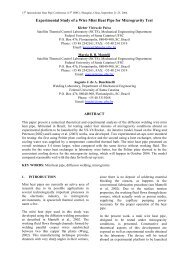
<strong>Experimental</strong> <strong>Tests</strong> <strong>of</strong> <strong>Mini</strong> <strong>Heat</strong> <strong>Pipe</strong>, <strong>Pulsating</strong> <strong>Heat</strong> <strong>Pipe</strong> <strong>and</strong> <strong>Heat</strong> Spreader under<br />
Microgravity Conditions Aboard Suborbital Rockets<br />
Kleber Vieira de Paiva, Márcia B. H. Mantelli, Leonardo Kessler Slongo, Silvio Jose Burg<br />
<strong>Heat</strong> <strong>Pipe</strong> Laboratory<br />
Mechanical Engineering Department<br />
Federal University <strong>of</strong> Santa Catarina UFSC<br />
P.O. Box 476, Florianópolis, 88040-900, SC, Brazil<br />
Phone: +55 48 2342161, FAX: +55 48 234 1519<br />
Email: kpaiva@labtucal.ufsc.br<br />
marcia@labtucal.ufsc.br<br />
leonardo@labtucal.ufsc.br<br />
jose@labtucal.ufsc.br<br />
Raul Gohr Jr., Victor Bissoli Nicolau<br />
Welding Laboratory<br />
Mechanical Engineering Department<br />
Federal University <strong>of</strong> Santa Catarina UFSC<br />
P.O. Box 476, Florianópolis, 88040-900, SC, Brazil<br />
Phone: +55 48 2342161, FAX: +55 48 234 1519<br />
Email: rgj@labsolda.ufsc.br;<br />
victor_nicolau@yahoo.com.br<br />
Abstract<br />
Consumer dem<strong>and</strong>s for electronic equipment have motivated its miniaturization <strong>and</strong> power consumption<br />
increase, leading to heat concentration problems. Small heat pipes are devices usually considered for<br />
thermal management <strong>of</strong> these systems for many terrestrial applications, including computers, laptops, etc.<br />
To guarantee a good performance <strong>of</strong> small heat pipes in microgravity conditions, the operating<br />
characteristics <strong>of</strong> these devices in this environment must be well understood.<br />
This paper presents an experimental analysis <strong>of</strong> four two-phase technologies developed in Brazil for the<br />
thermal management <strong>and</strong> heat dissipation <strong>of</strong> electronics for microgravity conditions which were tested on<br />
the laboratory (gravity environment). They are: mini heat pipes, heat spreaders, pulsating heat pipes <strong>and</strong><br />
phase change material devices (PCM), the last one used to control the heat sink temperature. These<br />
devices present not usual geometries. The tested heat pipes have been charged with acetone <strong>and</strong> methanol.<br />
The laboratory results demonstrated that the heat pipes tested present small thermal resistances <strong>and</strong> that<br />
the PCM showed to be a convenient cooling device for microgravity use. The gravity tests will be<br />
compared with microgravity results, to be obtained from a launching platform experiment flight,<br />
scheduled for 2010.<br />
Key Words: <strong>Mini</strong> heat pipe, heat spreader, pulsating heat pipe, phase change material.<br />
1. INTRODUCTION<br />
In recent years, the need for electronic<br />
components miniaturization is mainly observed in<br />
the computer industry, especially for notebooks<br />
thermal management. The compactness <strong>and</strong> high<br />
power dissipation density <strong>of</strong> these devices require<br />
efficient cooling methods. Such equipments are<br />
employed in many different applications <strong>and</strong><br />
environments, from home utilities to the<br />
International Space Station (ISS) equipment.<br />
In the normal gravity environment, heat pipe can<br />
work properly without any kind <strong>of</strong> capillary<br />
structure, if in the vertical position, or assisted by<br />
a wick material, if in the horizontal position. On<br />
the other h<strong>and</strong>, the design <strong>of</strong> these devices for<br />
operation in microgravity conditions requires an<br />
underst<strong>and</strong>ing <strong>of</strong> their operating characteristics,<br />
mainly for space applications. The thermal<br />
behavior <strong>of</strong> the two-phase thermal systems cannot<br />
be properly observed in Earth environment<br />
because gravity tends to act hard in several fluid<br />
mechanic phenomena. Actually, the gravity force<br />
can mask some effects, so that when it is<br />
decreased or even removed, other forces can<br />
assume the control <strong>of</strong> the fluid mechanics.<br />
In the search for cooling solution alternatives, four<br />
types <strong>of</strong> technologies (mini heat pipes, heat
spreaders, pulsating heat pipes <strong>and</strong> PCM),<br />
developed for the thermal management <strong>and</strong> heat<br />
dissipation under microgravity operation<br />
conditions, will be present in this work.<br />
The experiment will be tested aboard an<br />
experimental platform to be launched in the<br />
Maracati Mission <strong>of</strong> the VSB-30 rocket, from the<br />
Alcantara Rocket Launch Center in Brazil, in July<br />
2010. Around six minutes <strong>of</strong> microgravity testing<br />
time will be supplied by the Platform. Actually<br />
this launching, planned to happen in September<br />
2009, was postponed due to the launch pad<br />
rebuilding.<br />
2. <strong>Heat</strong> pipe technologies<br />
2.1 <strong>Mini</strong> heat pipes<br />
According to the previous works [1, 2 <strong>and</strong> 3], the<br />
wire mini heat pipe thermal performance can be<br />
considered known for typical flat straight<br />
geometries. But some applications require the<br />
employment <strong>of</strong> different geometries. For example,<br />
in several small laptops, curved heat pipes must<br />
be designed, to adjust to a specific geometry. In<br />
this case, the effect <strong>of</strong> bending in the thermal<br />
performance <strong>of</strong> the heat pipe must be well known,<br />
before its application. To study the influence <strong>of</strong><br />
curves in mini heat pipe performance under<br />
gravity <strong>and</strong> microgravity conditions, a “S” shape<br />
wire mini heat pipe, shown in Figure 1, was<br />
manufactured.<br />
Many different techniques can be employed for<br />
the fabrication <strong>of</strong> micro or mini heat pipes. One <strong>of</strong><br />
them consists <strong>of</strong> brazing aluminum wires between<br />
plates. This procedure can block partially the<br />
grooves formed between the wire <strong>and</strong> plates. In<br />
this work, the copper diffusion welding, a more<br />
sophisticated welding technology was used in the<br />
fabrication <strong>of</strong> the “S” shaped heat pipes [see 1, 2,<br />
3 <strong>and</strong> 4].<br />
Figure 1: “S” shaped mini heat pipe.<br />
The second technology applied for the fabrication<br />
<strong>of</strong> the mini heat pipes tested is powder sintering<br />
wick structure. As it can be seen in Figure 2, the<br />
upper <strong>and</strong> bottom plates <strong>of</strong> the MHP are covered<br />
by a thin layer <strong>of</strong> sintered copper powder porous<br />
wick. Three solid copper wires are placed in the<br />
middle <strong>of</strong> the MHP to provide a vapor region <strong>and</strong><br />
the necessary structural strength. The diffusion<br />
welding technique was employed to seal the<br />
device.<br />
Figure 2: Sintered mini heat pipe.<br />
2.2 <strong>Pulsating</strong> heat pipe<br />
The next technology tested is the pulsating heat<br />
pipe (PHP). PHP is a special type <strong>of</strong> heat pipe<br />
which works based on the displacement <strong>of</strong> the<br />
working fluid created by the evaporation <strong>and</strong><br />
condensation process, working in a nonequilibrium<br />
heat transfer state. The device<br />
manufactured for this study consists <strong>of</strong> a long<br />
copper capillary tube bent in a planar geometry<br />
(see Fig. 3) into 16 turns <strong>and</strong> charged with acetone<br />
in a volume ratio <strong>of</strong> 50%. As it does not have<br />
wicks, the vapor formed in the evaporator<br />
concentrate in several plugs, which, due to their<br />
density difference, moves to the condenser region<br />
displacing the liquid over it. Therefore, the gravity<br />
can have major influence in its performance [5].<br />
2.3 <strong>Heat</strong> Spreaders<br />
Figure 3: <strong>Pulsating</strong> heat pipe.<br />
In electronic applications, a small hot spot can<br />
cause an uneven heat flux distributions,<br />
decreasing the performance <strong>of</strong> components. In<br />
some cases, to overcome this issue, just spreading<br />
the heat can be enough to control the component<br />
temperature.<br />
Figure 4: <strong>Heat</strong> spreader.
The heat spreader proposed in this study is formed<br />
by radial grooves manufactured using wire/plate<br />
diffusion welding technique (See Figure 4). Its<br />
dimensions are: 52 mm <strong>of</strong> diameter <strong>and</strong> 2 mm <strong>of</strong><br />
thickness.<br />
3.1 TCM-A <strong>and</strong> TCM-B modules<br />
The TCM-A <strong>and</strong> TCM-B modules have the same<br />
design characteristics, where the major difference<br />
is the overall dimensions, as illustrated in Figure 6.<br />
2.4 Phase change material<br />
According to the recent microgravity experiment<br />
results [2] in rockets similar to the one to be<br />
employed in the next microgravity experiment,<br />
the temperature inside the payload model turned<br />
out to be higher than expected, due to the<br />
excessive air friction between the rocket <strong>and</strong> the<br />
atmosphere <strong>and</strong> due to heat produced by other<br />
experiments in the same module. In this way, to<br />
overcome this issue <strong>and</strong> to keep the sink<br />
temperature at steady conditions, a phase change<br />
material (PCM) device was introduced.<br />
3. EXPERIMENTAL ANALYSIS<br />
The experimental hardware dimensions are<br />
restricted due to the limited space inside the<br />
rocket platform. The experiment described in this<br />
work is composed by four models identified as<br />
TCM A, B, C <strong>and</strong> D as described in Table 1.<br />
Table 1: Equipment description.<br />
Name Description Dimensions<br />
LxWxH (mm)<br />
Mass<br />
(kg)<br />
TCM-A MHP- S shaped 285x110x210 6,03<br />
TCM-B PHP 270x90x250 7,04<br />
Figure 6: TCM-A <strong>and</strong> TCM-B modules.<br />
In these modules, an aluminum support was built<br />
to fasten the entire device in the rocket platform.<br />
Two insulation plates (polyurethane foam) are<br />
used to s<strong>and</strong>wich the heat pipes. This entire<br />
assembly is fixed to an aluminum block. Just a<br />
small part <strong>of</strong> the heat pipes (condenser) are<br />
attached to the heat sink. The aluminum block<br />
absorbs the generated heat, warming up in<br />
transient condition, as the test time is very short.<br />
Fans cannot be used in the platform due to the<br />
vibrations during the launching.<br />
Some thermistors <strong>of</strong> 10 kΏ were placed in each<br />
heat pipe to measure the temperature distribution,<br />
as can be seen in Figure 7. The thermistor<br />
temperature measurement uncertainty is ± 2ºC.<br />
TCM-C<br />
TCM-D<br />
<strong>Heat</strong> Spreader<br />
<strong>and</strong> MHP –<br />
sintered power<br />
Data acquisition<br />
system<br />
200x80x160 2,5<br />
140x146x230 5,77<br />
One <strong>of</strong> the major problems in this experiment was<br />
the space available, since the payload rocket<br />
module basically consists <strong>of</strong> a barrel with two lids,<br />
which works as experiment mounting panels (see<br />
Figure 5).<br />
Figure 5: Payload module <strong>and</strong> the experiments.<br />
Figure 7: TCM-A <strong>and</strong> B thermistors position.
3.2 TCM-C module<br />
TCM-C hardware was built in the same way as<br />
explained above for the modules TCM-A <strong>and</strong> B.<br />
The most important difference is in the heat sink.<br />
Instead <strong>of</strong> having just the aluminum block,<br />
sodium phosphate dibasic dodecahydrate will be<br />
used as an additional heat sink, absorbing the heat<br />
generated by the devices <strong>and</strong> keeping the<br />
temperature controlled (see Figure 8). This salt<br />
has a melting point <strong>of</strong> 35° C.<br />
Figure 8: TCM-C hardware.<br />
The temperatures along the device are monitored<br />
by means <strong>of</strong> thermistors (see Figure 9) that are<br />
attached to on the heat spreader.<br />
The PC/104 is basically a computer (equivalent to<br />
Pentium III, 800MHz). A MSDOS operational<br />
system is used to manage the files <strong>of</strong> the memory<br />
card. The control, read <strong>and</strong> acquisition programs<br />
were developed in C++ language. The s<strong>of</strong>tware<br />
controls great part <strong>of</strong> the experiment operation.<br />
All the data are saved in the memory card <strong>and</strong> also<br />
transmitted by telemetry. Three nickel-metal<br />
hydride battery packs, in a total <strong>of</strong> 36 V <strong>and</strong> 5Ah,<br />
are used to provide electricity to the data<br />
acquisition system as well as the heat pipes skin<br />
heaters.<br />
Due to: the short period under microgravity<br />
condition (approximately 6 minutes), the battery<br />
capacity <strong>and</strong> the platform power restrictions, only<br />
one power step will be supplied for each heat pipe,<br />
by means <strong>of</strong> electrical heaters. Table 2 describes<br />
the power applied to each heat pipe.<br />
Table 2: <strong>Mini</strong> heat pipe characteristics<br />
Module <strong>Heat</strong> pipe Volume (ml)<br />
[fluid]<br />
Power<br />
(W)<br />
MHP S 1 [methanol] 10<br />
TCM-A<br />
Sintered MHP 0.5 [methanol] 8<br />
TCM-B PHP 3.77 [acetone] 20<br />
<strong>Heat</strong> spreader 0.2 [methanol] 7<br />
TCM-C<br />
Sintered MHP 0.5 [methanol] 10<br />
3.3 Test procedure<br />
Figure 9: TCM-C thermistor positions.<br />
3.3 TCM-D module<br />
A data acquisition system was designed especially<br />
to monitor the set-up temperatures during the<br />
flight, under microgravity conditions. An<br />
aluminum box was used to accommodate the data<br />
acquisition system (see Figure 10), which is<br />
composed <strong>of</strong> the following equipments: PC/104<br />
board, data acquisition board, DC/DC converter,<br />
power control board, batteries <strong>and</strong> memory card.<br />
A control box is used to control the experimental<br />
modules. Due to the microgravity restrict time the<br />
power applied to PHP <strong>and</strong> PCM must be turned on<br />
20 minutes before the lift-<strong>of</strong>f to guarantee the PHP<br />
startup <strong>and</strong> PCM melting point. Temperatures data<br />
will be sent by RS 485 protocol to a laptop<br />
throughout an umbilical cable. Once the rocket is<br />
launched, the lift-<strong>of</strong>f sign will turn on <strong>and</strong> the data<br />
acquisition system will start to save data into the<br />
flash memory <strong>and</strong> send them by telemetry, at the<br />
same time. Approximately 1 minute after the lift<strong>of</strong>f,<br />
the microgravity condition will be reached<br />
<strong>and</strong> an electrical signal will power up the rest <strong>of</strong><br />
the heat pipes.<br />
During the lift-<strong>of</strong>f step, the cables that will be<br />
connected to the rocket umbilical will be removed,<br />
commuting the experiment to the automatic mode<br />
<strong>and</strong> using energy from the batteries. For the<br />
laboratory tests, the same procedure was followed.<br />
4. EXPERIMENTAL RESULTS<br />
Figure 10: Data acquisition module.<br />
The test results under gravity conditions are<br />
presented in this section. Figure 11 shows the<br />
performance <strong>of</strong> the “S” shaped mini heat pipe.<br />
Figure 12 shows the PHP results. From this last<br />
figure, one can observe that it takes a while for the
temperatures to start to oscillate <strong>and</strong> that this<br />
oscillation is more observed in the adiabatic<br />
section. As illustrated in both Figures 11 <strong>and</strong> 12,<br />
the devices did not reach the steady state<br />
conditions, due to the small capacity <strong>of</strong> the<br />
aluminum heat sink, which keeps heating up while<br />
they receive heat from the experiments. Even<br />
though, the performance <strong>of</strong> this heat pipes are<br />
almost the same when their results were compared<br />
with the laboratory results, using the cooling bath<br />
apparatus as a heat sink.<br />
Temperature (°C)<br />
60<br />
50<br />
40<br />
30<br />
20<br />
TC 1 - condenser<br />
TC 2 - condenser<br />
TC 3 - adiabatic section<br />
TC 4 - adiabatic section<br />
TC 5 - evaporator<br />
TC 6 - evaporator<br />
TC 7 - heater<br />
10<br />
0 500 1000 1500 2000<br />
Time (s)<br />
Figure 11: Gravity temperature pr<strong>of</strong>ile <strong>of</strong> the “S”<br />
mini heat pipe.<br />
Temperature (°C)<br />
60<br />
50<br />
40<br />
30<br />
20<br />
TC 16 - evaporator<br />
TC 17 - evaporator<br />
TC 18 - evaporator<br />
TC 19 - adiabatic section<br />
TC 20 - adiabatic section<br />
TC 21 - adiabatic section<br />
TC 22 - condenser<br />
TC 23 - condenser<br />
TC 24 - condenser<br />
Figure 13 shows the heat spreader results. As<br />
can be observed, during the first 20 minutes<br />
(around 1250 seconds), power was applied to<br />
the aluminum block heaters in order to melt the<br />
PCM. As soon as the steady state is reached,<br />
heat is added to the device. Similar temperatures<br />
are observed by the thermistors distributed<br />
along the heat spreader, showing an even<br />
temperature distribution.<br />
Temperature (°C)<br />
60<br />
50<br />
40<br />
30<br />
20<br />
TC 33 - condenser<br />
TC 34 - adiabatic section<br />
TC 35 - evaporator<br />
TC 36 - heater<br />
10<br />
0 500 1000 1500 2000<br />
Time (s)<br />
Figure 14: Gravity temperature pr<strong>of</strong>ile <strong>of</strong> the<br />
sintered mini heat pipe with PCM in the heat<br />
sink.<br />
Temperature (°C)<br />
60<br />
50<br />
40<br />
30<br />
20<br />
T33_condenser<br />
T34_adiabatic section<br />
T35_evaporator<br />
T36_heater<br />
10<br />
0 500 1000 1500 2000<br />
Time (s)<br />
Figure 12: Gravity temperature pr<strong>of</strong>ile <strong>of</strong> the PHP.<br />
70<br />
10<br />
0 500 1000 1500 2000<br />
Time (s)<br />
Figure 15: Gravity temperature pr<strong>of</strong>ile <strong>of</strong> the<br />
sintered mini heat pipe without PCM in the heat<br />
sink.<br />
Temperature (°C)<br />
60<br />
50<br />
40<br />
30<br />
TC 29 - heater<br />
TC 30<br />
TC 31<br />
TC 32<br />
Comparing Figures 14 <strong>and</strong> 15, one can see that the<br />
PCM, used as an additional heat sink for the<br />
sintered MHP experiment, stabilizes the<br />
temperature distribution, allowing the system to<br />
reach the steady state conditions.<br />
4. CONCLUSIONS<br />
20<br />
10<br />
0 500 1000 1500 2000<br />
Time (s)<br />
Figure 13: Gravity temperature pr<strong>of</strong>ile <strong>of</strong> the<br />
heat spreader using PCM in the heat sink.<br />
The heat transfer performance <strong>of</strong> four types <strong>of</strong><br />
heat pipes have been investigated experimentally<br />
under gravity conditions. Unfortunately the<br />
microgravity test was postponed <strong>and</strong> so the<br />
comparison <strong>of</strong> gravity <strong>and</strong> microgravity
experimental results could not presented in this<br />
paper.<br />
PCM showed to be a good alternative as heat sink<br />
for this kind <strong>of</strong> experiment to be tested aboard<br />
sounding rockets. The temperature pr<strong>of</strong>iles<br />
indicate that the use <strong>of</strong> the aluminum block as the<br />
heat sink was not enough to allow the system to<br />
reach steady state conditions.<br />
The observed thermal resistances <strong>of</strong> the devices<br />
tested in laboratory are small, showing that the<br />
technologies applied are efficient <strong>and</strong> that these<br />
heat pipes can be used as an electronic equipment<br />
thermal control devices for gravity <strong>and</strong> very<br />
probably for microgravity applications.<br />
REFERENCES<br />
1. Paiva, K. V. ; Mantelli, M. B.; Gohr, R. ;<br />
Correa, M. A. . Wire mini heat pipe under<br />
microgravity conditions. In: 14th International<br />
<strong>Heat</strong> <strong>Pipe</strong> Conference (14th IHPC), 2007,<br />
Florianópolis-SC-Brazil.<br />
2. Paiva, K. V.; Comportamento térmico em<br />
gravidade e microgravidade de mini tubos de<br />
calor do tipo fio-placas, Universidade Federal<br />
de Santa Catarina, Florianópolis, Brazil, 2007 -<br />
dissertation.<br />
3. Launay, S.; Sartre, V.; Mantelli, M.B.H.; Paiva,<br />
K.V., Investigation <strong>of</strong> a wire plate micro heat<br />
pipe array, International Journal <strong>of</strong> Thermal<br />
Sciences, vol. 43, Issue 5, pp 499-507, May<br />
2004.<br />
4. Wang, Y.X., Peterson, G.P., 2002, Analysis <strong>of</strong><br />
Wire-Bonded Micro <strong>Heat</strong> <strong>Pipe</strong>, Journal <strong>of</strong><br />
Thermophysics <strong>and</strong> <strong>Heat</strong> Transfer, Vol.12,<br />
No.3, pp 346-355.<br />
5. Kh<strong>and</strong>ekar, S., 2004, An insight into thermohydrodynamic<br />
coupling in closed loop<br />
pulsating heat pipes, International Journal <strong>of</strong><br />
Thermal Sciences, Vol. 43, No. 1, pp. 13-20.