Thermal applicability of two-phase thermosyphons in ... - LEPTEN
Thermal applicability of two-phase thermosyphons in ... - LEPTEN
Thermal applicability of two-phase thermosyphons in ... - LEPTEN

Create successful ePaper yourself
Turn your PDF publications into a flip-book with our unique Google optimized e-Paper software.
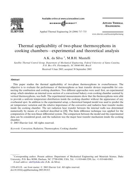
Applied <strong>Thermal</strong> Eng<strong>in</strong>eer<strong>in</strong>g 24 (2004) 717–733www.elsevier.com/locate/apthermeng<strong>Thermal</strong> <strong>applicability</strong> <strong>of</strong> <strong>two</strong>-<strong>phase</strong> <strong>thermosyphons</strong> <strong>in</strong>cook<strong>in</strong>g chambers––experimental and theoretical analysisA.K. da Silva * , M.B.H. MantelliSatellite <strong>Thermal</strong> Control Group, Department <strong>of</strong> Mechanical Eng<strong>in</strong>eer<strong>in</strong>g, Federal University <strong>of</strong> Santa Catar<strong>in</strong>a,P.O. Box 476, Florianopolis, SC 88040-900, BrazilReceived 9 June 2003; accepted 30 September 2003AbstractThis paper studies the thermal <strong>applicability</strong> <strong>of</strong> <strong>two</strong>-<strong>phase</strong> <strong>thermosyphons</strong> <strong>in</strong> ovens/furnaces. Theobjective is to evaluate the performance <strong>of</strong> <strong>thermosyphons</strong> as heat transfer devices responsible for connect<strong>in</strong>gthe combustion and cook<strong>in</strong>g chambers. Two different approaches were used: first, an experimentalsetup, which simulates an <strong>in</strong>ternal cross section <strong>of</strong> a convectional bakery oven cook<strong>in</strong>g chamber assisted byvertical <strong>thermosyphons</strong>, was built. The experimental measurements show that the <strong>thermosyphons</strong> were ableto provide a uniform temperature distribution <strong>in</strong>side the cook<strong>in</strong>g chamber without the appearance <strong>of</strong> anyoverheated spot. In addition to the experimental setup, a theoretical lumped model was used to predict theair temperature variation and the relative importance <strong>of</strong> the convective and radiative heat transfer modes<strong>in</strong>side the cook<strong>in</strong>g chamber. The net radiation heat transfer between the <strong>in</strong>ternal walls was determ<strong>in</strong>ednumerically by means <strong>of</strong> a method described <strong>in</strong> [20]. The f<strong>in</strong>ite difference technique was applied for thecomputation <strong>of</strong> the non-l<strong>in</strong>ear differential system. The comparison between the model and the experimentaldata can be considered good, and the radiation was the major heat transfer mechanism <strong>in</strong>side the cook<strong>in</strong>gchamber.Ó 2003 Elsevier Ltd. All rights reserved.Keywords: Convection; Radiation; Thermosyphon; Cook<strong>in</strong>g chamber* Correspond<strong>in</strong>g author. Present address: Department <strong>of</strong> Mechanical Eng<strong>in</strong>eer<strong>in</strong>g and Materials Science, DukeUniversity, P.O. Box 90300, Durham, NC 27708-0300, USA. Tel.: +1-919-660-5299; fax: +1-919-660-8963.E-mail address: akd3@duke.edu (A.K. da Silva).1359-4311/$ - see front matter Ó 2003 Elsevier Ltd. All rights reserved.doi:10.1016/j.applthermaleng.2003.09.013
718 A.K. da Silva, M.B.H. Mantelli / Applied <strong>Thermal</strong> Eng<strong>in</strong>eer<strong>in</strong>g 24 (2004) 717–733NomenclatureA area, m 2b thickness, mC global conductance, W m 1 K 1c p specific heat, J kg 1 K 1F view factorg gravity, m s 2G yield radiation coefficienth heat transfer coefficient, W m 2 K 1H height, mI current, Ak thermal conductivity, W m 1 K 1L length, mNu L average Nusselt numberP experimental power applied, Wq 0 heat flux, W m 1^q dimensionless heat fluxQ heat transfer rate, WPr Prandtl numberRe Reynolds numbert time, s^t dimensionless timeT temperature, °CT average temperature, °CU overall heat transfer coefficient, W m 2 K 1v characteristic velocity, m s 1V volume, m 3 , voltage, Vx, y, z Cartesian coord<strong>in</strong>ates, mGreek symbolsa absorptivity, thermal difussivity, m 2 s 1e emissivitym k<strong>in</strong>ematic viscosity, m 2 s 1q reflectivityr Stefan–Boltzmann constant, W m 2 K 4Subscripts1, 2, 3, 4 <strong>in</strong>ternal surfaces <strong>in</strong>dexair enclosed airavg, e average externalavg, i average <strong>in</strong>ternale evaporator
A.K. da Silva, M.B.H. Mantelli / Applied <strong>Thermal</strong> Eng<strong>in</strong>eer<strong>in</strong>g 24 (2004) 717–733 719c condenserconv convectivefilm film temperaturei; j; ...; N surface general <strong>in</strong>dexI <strong>in</strong>sulationL characteristic lengthms metal sheetout outside the cook<strong>in</strong>g chamberrad radiative1. IntroductionEnergy generation and conservation has received special attention all over the world. This is thema<strong>in</strong> concern <strong>of</strong> several <strong>in</strong>dustries that are forced to save energy and reduce the production costs[1]. Good examples are the companies that produce electric bakery ovens, s<strong>in</strong>ce the energy consumption<strong>in</strong> such devices is an important issue, especially for small bus<strong>in</strong>ess. Besides this economicfactor, which can be related to performance, functionality is also a major issue. The thermalcharacteristics <strong>of</strong> the actual ovens do not provide a uniform temperature distribution <strong>in</strong>side thecook<strong>in</strong>g chamber. Usually these ovens have an electrical resistance located <strong>in</strong>side the cook<strong>in</strong>gchamber. The resistance (i.e., heat source) has a small heat transfer area when compared with thevolume to be heated, which creates over-heated regions. Spread<strong>in</strong>g out the heat sources <strong>in</strong>side theovenÕs cook<strong>in</strong>g chamber can easily solve this problem, although it is too expensive.As an alternative solution, big blowers are <strong>in</strong>stalled <strong>in</strong>side the cook<strong>in</strong>g chamber <strong>in</strong> order to turnthe temperature uniform. However, big electric motors consume lots <strong>of</strong> energy itself, and <strong>in</strong> spite<strong>of</strong> that it is known that radiation is the major heat transfer mechanism <strong>in</strong>side enclosures [2–9].Carvalho and Mart<strong>in</strong>s [10] performed a very specific numerical study consider<strong>in</strong>g a threedimensionalturbulent flow <strong>of</strong> air and steam <strong>in</strong>side a cook<strong>in</strong>g chamber, emphasiz<strong>in</strong>g the heat andmass transfer modes. They stressed the importance <strong>of</strong> the radiative heat flux as a major mechanism,show<strong>in</strong>g that the radiation represents more than 70% <strong>of</strong> the total energy absorbed by thebread dough <strong>in</strong>side the oven at a cook<strong>in</strong>g temperature equal to 200 °C. Based on that we canconclude that the ideal situation is the one <strong>in</strong> which the heat sources <strong>in</strong>side the cook<strong>in</strong>g chamberhave large areas and temperatures slightly greater than the ideal cook<strong>in</strong>g temperature. Based onsuch conclusion, how can we come up with a solution thermally and economically viable?To answer this question, the Satellite <strong>Thermal</strong> Control Group (NCTS) is study<strong>in</strong>g the use <strong>of</strong> <strong>two</strong><strong>phase</strong><strong>thermosyphons</strong> <strong>in</strong> ovens work<strong>in</strong>g as a heat transfer device, which connects thermally thecombustion and cook<strong>in</strong>g chambers. Several studies have been reported demonstrat<strong>in</strong>g the successful<strong>applicability</strong> <strong>of</strong> <strong>thermosyphons</strong> <strong>in</strong> other applications [11–16]. However, for the first time, vertical<strong>thermosyphons</strong> with an unusual geometry (i.e., <strong>thermosyphons</strong> where the condenser is five timeslarger than the evaporator <strong>in</strong> length) have been used <strong>in</strong> ovens. A prelim<strong>in</strong>ary study by Mantelli et al.[17] showed that the new geometric configuration used <strong>in</strong> the present study, which is required to athermosyphon to ‘‘fit’’ <strong>in</strong>side a convectional oven, presents a good thermal performance.
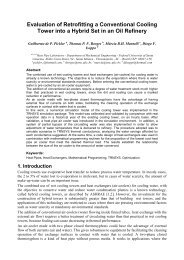
720 A.K. da Silva, M.B.H. Mantelli / Applied <strong>Thermal</strong> Eng<strong>in</strong>eer<strong>in</strong>g 24 (2004) 717–733In the present work, we proposed to <strong>in</strong>vestigate the behavior <strong>of</strong> <strong>thermosyphons</strong> exposed to realconditions <strong>in</strong> cook<strong>in</strong>g chambers. For that, an experimental prototype, which simulates the crosssection <strong>of</strong> the commercial oven, was built. Four vertical <strong>thermosyphons</strong> were <strong>in</strong>stalled <strong>in</strong>side theprototype. The experimental measurements were compared with the results generated by a theoreticallumped model, which takes <strong>in</strong>to account the convective and radiative effects <strong>in</strong>side thecook<strong>in</strong>g chamber.2. Theoretical modelIn the present model, a transient heat transfer balance between the <strong>in</strong>ternal surfaces <strong>of</strong> acook<strong>in</strong>g chamber and the enclosed air is performed. The physical model described <strong>in</strong> Fig. 1 isbased on the experimental setup built by NCTS, later <strong>in</strong> this study. The <strong>in</strong>teraction among thefour <strong>in</strong>ternal walls is taken <strong>in</strong>to account. The enclosure is filled with air, which is considered anon-participat<strong>in</strong>g gas <strong>in</strong> the radiation net. The radiation scatter<strong>in</strong>g is neglected and the forcedconvection flow <strong>in</strong> the <strong>in</strong>ternal walls is considered well mixed. The relative <strong>in</strong>fluence <strong>of</strong> the wallradiation properties and the forced convection, represented by the Reynolds number (Re ¼ vL=m),are exam<strong>in</strong>ed, where v represents a characteristic velocity (i.e., the mean flow velocity over areferred plate), L is the characteristic length <strong>of</strong> the plate and m is the k<strong>in</strong>ematic viscosity.This model consists <strong>of</strong> the heat transfer balance among the air <strong>in</strong>side the cook<strong>in</strong>g chamber, thetop and bottom horizontal surfaces, and <strong>two</strong> vertical lateral surfaces. The air temperature wasnamed T air , and the temperature <strong>of</strong> the top and bottom surfaces were named T 2 and T 4 respectively.The vertical walls surfaces temperatures, T 1 and T 3 , are considered equal and prescribed,vary<strong>in</strong>g accord<strong>in</strong>g to the experimental data, described later <strong>in</strong> this study. The conduction heattransfer between the <strong>in</strong>ternal walls and the heat losses between the vertical walls and the exteriorenvironment are neglected. On the other hand, heat transfer between the horizontal walls and theoutside environment is considered. The overall heat transfer coefficients between the horizontalLq' U2L2(ToutT2)T 3T 2∂T ∂T = 0= 0∂x∂xT 1yT 4T airT outHxq' U4L4(ToutT4)Fig. 1. Theoretical physical model for the enclosure with transient temperatures.
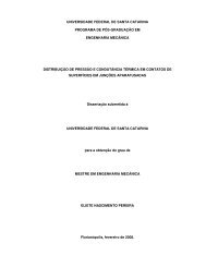
A.K. da Silva, M.B.H. Mantelli / Applied <strong>Thermal</strong> Eng<strong>in</strong>eer<strong>in</strong>g 24 (2004) 717–733 721walls and the environment were named U 2 and U 4 . They are concerned with the top and bottomwalls respectively.The transient heat exchange between the walls and the air happens through convection, whilethe transient heat transfer between the <strong>in</strong>ternal walls is through convection and radiation. Theheat balance for the enclosed air is given bydT airq air c p;air V air ¼ 2h 1 A 1 ½T 1 T air Šþh 2 A 2 ½T 2 T air Šþh 4 A 4 ½T 4 T air Š ð1ÞdtIn the above equation, the three right hand side terms represent the energy obta<strong>in</strong>ed by forcedconvection from the surfaces 1, 2 and 4 respectively. The convective heat transfer coefficientsbetween the walls and the air, h 1 , h 2 and h 4 , are functions <strong>of</strong> the respective wallÕs temperature, andwere calculated accord<strong>in</strong>g to the film temperature <strong>of</strong> each surface. For surfaces 1 and 3, the filmtemperature is def<strong>in</strong>ed as T film;1 ¼ðT 1 T air Þ=2, for surface 2, T film;2 ¼ðT 2 T air Þ=2, and f<strong>in</strong>ally forsurface 4, T film;4 ¼ðT 4 T air Þ=2. A 1 , A 2 and A 4 , are the <strong>in</strong>ternal surface areas for the vertical, topand bottom walls respectively. The three left hand side parameters (q air ; c p;air and V air ) are thedensity, the specific heat and the volume <strong>of</strong> the air <strong>in</strong>side the enclosure.Another balance given by Eq. (2), evaluates the temperature variation <strong>of</strong> surface 2 consider<strong>in</strong>gthree effects. On the right hand side, the first term represents the convective heat transfer betweenthis surface and the <strong>in</strong>side air, the second term determ<strong>in</strong>es the heat losses to the outside environment,and the third term represents the liquid radiation heat flux reach<strong>in</strong>g this surface. Asimilar energy balance is obta<strong>in</strong>ed for surface 4, and it is given by Eq. (3), where the same threeterms described for Eq. (2) can be found. Eqs. (1)–(3) form a non-l<strong>in</strong>ear and non-homogeneoussystem <strong>of</strong> differential equations.q 2 c P;2 V 2dT 2dt¼ h 2 A 2 ðT air T 2 ÞþU 2 A 2 ðT out T 2 Þþ X4i¼1A 2 e 2 rG 2 i T 4iT 4 2ð2Þq 4 c P;4 V 4dT 4dt¼ h 4 A 4 ðT air T 4 ÞþU 4 A 4 ðT out T 4 Þþ X4i¼1A 4 e 4 rG 4 i T 4iT 4 4ð3ÞIn Eqs. (2) and (3), the <strong>two</strong> overall coefficients, U 2 and U 4 , take <strong>in</strong>to account the heat transferthrough the <strong>in</strong>ternal metal sheet, the prototype <strong>in</strong>sulation layer, the external metal sheet and theoutside convection heat transfer. Figure 2 gives a detailed view <strong>of</strong> the top surface. These overallcoefficients are def<strong>in</strong>ed <strong>in</strong> Eqs. (4) and (5):q' U2L2(ToutT2)InsulationMetal SheetbmsbICook<strong>in</strong>g ChamberFig. 2. Top surface <strong>in</strong>sulation detail.
722 A.K. da Silva, M.B.H. Mantelli / Applied <strong>Thermal</strong> Eng<strong>in</strong>eer<strong>in</strong>g 24 (2004) 717–733 U 2 ¼ 2 b msþb 1I 1þð4Þk ms k I h out;2 U 4 ¼ 2 b msþk msb Ik Iþ 11ð5Þh out;4The conductivity <strong>of</strong> the metal sheets and the <strong>in</strong>sulation layer were considered constant and equalfor the top and bottom walls. The outside convection heat transfer coefficients, h out;2 and h out;4 ,were based on a well-known literature correlation for horizontal plates subjected to naturalconvection [18]. The temperatures used <strong>in</strong> the correlations were based on the experimental meantemperatures <strong>of</strong> the external metal sheets, which covers the top and bottom surfaces. The meanvalue for the heat transfer coefficients were found to be equal to 1.7 and 1.0 [W/m 2 K] for theexternal sheets that cover the top and bottom surfaces <strong>of</strong> the prototype respectively.The convective heat transfer coefficients h 1 , h 2 , and h 4 , presented <strong>in</strong> Eqs. (1)–(3), were determ<strong>in</strong>edaccord<strong>in</strong>g to the follow<strong>in</strong>g expression, as described <strong>in</strong> [19]:Nu L ¼ 0:037Re 4=5L Pr1=3 ; Pr P 0:5 ð6Þwhere Re L is the Reynolds number, and Pr is the Prandtl number. This correlation is valid for amixed lam<strong>in</strong>ar and turbulent flow over a flat plate. The mixed flow regime is a reasonableassumption, s<strong>in</strong>ce four small ventilators were used close to the bottom and the top walls to promotea turbulent <strong>in</strong>ternal flow <strong>in</strong> the experimental setup.The theoretical prescribed temperature <strong>of</strong> surfaces 1 and 3 was obta<strong>in</strong>ed by sett<strong>in</strong>g T 1 and T 3equal to the average temperature read<strong>in</strong>gs <strong>of</strong> the four condensers <strong>of</strong> the <strong>thermosyphons</strong> used <strong>in</strong>the experimental prototype. Based on these experimental data, a theoretical expression for thetemperatures T 1 and T 3 was adjusted as a function <strong>of</strong> time. Such function ruled the heat<strong>in</strong>g processon the theoretical model. The agreement <strong>of</strong> the adjusted function and the experimental data canbe considered good, with deviations no larger than ±2 °C.At this po<strong>in</strong>t, the net radiation heat exchange needs to be addressed to Eqs. (2) and (3), and theenergy absorbed by any <strong>in</strong>ternal surface has to be determ<strong>in</strong>ed. For this analysis, the methoddescribed <strong>in</strong> [20] was applied. Let us consider a coefficient named G jk , which represents thefraction <strong>of</strong> radiative energy emitted from surface A j that reaches and is absorbed by surface A k .The G jk coefficient cannot be zero, s<strong>in</strong>ce even for a convex surface, some radiative energy will bereturned to itself by reflection from other surfaces. Consider<strong>in</strong>g A j e j rTj 4Gjk as the fraction <strong>of</strong>energy emitted by the surface A j , which is absorbed by A k , the liquid heat flux for the surface A k isQ k ¼ A k e k rT 4 kðA 1 e 1 rT 4 1 G 1k þ A 2 e 2 rT 4 2 G 2k þþA j e j rT 4j G jk þþA k e k rT 4 k G kk þþ A N e N rT 4 N G NkÞOn the other hand, know<strong>in</strong>g that the total energy emitted from A j is A j e j rTj 4 , we can say that theportion that reaches A k directly and is absorbed is A j e j rTj 4Fj ke k , where F j k is the view factorbetween the surfaces j and k, and e k ¼ a k for a gray surface. It is important to note that all otherradiative energy emitted from A j and arriv<strong>in</strong>g at A k , will undergo to at least one reflection.Generaliz<strong>in</strong>g, we can evaluate the radiation from A j that arrives to any typical surface such as A N ,and it is reflected as A j e j rTj 4Fj Nq N , where q N is the reflectivity <strong>of</strong> the surface N. Only the G Nk heatð7Þ
fraction reaches A k and is absorbed. Therefore, all the energy fractions absorbed at A k that isorig<strong>in</strong>ated from A j isQ kj ¼ A j e j rT 4ke kj F j|fflfflfflfflfflfflfflfflffl{zfflfflfflfflfflfflfflfflffl}Energy absorbeddirectlyþðA j e j rT 4j F j 1q 1 G 1k þA j e j rT 4j F j 2q 2 G 2k þþA j e j rT 4j F j kq k G kk þA j e j rT 4j F j Nq N G Nk Þ|fflfflfflfflfflfflfflfflfflfflfflfflfflfflfflfflfflfflfflfflfflfflfflfflfflfflfflfflfflfflfflfflfflfflfflfflfflfflfflfflfflfflfflfflfflfflfflfflfflfflfflfflfflfflfflfflfflfflfflfflfflfflfflfflfflfflfflfflfflfflfflfflfflfflfflfflfflfflffl{zfflfflfflfflfflfflfflfflfflfflfflfflfflfflfflfflfflfflfflfflfflfflfflfflfflfflfflfflfflfflfflfflfflfflfflfflfflfflfflfflfflfflfflfflfflfflfflfflfflfflfflfflfflfflfflfflfflfflfflfflfflfflfflfflfflfflfflfflfflfflfflfflfflfflfflfflfflfflffl}Energy absorbed<strong>in</strong>directlyThe G ij coefficient can be determ<strong>in</strong>ed by the expression result<strong>in</strong>g from the sum <strong>of</strong> the total energyemitted by A j and Eq. (8), which results <strong>in</strong>G jk ¼ F j k e k þ F j 1 q 1 G 1k þ F j 2 q 2 G 2k þþF j k q k G kk þþF j N q N G Nk ð9ÞIf Eq. (9) is applied to all k surfaces <strong>of</strong> the enclosure, a system <strong>of</strong> equations, which has to be solvedfor G 1k ; G 2k ; ...G Nk , will be formed. This system can be represented by the matricial equation,½G jk Š¼½m 1 Š½f Š. For the present case, m and f arem ¼264A.K. da Silva, M.B.H. Mantelli / Applied <strong>Thermal</strong> Eng<strong>in</strong>eer<strong>in</strong>g 24 (2004) 717–733 723ð1 F 1-1 q 1 Þ F 1-2 q 2 F 1-3 q 3 F 1-4 q 4F 2-1 q 1 ð1 F 2-2 q 2 Þ F 2-3 q 3 F 2-4 q 4F 3-1 q 1 F 3-2 q 2 ð1 F 3-3 q 3 Þ F 3-4 q 4F 4-1 q 1 F 4-2 q 2 F 4-3 q 3 ð1 F 4-4 q 4 Þ3ð8Þ75 ð10Þ23F 1-1 e 1 F 1-2 e 2 F 1-3 e 3 F 1-4 e 4Ff ¼ 2-1 e 1 F 2-2 e 2 F 2-3 e 3 F 2-4 e 4674 F 3-1 e 1 F 3-2 e 2 F 3-3 e 3 F 3-4 e 45 ð11ÞF 4-1 e 1 F 4-2 e 2 F 4-3 e 3 F 4-4 e 4The explicit f<strong>in</strong>ite difference approximation was used for the time derivative <strong>of</strong> the temperature <strong>of</strong>the air and the surfaces 2 and 4 that appear <strong>in</strong> Eqs. (1)–(3). The discretized result<strong>in</strong>g non-l<strong>in</strong>earsystem was solved numerically us<strong>in</strong>g the mathematical s<strong>of</strong>tware MAPLE. The time <strong>in</strong>tervalbetween <strong>two</strong> consecutive iterations was one second, Dt ¼ 1 s. The process<strong>in</strong>g time was around45 m<strong>in</strong> us<strong>in</strong>g a computer with 1 GHz processor and 512 Mb RAM. Table 1 conta<strong>in</strong>s the values <strong>of</strong>the thermophysical properties used <strong>in</strong> the computation <strong>of</strong> the equations above.Table 1Thermophysical properties and parameters used <strong>in</strong> the theoretical modelAverage specific heat <strong>of</strong> air (c p;air ) 1000 J kg 1 K 1Average specific heat <strong>of</strong> the metals sheets (c p;1-4 ) 440 J kg 1 K 1Density <strong>of</strong> dry air (q air ) 1 kg m 3Density <strong>of</strong> metal sheets (q 1-4 ) 7850 kg m 3Emissivity <strong>of</strong> metal sheets (e 1-4 ) 0.2Global heat transfer coefficient––top surface (U 2 ) 1.7 W m 2 K 1Global heat transfer coefficient––bottom surface (U 4 ) 1 Wm 2 K 1Metal sheet thermal conductivity 45 W m 1 K 1Dry air thermal conductivity 0.035 W m 1 K 1Stefan–Boltzmann constant (r) 5.7 · 10 8 Wm 2 K 4Metal sheet thickness (b ms )0.002 mInsulation thickness (b I )0.0254 mOutside environment surface (T out ) 25 °C
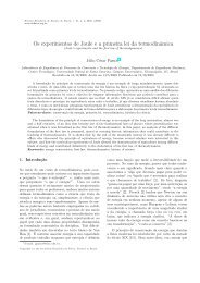
724 A.K. da Silva, M.B.H. Mantelli / Applied <strong>Thermal</strong> Eng<strong>in</strong>eer<strong>in</strong>g 24 (2004) 717–7333. Experimental apparatusAs a second part <strong>of</strong> this study, an experimental prototype was build at Federal University <strong>of</strong>Santa Catar<strong>in</strong>a aim<strong>in</strong>g to determ<strong>in</strong>e the real <strong>applicability</strong> <strong>of</strong> <strong>two</strong>-<strong>phase</strong> <strong>thermosyphons</strong> as a heattransfer devices between the combustion and cook<strong>in</strong>g chambers. Instead <strong>of</strong> us<strong>in</strong>g a real sizeprototype, an <strong>in</strong>ternal section (i.e., a ‘‘slice’’) <strong>of</strong> a commercial oven was experimentally simulated.The prototype has a cross section area <strong>of</strong> 1270 mm (height) · 800 mm (width) <strong>in</strong>clud<strong>in</strong>g the<strong>in</strong>sulation, which was made <strong>of</strong> a special fiber for high temperatures, and was 25 mm thick on thetop and bottom surfaces and 50 mm thick <strong>in</strong> each vertical wall. The <strong>in</strong>sulation configuration isshown <strong>in</strong> detail <strong>in</strong> Fig. 2.Sta<strong>in</strong>less steel/water <strong>thermosyphons</strong> were <strong>in</strong>stalled vertically close to <strong>two</strong> lateral walls <strong>of</strong> thissection. To improve the heat exchange, sta<strong>in</strong>less steel f<strong>in</strong>s are coupled to the <strong>thermosyphons</strong> asshown <strong>in</strong> Fig. 3. The sta<strong>in</strong>less steel material was selected due to its strength and durability whensubmitted to <strong>in</strong>ternal high pressures. Also, the sta<strong>in</strong>less steel is a convenient material for the food<strong>in</strong>dustry. Water was chosen as the work<strong>in</strong>g fluid because it is safe and cheap, present<strong>in</strong>g a goodbehavior <strong>in</strong> terms <strong>of</strong> heat transfer capacity for the temperature work<strong>in</strong>g range around 300 °C[21,22]. The <strong>thermosyphons</strong> used <strong>in</strong> the prototype present an unusual geometry as described <strong>in</strong> [17].Accord<strong>in</strong>g to Mantelli et al. [17], such a configuration <strong>of</strong> the thermosyphon presented a good thermalbehavior with a temperature difference between the condenser and evaporator less than 20 °C.The <strong>thermosyphons</strong> have 1220 mm <strong>of</strong> total length, where 1000 mm corresponds to the condenser,200 mm to the evaporator and 20 mm to the adiabatic section. Their external diametersThermosyphonsCondenser-AdiabaticSectionEvaporatorSk<strong>in</strong>HeaterF<strong>in</strong>sW<strong>in</strong>dowGuardHeateryzFansxSimulatedSectionCommercial OvenFig. 3. Experimental setup sketch.
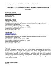
A.K. da Silva, M.B.H. Mantelli / Applied <strong>Thermal</strong> Eng<strong>in</strong>eer<strong>in</strong>g 24 (2004) 717–733 725are 19.05 mm and the fill<strong>in</strong>g ratio is 60% <strong>of</strong> the evaporator volume [22–24]. The power was appliedmanually and varied between 50 and 200 W per evaporator, <strong>in</strong> 50 W steps <strong>of</strong> 30 m<strong>in</strong> each. Theheat was delivered to the evaporator by an electrical sk<strong>in</strong> heater built <strong>in</strong> order to mimic a combustionchamber. The sk<strong>in</strong> heater was made <strong>of</strong> a flat wire electrical resistance sandwiched by <strong>two</strong>layers <strong>of</strong> an appropriated electrical <strong>in</strong>sulator. The experimental temperature limit was selectedequal to 260 °C at any po<strong>in</strong>t <strong>in</strong> the evaporator. At this temperature level the sk<strong>in</strong> heater electrical<strong>in</strong>sulation starts to degrade, risk<strong>in</strong>g the whole apparatus. The four fans <strong>in</strong>stalled <strong>in</strong>side the prototypeprovided the mixed convection regime <strong>in</strong>side the cook<strong>in</strong>g chamber. Two <strong>of</strong> them were<strong>in</strong>stalled close to the bottom surface, and the other <strong>two</strong> were fixed closed to the top surface <strong>in</strong>order to prevent any excessive thermal stratification. These fans are the exact same model used tocool down computer; hence, they have low power.S<strong>in</strong>ce we are simulat<strong>in</strong>g just a ‘‘slice’’ <strong>of</strong> a real oven, electric guards heaters were <strong>in</strong>stalled onthe exterior side <strong>of</strong> the frontal and back walls to ma<strong>in</strong>ta<strong>in</strong> the front and back walls adiabatic. Theguard heaters were fabricated with the same resistive flat wire used as a sk<strong>in</strong> heater on the<strong>thermosyphons</strong>Õ evaporators. Figure 3 shows that the distance between the flat wires is smaller onthe top <strong>of</strong> the front and back walls. This was required due to a slightly experimental temperaturegradient found on y-direction.Approximately 30 thermocouples type K where <strong>in</strong>stalled on the prototype for the temperaturemeasurement <strong>of</strong> the heated air and <strong>in</strong>ternal walls. About five thermocouples were <strong>in</strong>stalledequidistantly on each thermosyphon, <strong>two</strong> on each the evaporator and three on each condenser.These thermocouples were connected to a Hewlett Packard-34970A acquisition data system,which was connected to a computer. The read<strong>in</strong>gs were made every one second. Us<strong>in</strong>g theseread<strong>in</strong>gs, the prototype temperatures were determ<strong>in</strong>ed and compared with the theoretical modeldescribed <strong>in</strong> Section 2.Figure 4 shows the comparison between the mean <strong>in</strong>ternal and external temperatures <strong>of</strong> thefront wall. We can see that the temperature levels are very similar, show<strong>in</strong>g that negligible heat isbe<strong>in</strong>g transferred throughout the wall. In other words, the guard heater proved to be efficient. Asimilar curve can be observed for the rear vertical wall, but it will not be presented here. Thedisagreement found around 140 °C is due to a limitation <strong>of</strong> the guard heater power supply.The electric power applied to each thermosyphon is shown <strong>in</strong> Fig. 5. In the same figure theliquid power applied, which is def<strong>in</strong>ed as the total applied heat m<strong>in</strong>us the heat losses, is alsoshown. The heat losses always represent less than 8% <strong>of</strong> the total electric power. They weredeterm<strong>in</strong>ed by account<strong>in</strong>g the temperature difference between the evaporatorsÕ external thermal<strong>in</strong>sulation surface and the environment.4. Experimental uncerta<strong>in</strong>tyThe applied power <strong>in</strong> the evaporators and <strong>in</strong> the guard heater were calculated from theexpression, P ¼ V I, which is also used to determ<strong>in</strong>e the power uncerta<strong>in</strong>ty. The uncerta<strong>in</strong>ty <strong>of</strong>the <strong>in</strong>dependent variables I ¼ 10 0:01 and V ¼ 100 0:1 was propagated to the power us<strong>in</strong>g themethod described <strong>in</strong> [25], present<strong>in</strong>g a value equal to 1000 ± 1.414 W.The thermocouples were calibrated through the whole range <strong>of</strong> temperature under consideration,start<strong>in</strong>g at the water melt<strong>in</strong>g temperature 0 °C at one atmosphere to the upper limit
726 A.K. da Silva, M.B.H. Mantelli / Applied <strong>Thermal</strong> Eng<strong>in</strong>eer<strong>in</strong>g 24 (2004) 717–733T avg, e200150T avg, eT avg, i1005000 50 100 150 200Fig. 4. Comparison <strong>of</strong> experimental <strong>in</strong>ternal and external front wall averaged temperature (guard heater efficiency).T avg, i200150P10050Total power appliedLiquid power applied00 18003600 5400 7200tFig. 5. Experimental electric power applied to each evaporator.temperature, which always happens to occur <strong>in</strong> one <strong>of</strong> the four evaporators (T max ffi 260 °C). Thecalibration error found was much lower than the error <strong>in</strong>dicated by the manufacturer, ±2.2 °C.Conservatively, ±2.2 °C read<strong>in</strong>g error was adopted to all temperature measurements.5. Results and discussionIn this section, we will discuss the results concern<strong>in</strong>g the thermal behavior <strong>of</strong> <strong>thermosyphons</strong><strong>in</strong>side our prototype. Figure 6 shows the variation <strong>of</strong> the averaged temperature difference between
A.K. da Silva, M.B.H. Mantelli / Applied <strong>Thermal</strong> Eng<strong>in</strong>eer<strong>in</strong>g 24 (2004) 717–733 72740200 W/per evap.3050 W/per evap.100 W/per evap.150 W/per evap.T e − T c201000 1800 3600 5400 7200tFig. 6. Averaged temperature difference between the evaporator and condenser.the evaporator and condenser. An oscillatory behavior can be seen when t < 1800 (i.e., 50 W/perevaporator). The explanation for that resides on the so-called Geyser effect [17]: at low heat <strong>in</strong>put,the <strong>thermosyphons</strong> work under a regime where large random bubbles <strong>of</strong> size <strong>of</strong> the same order <strong>of</strong>the tube diameter, grow on the evaporator carry<strong>in</strong>g over them large amount <strong>of</strong> liquid work<strong>in</strong>gfluid towards the condenser. Those bubbles collapse as soon as they reach the condenser section.At this level <strong>of</strong> heat <strong>in</strong>put, the <strong>thermosyphons</strong> do not present a good thermal performance <strong>in</strong>terms <strong>of</strong> uniform temperature distribution on the condensers. However at higher levels <strong>of</strong> heat<strong>in</strong>put, i.e., for 1800 < t < 3600 (P ¼ 100 W), 3600 < t < 5400 (P ¼ 150 W), and f<strong>in</strong>ally for5400 < t < 7200 (P ¼ 200 W), the averaged difference <strong>of</strong> temperatures between the evaporatorand condenser presents a ‘‘smoother’’ shape. For t P 1800, each time period <strong>of</strong> constant power<strong>in</strong>put presents one maximum and <strong>two</strong> m<strong>in</strong>imums values <strong>of</strong> the T e T c parameter. The maximumis located at approximately half <strong>of</strong> each time period. The <strong>two</strong> m<strong>in</strong>imums occur at the beg<strong>in</strong>n<strong>in</strong>gand at the end <strong>of</strong> each time period. This temperature difference physical behavior shows that thereis a ‘‘time delay’’ required to warm up the evaporator and consequently to transfer the energy tothe cook<strong>in</strong>g chamber while, <strong>in</strong> this mean time, the evaporatorÕs temperature raises faster. Bydef<strong>in</strong><strong>in</strong>g the thermosyphon global conductance asQC ¼ð12ÞðT e T c ÞH ewhere H e is the evaporator height, it is easy to see that the larger the difference T e T c , the worsethe thermal performance <strong>of</strong> the thermosyphon for a fixed heat <strong>in</strong>put. Therefore, observ<strong>in</strong>g Fig. 6,we can see that dur<strong>in</strong>g around half <strong>of</strong> the heat<strong>in</strong>g time, for each power time step, the thermalperformance <strong>of</strong> the thermosyphon decreases to a m<strong>in</strong>imum value located close to the mean timestep. After that, the performance <strong>in</strong>creases aga<strong>in</strong>. As T e T c did not reach a constant value <strong>in</strong> any<strong>of</strong> the power <strong>in</strong>put time steps, we can say that the steady-state regime was not achieved <strong>in</strong> thepresent experiment. Furthermore, <strong>in</strong> Fig. 6, we can conclude that the <strong>thermosyphons</strong>Õ evaporatorsshould be exposed to a smooth power rais<strong>in</strong>g <strong>in</strong>put, until the temperature required <strong>in</strong>side the
728 A.K. da Silva, M.B.H. Mantelli / Applied <strong>Thermal</strong> Eng<strong>in</strong>eer<strong>in</strong>g 24 (2004) 717–733cook<strong>in</strong>g chamber is reached. This k<strong>in</strong>d <strong>of</strong> heat<strong>in</strong>g process will avoid the temperature peaks shown<strong>in</strong> Fig. 6, and consequently maximize the <strong>thermosyphons</strong>Õ global conductance. It should be notedthat the experimental run stopped at t ffi 6300 s, because as mentioned earlier <strong>in</strong> Section 3, themaximum allowed temperature <strong>in</strong> any po<strong>in</strong>t <strong>of</strong> any one <strong>of</strong> the four evaporators is 260 °C. At thispo<strong>in</strong>t the electrical <strong>in</strong>sulation <strong>of</strong> the sk<strong>in</strong> heaters starts to degrade.Figure 7 shows the experimental isothermal l<strong>in</strong>es <strong>in</strong>side the prototype at the end <strong>of</strong> the test (i.e.,t ffi 6300 s). It can be observed that <strong>in</strong> spite <strong>of</strong> the temperature gradient <strong>in</strong> x-direction between the<strong>two</strong> vertical walls (i.e., x ¼ 0 and x ¼ 0:7) and the center is around 50 °C, no overheated spot isfound, and the temperature distribution on the vertical wall is practically uniform. The samehappens <strong>in</strong> the vertical plane <strong>of</strong> symmetry (x ¼ 0:35), where the air temperature is about 160 °C allover the prototype, show<strong>in</strong>g just a little <strong>of</strong> stratification <strong>in</strong> the upper side, which reaches less than190 °C.Figure 8 shows a comparison between the mean temperature <strong>of</strong> the air <strong>in</strong>side the prototype anda theoretical curve based on the characteristic velocity v ¼ 0:5 ms 1 . This comparison shows thatthe theoretical model over estimate the mean temperature obta<strong>in</strong>ed from theoretical curve <strong>in</strong>about 15 °C for t ffi 5400 s. This difference can be attributed to the convection heat transfercoefficients associated with each <strong>in</strong>ternal surface. The values used <strong>in</strong> the model for these coefficientswere obta<strong>in</strong>ed from the literature [19] for mixed turbulent convection over flat plates <strong>in</strong>open environments. Furthermore, the data was obta<strong>in</strong>ed from a rectangular cavity where thenatural air circulation is enhanced by four small fans, which were not able to create the same flowconditions assumed <strong>in</strong> the model. Besides the simplicity <strong>of</strong> the theoretical model, its robustness1210 210190H0.519016017017000 0.1 0.2 0.3 0.4 0.5 0.6 0.7LFig. 7. Experimental temperature distribution <strong>in</strong>side the prototype––isothermal l<strong>in</strong>es.
A.K. da Silva, M.B.H. Mantelli / Applied <strong>Thermal</strong> Eng<strong>in</strong>eer<strong>in</strong>g 24 (2004) 717–733 7291000Theoretical resultsExperimental measurementT air100100 1800 3600 5400 7200tFig. 8. Enclosed air temperature variation––experimental and theoretical comparison.should be recognized due to the agreement between the experimental and theoretical curves,which can be considered satisfactory.The same analysis was performed for the <strong>two</strong> other transient temperatures obta<strong>in</strong>ed from thetheoretical model, T 2 and T 4 , while T 1 and T 3 were <strong>in</strong>put parameters obta<strong>in</strong>ed from the adjustmentbetween an analytical expression and the experimental data. Figure 9 shows the comparisonbetween the experimental temperature <strong>of</strong> the top surface T 2 , and the theoretical model for thesame characteristic velocity used <strong>in</strong> Fig. 8. Figure 10 shows a similar curve for the bottom surface.1000Theoretical resultsExperimental measurementT 2100100 1800 3600 5400 7200tFig. 9. Top surface temperature variation (T 2 )––experimental and theoretical comparison.
730 A.K. da Silva, M.B.H. Mantelli / Applied <strong>Thermal</strong> Eng<strong>in</strong>eer<strong>in</strong>g 24 (2004) 717–7331000Theoretical resultsExperimental measurementT 4100100 1800 3600 5400 7200tFig. 10. Bottom surface temperature variation (T 4 )––experimental and theoretical comparison.It should be noted that the characteristic velocities were not measured. Several theoretical valueswere used <strong>in</strong> the model with the objective <strong>of</strong> gett<strong>in</strong>g a curve that presents a good comparison withthe data. This good comparison obta<strong>in</strong>ed was always obta<strong>in</strong>ed for low velocities (i.e., v 6 2ms 1 )show<strong>in</strong>g that the convection heat transfer, which is proportional to the air velocity flow<strong>in</strong>g over asurface <strong>in</strong>side the chamber, does not play the major role. The greatest part <strong>of</strong> the heat is transferredby radiation. It should be noted that Figs. 9 and 10 show a better agreement between thetheoretical results and experimental measurements than Fig. 8. This happens because the temperature<strong>of</strong> the air <strong>in</strong>side the chamber is completely heated by convection. On the other hand, the<strong>in</strong>ternal walls receive energy by radiation, which was precisely determ<strong>in</strong>ed by the theoreticalmodel.To better illustrate this po<strong>in</strong>t, Fig. 11 shows the dimensionless contribution <strong>of</strong> the radiative heatflux (i.e., ^q rad ¼ q rad =q Total ), and convective heat flux (i.e., ^q conv ¼ q conv =q Total ), where q Total ¼ q conv þq rad . In other words, the vertical axis represents the convective or the radiative fraction <strong>of</strong> energyheat flux leav<strong>in</strong>g the <strong>thermosyphons</strong>Õ condenser. The horizontal axis is the dimensionless time^t ¼ at=H 2 , where a is def<strong>in</strong>ed as the air thermal diffusivity, t is the time and H is the characteristicsurface length (i.e., condenser length). Several curves were plotted for different wall emissivities. Itcan be observed that for the <strong>in</strong>itial time ^t ¼ 0, all the curves are close together and for every<strong>in</strong>stant with a fixed wall emissivity, the sum <strong>of</strong> the dimensionless radiative and convective heat fluxis equal to 1. As the time goes by, the walls and the air are be<strong>in</strong>g heated up by convection atdifferent rates. For e ¼ 0:9, the difference between the radiation and convection is more evidentdue to the high amount <strong>of</strong> energy that the walls are able to absorb by radiation. In this case, most<strong>of</strong> the energy that reaches the <strong>in</strong>ternal walls is absorbed by radiation and transferred by convectionto the enclosed air. The higher the <strong>in</strong>ternal wall emissivity, the faster the thermal response<strong>of</strong> the <strong>in</strong>ternal walls and consequently the smaller the convection heat transfer, which is stronglyrelated with the temperature <strong>of</strong> the air <strong>in</strong>side. For e ¼ 0:9, the radiative heat flux represents about
A.K. da Silva, M.B.H. Mantelli / Applied <strong>Thermal</strong> Eng<strong>in</strong>eer<strong>in</strong>g 24 (2004) 717–733 731qˆ rad1qˆ radε =0.90.50.20.5ε =0.2qˆ convqˆ conv0.50.900 100 200 300 400 500 600 700tFig. 11. Theoretical convective and radiative dimensionless heat flux.90% <strong>of</strong> the total energy exchanged with<strong>in</strong> the enclosure, and the convective heat flux representsabout 10%. This analysis implies that the radiation heat transfer primarily dom<strong>in</strong>ates the heattransfer <strong>in</strong> a cook<strong>in</strong>g chamber. Assum<strong>in</strong>g the <strong>in</strong>ternal walls with e ¼ 0:2 (i.e., which is approximatelythe order <strong>of</strong> magnitude <strong>of</strong> polish steel commonly used <strong>in</strong>side ovens), Fig. 11 shows thatmost <strong>of</strong> the energy emitted by radiation from the vertical walls is reflected with<strong>in</strong> the <strong>in</strong>ternalwalls, delay<strong>in</strong>g the walls and the <strong>in</strong>side air heat<strong>in</strong>g up process. For e ¼ 0:2, the radiation represents65% <strong>of</strong> the total energy that enters with<strong>in</strong> the enclosure. For the <strong>in</strong>termediate value <strong>of</strong>emissivity, e ¼ 0:5, the radiation suppresses the convection heat flux by a factor <strong>of</strong> 4. Similarcurves could be plotted for the other surfaces, but they will not be presented here.These are very <strong>in</strong>terest<strong>in</strong>g results that can lead to important conclusions with respect to thethermal <strong>applicability</strong> <strong>of</strong> <strong>thermosyphons</strong> <strong>in</strong> cook<strong>in</strong>g chambers, specially if we consider a real situationwhere any unbaked product is placed <strong>in</strong>side the oven/furnace. By associat<strong>in</strong>g the experimentaltemperature distribution shown <strong>in</strong> Fig. 7 with the heat transfer modes shown <strong>in</strong> Fig. 11, itis reasonable to conclude that the thermosyphon are consistently eligible for such application. Thereason for that stems from the fact that any unbaked product will bake uniformly when exposedto such an approximately uniform temperature distribution environment (Fig. 7), and, at the sametime, to a uniform radiation ne<strong>two</strong>rk at low temperature (i.e., T hot wall ffi T air ) provided by thesurround<strong>in</strong>g hot walls (i.e., <strong>thermosyphons</strong>Õ condensers).6. ConclusionsIn the present work we designed and built an experimental prototype to <strong>in</strong>vestigate the<strong>applicability</strong> <strong>of</strong> <strong>thermosyphons</strong> as heat transfer devices <strong>in</strong> ovens or furnaces. The experimental
732 A.K. da Silva, M.B.H. Mantelli / Applied <strong>Thermal</strong> Eng<strong>in</strong>eer<strong>in</strong>g 24 (2004) 717–733measurements were used to validate the theoretical model, which, <strong>in</strong> turn, was used to predict themagnitude <strong>of</strong> the convective and radiative heat transfer modes <strong>in</strong>side the cook<strong>in</strong>g chamber.The experimental distribution <strong>of</strong> temperature <strong>in</strong>side the prototype was shown to be highlyuniform due to the large area <strong>of</strong> the condenser responsible for the heat<strong>in</strong>g <strong>of</strong> the cook<strong>in</strong>g chamber.The radiative heat flux still is the larger fraction <strong>of</strong> <strong>in</strong>com<strong>in</strong>g energy <strong>in</strong>side the cook<strong>in</strong>g chamberand no over-heated spots were found. Therefore, the <strong>in</strong>cidence <strong>of</strong> radiative energy over anyproduct placed <strong>in</strong> the cook<strong>in</strong>g chamber will be highly uniform, avoid<strong>in</strong>g over/under cookedproducts.It was also shown that the imposed heat to the <strong>thermosyphons</strong> (i.e., electric sk<strong>in</strong> heater orburner <strong>of</strong> any fuel for example) should not be abrupt <strong>in</strong> order to avoid any k<strong>in</strong>d <strong>of</strong> over-heat<strong>in</strong>gon the evaporator, which will decrease the thermosyphon global conductivity drastically.The model also showed that the <strong>in</strong>ternal temperatures <strong>of</strong> the prototype can be determ<strong>in</strong>edtheoretically with a good precision. Based on that, we can use the results obta<strong>in</strong>ed <strong>in</strong> the presen<strong>two</strong>rk to estimate the energy sav<strong>in</strong>gs associated with the application <strong>of</strong> <strong>thermosyphons</strong> technology<strong>in</strong> bakery ovens <strong>in</strong> comparison with the usual heat<strong>in</strong>g methods used <strong>in</strong> the market.AcknowledgementsThe authors would like to acknowledge Mr. Ricardo A. Penteado and Mr. L<strong>in</strong>domeilo J. deSouza for their support dur<strong>in</strong>g the construction <strong>of</strong> the experimental prototype, and the f<strong>in</strong>ancialsupport from CNPq-Desenvolvimento Cientıfico e Tecnologico (Brazil), CAPES-Coordenacß~ao deAperfeicßoamento de Pessoal de Nıvel Superior (Brazil) and PETROBRAS/CENPES.References[1] A.R. Lukitobudi, A. Akbarzadeh, P.W. Johnson, P. Henry, Design, construction and test<strong>in</strong>g <strong>of</strong> a <strong>thermosyphons</strong>heat exchange for medium temperature heat recovery <strong>in</strong> bakeries, Heat Recovery Systems CHP 15 (1995) 481–491.[2] J.C. Bratis, J.L. Novotny, Radiation–convection <strong>in</strong>teraction <strong>in</strong> the boundary layer regime <strong>of</strong> an enclosure, Int. J.Heat Mass Transfer 17 (1974) 23–36.[3] D.W. Larson, R. Viskanta, Transient comb<strong>in</strong>ed lam<strong>in</strong>ar free convection and radiation <strong>in</strong> a rectangular enclosure,J. Fluid Mech. 78 (1976) 65–85.[4] L.C. Chang, K.T. Yang, J.R. Lloyd, Radiation–natural convection <strong>in</strong>teractions <strong>in</strong> <strong>two</strong>-dimensional complexenclosures, J. Heat Transfer 105 (1983) 89–95.[5] Z.Y. Zhong, K.T. Yang, J.R. Lloyd, Variable property natural convection <strong>in</strong> titled enclosures with thermalradiation, Numer. Meth. Heat Transfer 3 (1985) 195–214.[6] A. Yucel, S. Acharya, M.L. Williams, Natural-convection and radiation <strong>in</strong> a square enclosure, Numer. HeatTransfer A 15 (1989) 261–278.[7] M. Akiyama, Q.P. Chong, Numerical analysis <strong>of</strong> natural convection with surface radiation <strong>in</strong> a square enclosure,Numer. Heat Transfer A 32 (1997) 419–433.[8] N. Ramesh, S.P. Venkateshan, Effect <strong>of</strong> surface radiation on natural convection <strong>in</strong> a square enclosure,J. Thermophys. 13 (1999) 299–301.[9] N. Li, Z.X. Li, Relative importance <strong>of</strong> natural convection and surface radiation <strong>in</strong> a square enclosure, Int. J.Nonl<strong>in</strong>ear Sci. Numer. Simulat. 3 (2002) 613–616.[10] M.G. Carvalho, N. Mart<strong>in</strong>s, Heat and mass transfer <strong>in</strong> an electrically heated natural convection bak<strong>in</strong>g oven, FirstEuropean <strong>Thermal</strong>-Sciences and Third UK National Heat Transfer Conference, UK, vol. 129, 1992, pp. 699–708.
A.K. da Silva, M.B.H. Mantelli / Applied <strong>Thermal</strong> Eng<strong>in</strong>eer<strong>in</strong>g 24 (2004) 717–733 733[11] F.D. Haynes, J.P. Zarl<strong>in</strong>g, G.E. Gooch, Performance <strong>of</strong> a <strong>thermosyphons</strong> with a 37 meter-longer, horizontalevaporator, Cold Regions Sci. Technol. (1992) 261–269.[12] S.S. Nam, S.B. Choi, J.H. Kim, H.Y. Kwak, Transient characteristics <strong>of</strong> a <strong>two</strong>-<strong>phase</strong> thermosyphon loop formultichip module, ETRI J. 20 (1998) 284–300.[13] R. Stegmann, Thermosyphon oil coolers, ASHRAE J. 43 (2001) 59–60.[14] H.M.S. Husse<strong>in</strong>, Transient <strong>in</strong>vestigation <strong>of</strong> a <strong>two</strong> <strong>phase</strong> closed thermosyphon flat plate solar water heater, EnergyConvers. Mgmt. 43 (2002) 2479–2492.[15] A. Faghri, Heat Pipe Science and Technology, Taylor and Francis, Wash<strong>in</strong>gton, 1995.[16] P.D. Dunn, D.A. Reay, Heat Pipes, fourth ed., Pergamon, 1994.[17] M.B.H. Mantelli, S. Colle, D.U.C. Moraes, R.D.M. Carvalho, Study <strong>of</strong> Two-Phase Thermosyphons for BakeriesOven Applications, 33rd National Heat Transfer Conference, Albuquerque, New Mexico, USA, 1999.[18] A. Bejan, Heat Transfer, John Wiley and Sons, New York, 1993.[19] A. Bejan, Convection Heat Transfer, second ed., John Wiley and Sons, New York, 1995.[20] R. Siegel, J.R. Howell, <strong>Thermal</strong> Radiation Heat Transfer, Taylor and Francis, Wash<strong>in</strong>gton, D.C., 1992.[21] O. Brost, Closed Two-Phase Thermosyphons, Class Notes, IKE, University <strong>of</strong> Stuttgart, Germany, 1996.[22] G.P. Peterson, An Introduction to Heat Pipes, John Wiley and Sons, New York, 1994.[23] M. Groll, S. R€osler, Operation pr<strong>in</strong>ciples and performance <strong>of</strong> heat pipes and closed <strong>two</strong>-<strong>phase</strong> <strong>thermosyphons</strong>,J. Non-Equilib. Thermodyn. 17 (1992) 91–151.[24] F. Kam<strong>in</strong>aga, H. Hashimoto, M.D.C. Feroz, K. Goto, K. Matsumura, Heat transfer characteristics <strong>of</strong> evaporationand condensation <strong>in</strong> <strong>two</strong>-<strong>phase</strong> closed <strong>thermosyphons</strong>, Eighth IHPC, Beij<strong>in</strong>g, Ch<strong>in</strong>a, 1992.[25] J.P. Holman, Experimental Methods for Eng<strong>in</strong>eer<strong>in</strong>g, sixth ed., McGraw-Hill, S<strong>in</strong>gapore, 1994.