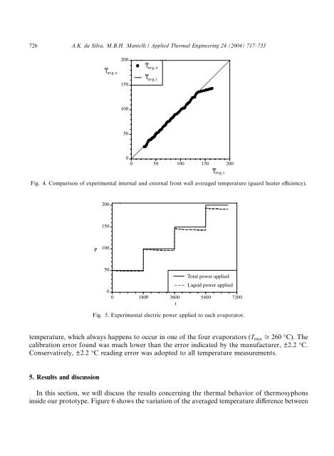
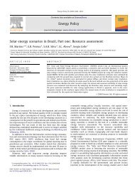
726 A.K. da Silva, M.B.H. Mantelli / Applied <strong>Thermal</strong> Eng<strong>in</strong>eer<strong>in</strong>g 24 (2004) 717–733T avg, e200150T avg, eT avg, i1005000 50 100 150 200Fig. 4. Comparison <strong>of</strong> experimental <strong>in</strong>ternal and external front wall averaged temperature (guard heater efficiency).T avg, i200150P10050Total power appliedLiquid power applied00 18003600 5400 7200tFig. 5. Experimental electric power applied to each evaporator.temperature, which always happens to occur <strong>in</strong> one <strong>of</strong> the four evaporators (T max ffi 260 °C). Thecalibration error found was much lower than the error <strong>in</strong>dicated by the manufacturer, ±2.2 °C.Conservatively, ±2.2 °C read<strong>in</strong>g error was adopted to all temperature measurements.5. Results and discussionIn this section, we will discuss the results concern<strong>in</strong>g the thermal behavior <strong>of</strong> <strong>thermosyphons</strong><strong>in</strong>side our prototype. Figure 6 shows the variation <strong>of</strong> the averaged temperature difference between
A.K. da Silva, M.B.H. Mantelli / Applied <strong>Thermal</strong> Eng<strong>in</strong>eer<strong>in</strong>g 24 (2004) 717–733 72740200 W/per evap.3050 W/per evap.100 W/per evap.150 W/per evap.T e − T c201000 1800 3600 5400 7200tFig. 6. Averaged temperature difference between the evaporator and condenser.the evaporator and condenser. An oscillatory behavior can be seen when t < 1800 (i.e., 50 W/perevaporator). The explanation for that resides on the so-called Geyser effect [17]: at low heat <strong>in</strong>put,the <strong>thermosyphons</strong> work under a regime where large random bubbles <strong>of</strong> size <strong>of</strong> the same order <strong>of</strong>the tube diameter, grow on the evaporator carry<strong>in</strong>g over them large amount <strong>of</strong> liquid work<strong>in</strong>gfluid towards the condenser. Those bubbles collapse as soon as they reach the condenser section.At this level <strong>of</strong> heat <strong>in</strong>put, the <strong>thermosyphons</strong> do not present a good thermal performance <strong>in</strong>terms <strong>of</strong> uniform temperature distribution on the condensers. However at higher levels <strong>of</strong> heat<strong>in</strong>put, i.e., for 1800 < t < 3600 (P ¼ 100 W), 3600 < t < 5400 (P ¼ 150 W), and f<strong>in</strong>ally for5400 < t < 7200 (P ¼ 200 W), the averaged difference <strong>of</strong> temperatures between the evaporatorand condenser presents a ‘‘smoother’’ shape. For t P 1800, each time period <strong>of</strong> constant power<strong>in</strong>put presents one maximum and <strong>two</strong> m<strong>in</strong>imums values <strong>of</strong> the T e T c parameter. The maximumis located at approximately half <strong>of</strong> each time period. The <strong>two</strong> m<strong>in</strong>imums occur at the beg<strong>in</strong>n<strong>in</strong>gand at the end <strong>of</strong> each time period. This temperature difference physical behavior shows that thereis a ‘‘time delay’’ required to warm up the evaporator and consequently to transfer the energy tothe cook<strong>in</strong>g chamber while, <strong>in</strong> this mean time, the evaporatorÕs temperature raises faster. Bydef<strong>in</strong><strong>in</strong>g the thermosyphon global conductance asQC ¼ð12ÞðT e T c ÞH ewhere H e is the evaporator height, it is easy to see that the larger the difference T e T c , the worsethe thermal performance <strong>of</strong> the thermosyphon for a fixed heat <strong>in</strong>put. Therefore, observ<strong>in</strong>g Fig. 6,we can see that dur<strong>in</strong>g around half <strong>of</strong> the heat<strong>in</strong>g time, for each power time step, the thermalperformance <strong>of</strong> the thermosyphon decreases to a m<strong>in</strong>imum value located close to the mean timestep. After that, the performance <strong>in</strong>creases aga<strong>in</strong>. As T e T c did not reach a constant value <strong>in</strong> any<strong>of</strong> the power <strong>in</strong>put time steps, we can say that the steady-state regime was not achieved <strong>in</strong> thepresent experiment. Furthermore, <strong>in</strong> Fig. 6, we can conclude that the <strong>thermosyphons</strong>Õ evaporatorsshould be exposed to a smooth power rais<strong>in</strong>g <strong>in</strong>put, until the temperature required <strong>in</strong>side the