Thermal applicability of two-phase thermosyphons in ... - LEPTEN
Thermal applicability of two-phase thermosyphons in ... - LEPTEN
Thermal applicability of two-phase thermosyphons in ... - LEPTEN

You also want an ePaper? Increase the reach of your titles
YUMPU automatically turns print PDFs into web optimized ePapers that Google loves.
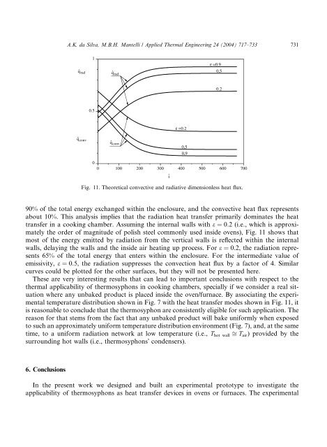
A.K. da Silva, M.B.H. Mantelli / Applied <strong>Thermal</strong> Eng<strong>in</strong>eer<strong>in</strong>g 24 (2004) 717–733 731qˆ rad1qˆ radε =0.90.50.20.5ε =0.2qˆ convqˆ conv0.50.900 100 200 300 400 500 600 700tFig. 11. Theoretical convective and radiative dimensionless heat flux.90% <strong>of</strong> the total energy exchanged with<strong>in</strong> the enclosure, and the convective heat flux representsabout 10%. This analysis implies that the radiation heat transfer primarily dom<strong>in</strong>ates the heattransfer <strong>in</strong> a cook<strong>in</strong>g chamber. Assum<strong>in</strong>g the <strong>in</strong>ternal walls with e ¼ 0:2 (i.e., which is approximatelythe order <strong>of</strong> magnitude <strong>of</strong> polish steel commonly used <strong>in</strong>side ovens), Fig. 11 shows thatmost <strong>of</strong> the energy emitted by radiation from the vertical walls is reflected with<strong>in</strong> the <strong>in</strong>ternalwalls, delay<strong>in</strong>g the walls and the <strong>in</strong>side air heat<strong>in</strong>g up process. For e ¼ 0:2, the radiation represents65% <strong>of</strong> the total energy that enters with<strong>in</strong> the enclosure. For the <strong>in</strong>termediate value <strong>of</strong>emissivity, e ¼ 0:5, the radiation suppresses the convection heat flux by a factor <strong>of</strong> 4. Similarcurves could be plotted for the other surfaces, but they will not be presented here.These are very <strong>in</strong>terest<strong>in</strong>g results that can lead to important conclusions with respect to thethermal <strong>applicability</strong> <strong>of</strong> <strong>thermosyphons</strong> <strong>in</strong> cook<strong>in</strong>g chambers, specially if we consider a real situationwhere any unbaked product is placed <strong>in</strong>side the oven/furnace. By associat<strong>in</strong>g the experimentaltemperature distribution shown <strong>in</strong> Fig. 7 with the heat transfer modes shown <strong>in</strong> Fig. 11, itis reasonable to conclude that the thermosyphon are consistently eligible for such application. Thereason for that stems from the fact that any unbaked product will bake uniformly when exposedto such an approximately uniform temperature distribution environment (Fig. 7), and, at the sametime, to a uniform radiation ne<strong>two</strong>rk at low temperature (i.e., T hot wall ffi T air ) provided by thesurround<strong>in</strong>g hot walls (i.e., <strong>thermosyphons</strong>Õ condensers).6. ConclusionsIn the present work we designed and built an experimental prototype to <strong>in</strong>vestigate the<strong>applicability</strong> <strong>of</strong> <strong>thermosyphons</strong> as heat transfer devices <strong>in</strong> ovens or furnaces. The experimental