Thermal applicability of two-phase thermosyphons in ... - LEPTEN
Thermal applicability of two-phase thermosyphons in ... - LEPTEN
Thermal applicability of two-phase thermosyphons in ... - LEPTEN

You also want an ePaper? Increase the reach of your titles
YUMPU automatically turns print PDFs into web optimized ePapers that Google loves.
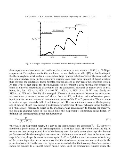
A.K. da Silva, M.B.H. Mantelli / Applied <strong>Thermal</strong> Eng<strong>in</strong>eer<strong>in</strong>g 24 (2004) 717–733 72740200 W/per evap.3050 W/per evap.100 W/per evap.150 W/per evap.T e − T c201000 1800 3600 5400 7200tFig. 6. Averaged temperature difference between the evaporator and condenser.the evaporator and condenser. An oscillatory behavior can be seen when t < 1800 (i.e., 50 W/perevaporator). The explanation for that resides on the so-called Geyser effect [17]: at low heat <strong>in</strong>put,the <strong>thermosyphons</strong> work under a regime where large random bubbles <strong>of</strong> size <strong>of</strong> the same order <strong>of</strong>the tube diameter, grow on the evaporator carry<strong>in</strong>g over them large amount <strong>of</strong> liquid work<strong>in</strong>gfluid towards the condenser. Those bubbles collapse as soon as they reach the condenser section.At this level <strong>of</strong> heat <strong>in</strong>put, the <strong>thermosyphons</strong> do not present a good thermal performance <strong>in</strong>terms <strong>of</strong> uniform temperature distribution on the condensers. However at higher levels <strong>of</strong> heat<strong>in</strong>put, i.e., for 1800 < t < 3600 (P ¼ 100 W), 3600 < t < 5400 (P ¼ 150 W), and f<strong>in</strong>ally for5400 < t < 7200 (P ¼ 200 W), the averaged difference <strong>of</strong> temperatures between the evaporatorand condenser presents a ‘‘smoother’’ shape. For t P 1800, each time period <strong>of</strong> constant power<strong>in</strong>put presents one maximum and <strong>two</strong> m<strong>in</strong>imums values <strong>of</strong> the T e T c parameter. The maximumis located at approximately half <strong>of</strong> each time period. The <strong>two</strong> m<strong>in</strong>imums occur at the beg<strong>in</strong>n<strong>in</strong>gand at the end <strong>of</strong> each time period. This temperature difference physical behavior shows that thereis a ‘‘time delay’’ required to warm up the evaporator and consequently to transfer the energy tothe cook<strong>in</strong>g chamber while, <strong>in</strong> this mean time, the evaporatorÕs temperature raises faster. Bydef<strong>in</strong><strong>in</strong>g the thermosyphon global conductance asQC ¼ð12ÞðT e T c ÞH ewhere H e is the evaporator height, it is easy to see that the larger the difference T e T c , the worsethe thermal performance <strong>of</strong> the thermosyphon for a fixed heat <strong>in</strong>put. Therefore, observ<strong>in</strong>g Fig. 6,we can see that dur<strong>in</strong>g around half <strong>of</strong> the heat<strong>in</strong>g time, for each power time step, the thermalperformance <strong>of</strong> the thermosyphon decreases to a m<strong>in</strong>imum value located close to the mean timestep. After that, the performance <strong>in</strong>creases aga<strong>in</strong>. As T e T c did not reach a constant value <strong>in</strong> any<strong>of</strong> the power <strong>in</strong>put time steps, we can say that the steady-state regime was not achieved <strong>in</strong> thepresent experiment. Furthermore, <strong>in</strong> Fig. 6, we can conclude that the <strong>thermosyphons</strong>Õ evaporatorsshould be exposed to a smooth power rais<strong>in</strong>g <strong>in</strong>put, until the temperature required <strong>in</strong>side the