Thermal applicability of two-phase thermosyphons in ... - LEPTEN
Thermal applicability of two-phase thermosyphons in ... - LEPTEN
Thermal applicability of two-phase thermosyphons in ... - LEPTEN

Create successful ePaper yourself
Turn your PDF publications into a flip-book with our unique Google optimized e-Paper software.
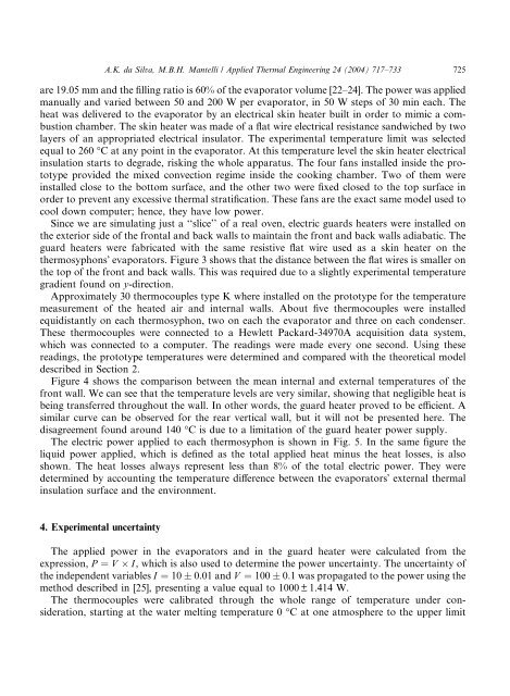
A.K. da Silva, M.B.H. Mantelli / Applied <strong>Thermal</strong> Eng<strong>in</strong>eer<strong>in</strong>g 24 (2004) 717–733 725are 19.05 mm and the fill<strong>in</strong>g ratio is 60% <strong>of</strong> the evaporator volume [22–24]. The power was appliedmanually and varied between 50 and 200 W per evaporator, <strong>in</strong> 50 W steps <strong>of</strong> 30 m<strong>in</strong> each. Theheat was delivered to the evaporator by an electrical sk<strong>in</strong> heater built <strong>in</strong> order to mimic a combustionchamber. The sk<strong>in</strong> heater was made <strong>of</strong> a flat wire electrical resistance sandwiched by <strong>two</strong>layers <strong>of</strong> an appropriated electrical <strong>in</strong>sulator. The experimental temperature limit was selectedequal to 260 °C at any po<strong>in</strong>t <strong>in</strong> the evaporator. At this temperature level the sk<strong>in</strong> heater electrical<strong>in</strong>sulation starts to degrade, risk<strong>in</strong>g the whole apparatus. The four fans <strong>in</strong>stalled <strong>in</strong>side the prototypeprovided the mixed convection regime <strong>in</strong>side the cook<strong>in</strong>g chamber. Two <strong>of</strong> them were<strong>in</strong>stalled close to the bottom surface, and the other <strong>two</strong> were fixed closed to the top surface <strong>in</strong>order to prevent any excessive thermal stratification. These fans are the exact same model used tocool down computer; hence, they have low power.S<strong>in</strong>ce we are simulat<strong>in</strong>g just a ‘‘slice’’ <strong>of</strong> a real oven, electric guards heaters were <strong>in</strong>stalled onthe exterior side <strong>of</strong> the frontal and back walls to ma<strong>in</strong>ta<strong>in</strong> the front and back walls adiabatic. Theguard heaters were fabricated with the same resistive flat wire used as a sk<strong>in</strong> heater on the<strong>thermosyphons</strong>Õ evaporators. Figure 3 shows that the distance between the flat wires is smaller onthe top <strong>of</strong> the front and back walls. This was required due to a slightly experimental temperaturegradient found on y-direction.Approximately 30 thermocouples type K where <strong>in</strong>stalled on the prototype for the temperaturemeasurement <strong>of</strong> the heated air and <strong>in</strong>ternal walls. About five thermocouples were <strong>in</strong>stalledequidistantly on each thermosyphon, <strong>two</strong> on each the evaporator and three on each condenser.These thermocouples were connected to a Hewlett Packard-34970A acquisition data system,which was connected to a computer. The read<strong>in</strong>gs were made every one second. Us<strong>in</strong>g theseread<strong>in</strong>gs, the prototype temperatures were determ<strong>in</strong>ed and compared with the theoretical modeldescribed <strong>in</strong> Section 2.Figure 4 shows the comparison between the mean <strong>in</strong>ternal and external temperatures <strong>of</strong> thefront wall. We can see that the temperature levels are very similar, show<strong>in</strong>g that negligible heat isbe<strong>in</strong>g transferred throughout the wall. In other words, the guard heater proved to be efficient. Asimilar curve can be observed for the rear vertical wall, but it will not be presented here. Thedisagreement found around 140 °C is due to a limitation <strong>of</strong> the guard heater power supply.The electric power applied to each thermosyphon is shown <strong>in</strong> Fig. 5. In the same figure theliquid power applied, which is def<strong>in</strong>ed as the total applied heat m<strong>in</strong>us the heat losses, is alsoshown. The heat losses always represent less than 8% <strong>of</strong> the total electric power. They weredeterm<strong>in</strong>ed by account<strong>in</strong>g the temperature difference between the evaporatorsÕ external thermal<strong>in</strong>sulation surface and the environment.4. Experimental uncerta<strong>in</strong>tyThe applied power <strong>in</strong> the evaporators and <strong>in</strong> the guard heater were calculated from theexpression, P ¼ V I, which is also used to determ<strong>in</strong>e the power uncerta<strong>in</strong>ty. The uncerta<strong>in</strong>ty <strong>of</strong>the <strong>in</strong>dependent variables I ¼ 10 0:01 and V ¼ 100 0:1 was propagated to the power us<strong>in</strong>g themethod described <strong>in</strong> [25], present<strong>in</strong>g a value equal to 1000 ± 1.414 W.The thermocouples were calibrated through the whole range <strong>of</strong> temperature under consideration,start<strong>in</strong>g at the water melt<strong>in</strong>g temperature 0 °C at one atmosphere to the upper limit