MOLDED-CASE CIRCUIT BREAKERS & EARTH ... - Piti Group
MOLDED-CASE CIRCUIT BREAKERS & EARTH ... - Piti Group
MOLDED-CASE CIRCUIT BREAKERS & EARTH ... - Piti Group

Create successful ePaper yourself
Turn your PDF publications into a flip-book with our unique Google optimized e-Paper software.
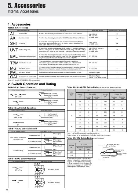
5. Accessories<br />
Internal Accessories<br />
1. Accessories<br />
Table 5-1: Accessories<br />
Internal accessories Function Applicable models Cassette-type of accessories<br />
AL Alarm switch A switch that electrically indicates the trip status of the circuit breaker. NF-C·S·H·U,<br />
●<br />
Auxiliary switch A switch that electrically indicates the ON-OFF status of the circuit breaker.<br />
NV-C·S·H·U<br />
and MB series<br />
●<br />
AX<br />
SHT<br />
UVT<br />
EAL<br />
TBM<br />
MG<br />
PAL<br />
OAL<br />
OFF or ON<br />
Trip<br />
OFF or Trip<br />
ON<br />
Shunt trip<br />
A<br />
Note: (1) Models NV250-SEW/HEW are excluded.<br />
Over current, short circuit<br />
trip or on or off<br />
Ground-fault trip<br />
Undervoltage trip<br />
A<br />
Earth-leakage alarm switch<br />
A<br />
Test button module<br />
This<br />
Insulation switch<br />
The<br />
Pre-alarm module<br />
Overcurrent trip alarm switch<br />
Indicates<br />
2. Switch Operation and Rating<br />
Table 5-2: AL Switch Operation<br />
Circuit breaker status<br />
Table 5-3: AX Switch Operation<br />
Circuit breaker status<br />
Table 5-4: EAL Switch Operation<br />
Circuit breaker status<br />
250A frame or less<br />
400A frame or more<br />
250A frame or less<br />
400A frame or more<br />
Table 5-5: MG Switch Operation<br />
Circuit breaker status<br />
device that electrically trips the circuit breaker from a remote distance.<br />
Permissible working voltages are 70 to 110% of the AC rated voltage or<br />
70 to 125% of the DC rated voltage.<br />
device that automatically trips the circuit breaker if the voltage is lowered.<br />
Working voltages are 70 to 35% of the UVT rated voltage. When the voltage<br />
recovers to 85% or higher, you can reset the device and put into operation.<br />
switch that electrically indicates the trip status of the earth leakage circuit<br />
breaker caused by a ground fault. If 250AF and less, This switch is available<br />
only for models with the vertical lead-wire terminal unit (SLT).<br />
module allows you a remote testing by applying a voltage.<br />
An external sequence common to SHT can be used. (The standard<br />
configuration requires the vertical lead-wire terminal unit (SLT).)<br />
incorporation of this switch enables the measurement of insulation resistance<br />
between the terminals of the load with the circuit breaker being turned OFF.<br />
that the load current exceeds the pre-alarm setting current.<br />
Indicates that the breaker has been tripped by overcurrent or short-circuit current.<br />
AL switch contact<br />
AX switch contact<br />
EAL switch contact<br />
MG switch status<br />
98/ALa (open)<br />
96/ALb (closed)<br />
95/ALc<br />
98/ALa (closed)<br />
96/ALb (open)<br />
95/ALc<br />
14/AXa (open)<br />
12/AXb (closed)<br />
11/AXc<br />
14/AXa (closed)<br />
12/AXb (open)<br />
11/AXc<br />
EALa (open)<br />
EALc<br />
EALa (open)<br />
EALb (closed)<br />
EALc<br />
EALa (closed)<br />
EALc<br />
EALa (closed)<br />
EALb (open)<br />
EALc<br />
Table 5-6: AL·AX·EAL Switch Rating (In case of EAL, 400AF and more)<br />
Switch<br />
type<br />
S<br />
V<br />
*1<br />
X<br />
Note: *1. When DC use polarity must be considered.<br />
Please contact us for applications in the field of smaller current values.<br />
Table 5-7: EAL Switch Rating (250AF and less)<br />
Voltage<br />
(V)<br />
Voltage<br />
(V)<br />
Resistive<br />
load<br />
AC<br />
Resistive<br />
load<br />
Inductive<br />
load<br />
A control power supply (compatible to<br />
100 and 200V AC) is required; see the<br />
diagram on the right showing its wiring.<br />
(The permissible range of voltage of the<br />
control power supply is 80 to 242V AC,<br />
and the power requirement is 10VA.)<br />
NF-C·S·H·U<br />
and MB series<br />
NF-C·S·H·U, (Note 1)<br />
NV-C·S·H·U<br />
and MB series<br />
NV-C·S·H·U –<br />
NV-C·S·H·U –<br />
NV-C·S·H·U –<br />
Electronic Types –<br />
Electronic Types<br />
(SGW, HGW, RGW, UGW)<br />
Current (A)<br />
Inductive<br />
load<br />
Voltage<br />
(V)<br />
DC<br />
Resistive<br />
load<br />
–<br />
Current (A)<br />
Inductive<br />
load<br />
460 – – 250 0.2 0.2<br />
250 3 2 125 0.4 0.4<br />
125 5 3 30 4 3<br />
460<br />
250<br />
125<br />
460<br />
250<br />
125<br />
AC<br />
Current A<br />
5<br />
10<br />
10<br />
5<br />
10<br />
10<br />
200 3 2<br />
100 3 2<br />
2<br />
10<br />
10<br />
2.5<br />
10<br />
10<br />
250<br />
125<br />
30<br />
250<br />
125<br />
30<br />
0.3<br />
0.6<br />
10<br />
5<br />
10<br />
10<br />
●<br />
●<br />
0.3<br />
0.6<br />
Vertical lead-wire<br />
terminal unit<br />
EALa<br />
Indicator lamp<br />
(example)<br />
P2 Control power<br />
supply<br />
P1(EALc)<br />
6<br />
3<br />
6<br />
10<br />
OFF or Trip<br />
MG switch (open)<br />
ON<br />
MG switch (closed)<br />
43