14.7 - Fault and Protection Schedule - EDF Hinkley Point
14.7 - Fault and Protection Schedule - EDF Hinkley Point
14.7 - Fault and Protection Schedule - EDF Hinkley Point

Create successful ePaper yourself
Turn your PDF publications into a flip-book with our unique Google optimized e-Paper software.
PRE-CONSTRUCTION SAFETY REPORT<br />
CHAPTER 14: DESIGN BASIS ANALYSIS<br />
SUB-CHAPTER : <strong>14.7</strong><br />
PAGE : 15 / 48<br />
Document ID.No.<br />
UKEPR-0002-149 Issue 02<br />
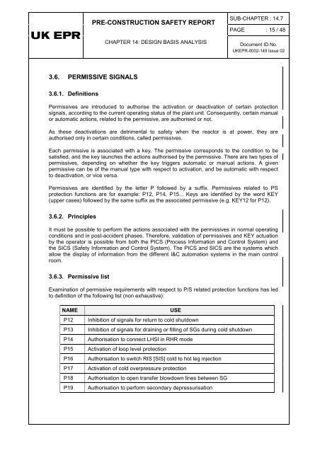
3.6. PERMISSIVE SIGNALS<br />
3.6.1. Definitions<br />
Permissives are introduced to authorise the activation or deactivation of certain protection<br />
signals, according to the current operating status of the plant unit. Consequently, certain manual<br />
or automatic actions, related to the permissive, are authorised or not.<br />
As these deactivations are detrimental to safety when the reactor is at power, they are<br />
authorised only in certain conditions, called permissives.<br />
Each permissive is associated with a key. The permissive corresponds to the condition to be<br />
satisfied, <strong>and</strong> the key launches the actions authorised by the permissive. There are two types of<br />
permissives, depending on whether the key triggers automatic or manual actions. A given<br />
permissive can be of the manual type with respect to activation, <strong>and</strong> be automatic with respect<br />
to deactivation, or vice versa.<br />
Permissives are identified by the letter P followed by a suffix. Permissives related to PS<br />
protection functions are for example: P12, P14, P15... Keys are identified by the word KEY<br />
(upper cases) followed by the same suffix as the associated permissive (e.g. KEY12 for P12).<br />
3.6.2. Principles<br />
It must be possible to perform the actions associated with the permissives in normal operating<br />
conditions <strong>and</strong> in post-accident phases. Therefore, validation of permissives <strong>and</strong> KEY actuation<br />
by the operator is possible from both the PICS (Process Information <strong>and</strong> Control System) <strong>and</strong><br />
the SICS (Safety Information <strong>and</strong> Control System). The PICS <strong>and</strong> SICS are the systems which<br />
allow the display of information from the different I&C automation systems in the main control<br />
room.<br />
3.6.3. Permissive list<br />
Examination of permissive requirements with respect to P/S related protection functions has led<br />
to definition of the following list (non exhaustive):<br />
NAME<br />
P12<br />
P13<br />
P14<br />
P15<br />
P16<br />
P17<br />
P18<br />
P19<br />
USE<br />
Inhibition of signals for return to cold shutdown<br />
Inhibition of signals for draining or filling of SGs during cold shutdown<br />
Authorisation to connect LHSI in RHR mode<br />
Activation of loop level protection<br />
Authorisation to switch RIS [SIS] cold to hot leg injection<br />
Activation of cold overpressure protection<br />
Authorisation to open transfer blowdown lines between SG<br />
Authorisation to perform secondary depressurisation


![6.3 - Safety Injection System (RIS [SIS]) - EDF Hinkley Point](https://img.yumpu.com/42739985/1/184x260/63-safety-injection-system-ris-sis-edf-hinkley-point.jpg?quality=85)