14.7 - Fault and Protection Schedule - EDF Hinkley Point
14.7 - Fault and Protection Schedule - EDF Hinkley Point
14.7 - Fault and Protection Schedule - EDF Hinkley Point

You also want an ePaper? Increase the reach of your titles
YUMPU automatically turns print PDFs into web optimized ePapers that Google loves.
PRE-CONSTRUCTION SAFETY REPORT<br />
CHAPTER 14: DESIGN BASIS ANALYSIS<br />
SUB-CHAPTER : <strong>14.7</strong><br />
PAGE : 27 / 48<br />
Document ID.No.<br />
UKEPR-0002-149 Issue 02<br />
Input to classification<br />
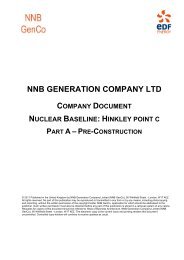
SUB-CHAPTER <strong>14.7</strong> - TABLE 1: FAULT AND PROTECTION SCHEDULE TABLE: FAULTS AT FULL POWER (10/24)<br />
SAFETY FUNCTION<br />
MAIN LINE<br />
DIVERSE LINE<br />
<strong>Fault</strong><br />
description<br />
Category<br />
References<br />
Frequency<br />
PCSR<br />
Ref.<br />
Main Safety<br />
Function<br />
Transient phases<br />
Cont.<br />
state<br />
Safe<br />
state<br />
Final<br />
state<br />
Plant Level Safety Function<br />
Based on EPR process <strong>and</strong><br />
international practice for<br />
PWR<br />
Safety Cat.<br />
Lower Level Safety Function<br />
Combination of the Plant Level<br />
Safety Function <strong>and</strong> the<br />
conditions of operations<br />
(normal, incident, accident)<br />
Safety Functional Groups<br />
Item<br />
Safety<br />
class<br />
System<br />
Req.<br />
C&I<br />
platform<br />
Lower Level Safety Function<br />
Combination of the Plant Level<br />
Safety Function <strong>and</strong> the<br />
conditions of operations<br />
(normal, incident, accident)<br />
Safety Functional Groups<br />
Item<br />
Safety<br />
class<br />
Syst<br />
Req.<br />
Supporting study<br />
Comments<br />
Decrease in RCS water inventory<br />
Reactivity<br />
Control<br />
x<br />
x<br />
x<br />
Shutdown <strong>and</strong> maintain core<br />
sub-criticality<br />
Prevention of uncontrolled<br />
positive reactivity insertion<br />
into the core<br />
B<br />
B<br />
Negative reactivity fast insertion<br />
RCS overcooling protection<br />
Reactor trip - auto<br />
Actuation<br />
PZR P<br />
HL P<br />
Front. Syst. CRDM<br />
Turbine Trip<br />
Actuation RT checkback<br />
Front. Syst.<br />
Turbine admission<br />
valves<br />
Full load MFW isolation (4SG)<br />
Actuation RT checkback<br />
Front. Syst.<br />
Full load MFW<br />
isolation valves<br />
Class 1<br />
Class 1<br />
Class 1<br />
F1A<br />
F1A<br />
F1A<br />
PS<br />
PS<br />
PS<br />
x<br />
x<br />
x<br />
Maintain sufficient Reactor<br />
Coolant System water<br />
inventory for core cooling<br />
B<br />
B<br />
Water injection into the RCS<br />
Prevention of RCS drainage<br />
through auxiliary lines<br />
SG Pressure Control - Cooling<br />
Actuation Manual<br />
Front. Syst. MSRT<br />
MHSI injection - Auto<br />
Actuation SIS signal [PZR P ]<br />
Front. Syst. MHSI<br />
Isolation of CVCS letdown line<br />
(RCS isolation SI sequence)<br />
Actuation SIS signal [PZR P ]<br />
Front. Syst.<br />
CVCS letdown valve<br />
Class 2<br />
Class 1<br />
Class 1<br />
F1B<br />
F1A<br />
F1A<br />
SAS<br />
PS<br />
PS<br />
LOCA up to 20<br />
cm 2 without<br />
LHSI (at power)<br />
RRC-A - 16.1.3.8<br />
Heat removal<br />
Other<br />
Confinement<br />
x<br />
x<br />
x<br />
x<br />
x<br />
x<br />
x<br />
x<br />
x<br />
Transfer heat from the reactor<br />
coolant to the ultimate heat<br />
sink<br />
Prevent the failure or limit the<br />
consequences of failure of a<br />
structure, system or<br />
component whose failure<br />
could cause the impairment of<br />
a safety function<br />
Limit the release of<br />
radioactive material from the<br />
reactor containment<br />
B<br />
B<br />
B<br />
Heat removal by Steam<br />
Generators - Emergency<br />
shutdown mode<br />
Heat removal in shutdown<br />
mode by Residual Heat<br />
Removal system (RHRS)<br />
Heat removal by Steam<br />
Generators - Emergency<br />
shutdown mode<br />
SG Pressure Control - Cooling<br />
Actuation<br />
Front. Syst.<br />
Activ. & Elec<br />
Front. Syst.<br />
SG P<br />
MSRT<br />
LHSI switch to RHR mode (1 train)<br />
Manual<br />
RHRS<br />
IRWST cooling<br />
Actuation SIS signal [PZR P]<br />
Front. Syst. RHRS<br />
Accumulators injection<br />
Actuation Passive<br />
Front. Syst. Accumulators<br />
LHSI injection in CL<br />
Actuation SIS signal [PZR P]<br />
Front. Syst. LHSI<br />
IRWST borated water storage,<br />
collect, filtration<br />
Actuation Passive<br />
Front. Syst. IRWST systems<br />
EFW actuation (1 train) + SG<br />
Actuation<br />
SG L<br />
Front. Syst.<br />
EFWS injection lines<br />
& storages<br />
SG Pressure Control -<br />
Overpressure protection<br />
Actuation<br />
SG P<br />
Essential component protection Front. Syst. MSRT<br />
RCP stop - Auto<br />
Actuation<br />
DP over RCP + SIS<br />
signal<br />
Front. Syst. RCP<br />
Containment isolation stage 1 /<br />
RCPB isolation<br />
Containment building isolation Actuation SIS signal [PZR P ]<br />
Front. Syst.<br />
Containment<br />
isolation valves<br />
Class 1 F1A PS<br />
Class 2 F1B SAS<br />
Class 1 F1A PS<br />
Class 1 F1A PS<br />
Class 2 F1B PS<br />
Class 1 F1A PS<br />
Class 1<br />
Class 1<br />
Class 1<br />
F1A PS<br />
F1A PS<br />
F1A PS<br />
Class 1 F1A PS<br />
N/A - diversity is applied to frequent initiating event above 10-3/r.y<br />
In such case, due to the loss of LHSI, the<br />
cooling is made by the CHRS [EVU] with a<br />
cooling of the IRWST. The MHSI are<br />
switched to large min flow lines. The cooling<br />
is then ensured by a circulation between the<br />
cooled IRWST, the MHSI injection <strong>and</strong> the<br />
break.


![6.3 - Safety Injection System (RIS [SIS]) - EDF Hinkley Point](https://img.yumpu.com/42739985/1/184x260/63-safety-injection-system-ris-sis-edf-hinkley-point.jpg?quality=85)