02-a Wet etching - Caltech Micromachining Laboratory
02-a Wet etching - Caltech Micromachining Laboratory
02-a Wet etching - Caltech Micromachining Laboratory

Create successful ePaper yourself
Turn your PDF publications into a flip-book with our unique Google optimized e-Paper software.
l eaN ;,..~;;1.,: -.~~.~<br />
~ Vol. ~, o.~. '.:J~-~."~:;~ ..'.,~...';,~.:,."'-""Q~~~IA --".~~-,:",;',::£~ CAL.'. "';i~~~::'" ETCHIN~ DF.SILICO~ ,'.' c-~', ~t':: ;;:'~..:~~""'::.r.. ~~. '- ,~~j~':';""~:i-.7 "i;--i,.:..",l9.Qb,;:---~.:.,<br />
.~.,.,~" ..'~<br />
high H<br />
NOf/-CATALYZED RATES faces<br />
-CATALYZED RATES 80<br />
Hz (~46%)<br />
HF (59<br />
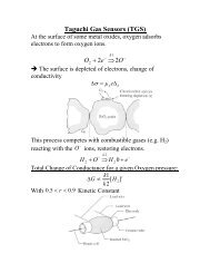
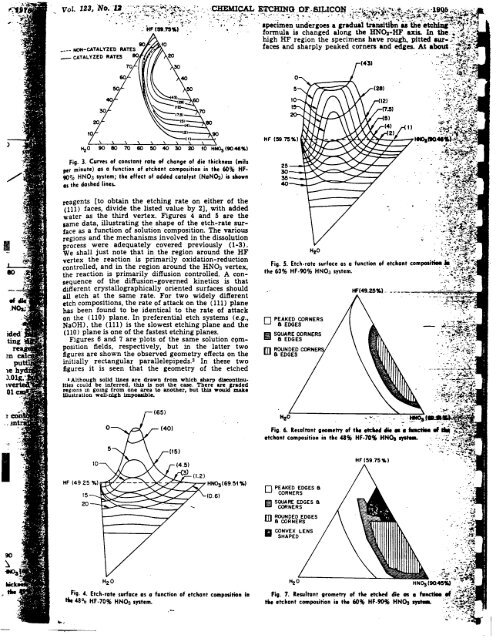
Fig. 3. Curyes of constont rate of change of die thickness (mils<br />
per minute) as 0 function of etchant composition in the 60% HF. ~<br />
9O~o HNO3 system; the effect of added catalyst (NaN~) is shown 35<br />
os the dashed lines. 40<br />
reagents [to obtain the <strong>etching</strong> rate on either of the<br />
(Ill) faces, divide the listed value by 2], with added .<br />
water as the third vertex. Figures 4 and 5 are the<br />
same data, illustrating the shape of the etch-rate surface<br />
as a function of solution composition. The various<br />
I regions and the mechanisms involved in the dissolution<br />
process were adequately covered previously (1-3).<br />
..We shall just note that in the region around the HF<br />
vertex the reaction is primarily oxidation-reduction F' 5<br />
controlled, and in the region around the HNO3 vertex, Ig. .<br />
the reaction is primarily diffusion controlled. A con- the 60%<br />
sequence of the diffusion-governed kinetics is that<br />
different all etch at crystallographically the same rate. For oriented two widely surfaces different' should - .<br />
etch compositions, the rate of attack on the (Ill) plane<br />
has been found to be identical to the rate of attack<br />
on the (110) plane. In preferential etch systems (e.g., 0 PEAKED CORNERS<br />
NaOH), the (Ill) is the slowest <strong>etching</strong> plane and the 6 EDGES<br />
(110) plane is one of the fastest <strong>etching</strong> planes. m SQUARE CORNERS<br />
Figures 6 and 7 are plots of the same solution com- ~ 6 EDGES<br />
position fields, respectively, but in the latter two<br />
m ROUNDED ~N<br />
figures are shown the observed geometry effects on the 6 EDGES<br />
initially rectangular parallelepipeds.3 In these two<br />
figures it is seen that the geometry of the etched<br />
I Although solid tines are drawn from which sharp d!8COntinu.<br />
Itles could be inferred, this Is not the C&.se. Tbere are ended<br />
regIons in going from one area to another, but this would make<br />
Wustration well-n1ib imposaible.<br />
~,<br />
..etchant<br />
~<br />
c ,I<br />
co HF (492 H~(6951%)<br />
Hz<br />
Fig. 6.<br />
0 PEAKED EDGES 6<br />
15 (0.6) CORNERS<br />
20 ~ SQUAREDGES 8<br />
EO! CORNERS<br />
m ROUNDED EDGES<br />
6 CORNERS<br />
-CONVEX<br />
-SHAPED<br />
LENS<br />
H2O<br />
,. Fig. 4. Etch-rate surface as a function of etchant composition in Fig. 7<br />
~ 48% HF-70% HNOa system. the etch<br />
~ --~,:.- ;"~-