ADDENDUM NO. 2 CITY OF SAN ANTONIO CAPITAL ...
ADDENDUM NO. 2 CITY OF SAN ANTONIO CAPITAL ...
ADDENDUM NO. 2 CITY OF SAN ANTONIO CAPITAL ...
Create successful ePaper yourself
Turn your PDF publications into a flip-book with our unique Google optimized e-Paper software.
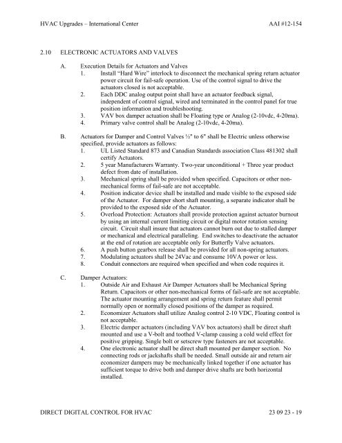
HVAC Upgrades – International Center AAI #12-154<br />
2.10 ELECTRONIC ACTUATORS AND VALVES<br />
A. Execution Details for Actuators and Valves<br />
1. Install “Hard Wire” interlock to disconnect the mechanical spring return actuator<br />
power circuit for fail-safe operation. Use of the control signal to drive the<br />
actuators closed is not acceptable.<br />
2. Each DDC analog output point shall have an actuator feedback signal,<br />
independent of control signal, wired and terminated in the control panel for true<br />
position information and troubleshooting.<br />
3. VAV box damper actuation shall be Floating type or Analog (2-10vdc, 4-20ma).<br />
4. Primary valve control shall be Analog (2-10vdc, 4-20ma).<br />
B. Actuators for Damper and Control Valves ½" to 6" shall be Electric unless otherwise<br />
specified, provide actuators as follows:<br />
1. UL Listed Standard 873 and Canadian Standards association Class 481302 shall<br />
certify Actuators.<br />
2. 5 year Manufacturers Warranty. Two-year unconditional + Three year product<br />
defect from date of installation.<br />
3. Mechanical spring shall be provided when specified. Capacitors or other nonmechanical<br />
forms of fail-safe are not acceptable.<br />
4. Position indicator device shall be installed and made visible to the exposed side<br />
of the Actuator. For damper short shaft mounting, a separate indicator shall be<br />
provided to the exposed side of the Actuator.<br />
5. Overload Protection: Actuators shall provide protection against actuator burnout<br />
by using an internal current limiting circuit or digital motor rotation sensing<br />
circuit. Circuit shall insure that actuators cannot burn out due to stalled damper<br />
or mechanical and electrical paralleling. End switches to deactivate the actuator<br />
at the end of rotation are acceptable only for Butterfly Valve actuators.<br />
6. A push button gearbox release shall be provided for all non-spring actuators.<br />
7. Modulating actuators shall be 24Vac and consume 10VA power or less.<br />
8. Conduit connectors are required when specified and when code requires it.<br />
C. Damper Actuators:<br />
1. Outside Air and Exhaust Air Damper Actuators shall be Mechanical Spring<br />
Return. Capacitors or other non-mechanical forms of fail-safe are not acceptable.<br />
The actuator mounting arrangement and spring return feature shall permit<br />
normally open or normally closed positions of the damper as required.<br />
2. Economizer Actuators shall utilize Analog control 2-10 VDC, Floating control is<br />
not acceptable.<br />
3. Electric damper actuators (including VAV box actuators) shall be direct shaft<br />
mounted and use a V-bolt and toothed V-clamp causing a cold weld effect for<br />
positive gripping. Single bolt or setscrew type fasteners are not acceptable.<br />
4. One electronic actuator shall be direct shaft mounted per damper section. No<br />
connecting rods or jackshafts shall be needed. Small outside air and return air<br />
economizer dampers may be mechanically linked together if one actuator has<br />
sufficient torque to drive both and damper drive shafts are both horizontal<br />
installed.<br />
DIRECT DIGITAL CONTROL FOR HVAC 23 09 23 - 19


