DALI manual - Tridonic
DALI manual - Tridonic
DALI manual - Tridonic

Create successful ePaper yourself
Turn your PDF publications into a flip-book with our unique Google optimized e-Paper software.
.<br />
c<br />
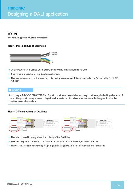
Designing a <strong>DALI</strong> application<br />
Wiring<br />
The following points must be considered:<br />
Figure: Typical texture of used wires<br />
<strong>DALI</strong> systems are installed using conventional wiring material for line voltage.<br />
Two wires are needed for the <strong>DALI</strong> control circuit.<br />
The line voltage and bus line may be routed in the same cable. This corresponds to a 5-core cable (L, N, PE,<br />
DA, DA)<br />
I NOTICE<br />
According to DIN VDE 0100/T520/Part 6, main circuits and associated auxiliary circuits may be laid together even if<br />
the auxiliary circuits carry a lower voltage than the main circuits. Make sure to use cable designed to take the<br />
maximum operating voltage.<br />
Figure: Different polarity of <strong>DALI</strong> lines<br />
There is no need to worry about the polarity of the <strong>DALI</strong> line.<br />
The <strong>DALI</strong> signal is not SELV. The installation instructions for low voltage therefore apply<br />
There are no special network topology requirements (star and mixed networking are permitted)<br />
<strong>DALI</strong> Manual | 08-2013 | en<br />
61 / 93