INCH-POUND MIL-PRF-13830B 9 January 1997 SUPERSEDING ...
INCH-POUND MIL-PRF-13830B 9 January 1997 SUPERSEDING ...
INCH-POUND MIL-PRF-13830B 9 January 1997 SUPERSEDING ...

Create successful ePaper yourself
Turn your PDF publications into a flip-book with our unique Google optimized e-Paper software.
<strong>MIL</strong>-<strong>PRF</strong>-<strong>13830B</strong><br />
3.2.3 Bonding system. Bonding system for glass to metal bonding shall be<br />
in accordance with Appendix D.<br />
3.2.4 Sealing compound. Sealing compound shall be in accordance with<br />
Appendix E.<br />
3.2.5 Reflection reducing film. Reflection reducing film required for coating<br />
of specified optical surfaces shall be in accordance with Appendix C.<br />
3.2.5.1 Reflecting surfaces . Aluminized reflecting surfaces shall be in<br />
accordance with Appendix B.<br />
3.3 Mechanical dimensions. Optical elements shall conform to the<br />
mechanical dimensions and optical data specified on the drawings or in the<br />
contract.<br />
3.3.1 Rim edges. Rim edges of all optical parts shall have a chamfer of<br />
0.020 inch - 0.010 at 45 degrees ± 15 degrees as measured along the face width<br />
unless otherwise specified by the drawing. Edges meeting at angles of 135<br />
degrees and larger need not be beveled unless specified by the drawings.<br />
3.4 Finish and defects. Finish and defects of the optical glass shall conform<br />
with requirements of this specification or as indicated on applicable drawings or<br />
optical diagrams.<br />
3.4.1 Glass defects. Striae, cords, ream, bubbles, seeds, strain, laps, folds<br />
in pressings, or any other defect located in such a point, plane, or position as to<br />
impair the performance of the element shall be cause for rejection of that<br />
element.<br />
3.5 Optical glass surface quality.<br />
3.5.1 Optical drawings and diagrams. Component optical drawings shall<br />
indicate surface quality, and optical system diagrams shall indicate the<br />
diameter of an axial beam of rays.<br />
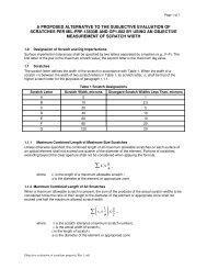
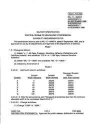
3.5.1.1 Designation of defect size. Limiting sizes of surface defects shall be<br />
designated on the drawings by two numbers which refer to two graded sets of<br />
surface quality standards per Drawing C7641866. The first number shall refer<br />
to scratches and the second number shall refer to digs (see 6.3).<br />
3.5.2 Scratches.<br />
3.5.2.1 Circular element. The combined length of maximum size scratches<br />
3<br />
Source: http://www.assistdocs.com -- Downloaded: 2006-05-24T15:32Z<br />
Check the source to verify that this is the current version before use.