Examples of Automation X-SEL Serial Communication 2 - IGAS
Examples of Automation X-SEL Serial Communication 2 - IGAS
Examples of Automation X-SEL Serial Communication 2 - IGAS
Create successful ePaper yourself
Turn your PDF publications into a flip-book with our unique Google optimized e-Paper software.
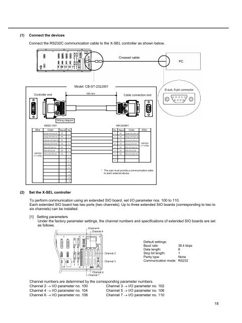
(1) Connect the devices<br />
Connect the RS232C communication cable to the X-<strong>SEL</strong> controller as shown below.<br />
(2) Set the X-<strong>SEL</strong> controller<br />
To perform communication using an extended SIO board, set I/O parameter nos. 100 to 110.<br />
Each extended SIO board has two ports (two channels). Up to three extended SIO boards (corresponding to two to<br />
six channels) can be installed.<br />
[1] Setting parameters<br />
Under the factory parameter settings, the channel numbers and specifications <strong>of</strong> extended SIO boards are set<br />
as follows.<br />
Model: CB-ST-232J001<br />
Channel 6<br />
Channel 4<br />
Channel 5<br />
Channel 7<br />
Channel 2<br />
Channel 3<br />
Crossed cable<br />
100 mm<br />
Controller end Cable connection end<br />
Wiring diagram<br />
XM2D-1501 XM-2A0901<br />
Wire Color Signal No. No. Signal Color Wire<br />
Orange with black dot SD 1<br />
Orange with black dot RD 2<br />
Light gray with black dot RS 3<br />
Light gray with red dot CS 4<br />
White with black dot ER 5<br />
White with red dot DR 6<br />
AWG24 Yellow with black dot<br />
x 7 cores<br />
SG 7<br />
8<br />
9<br />
10<br />
11<br />
12<br />
13<br />
14<br />
15<br />
AWG24<br />
x 7 cores<br />
Channel numbers are determined by the corresponding parameter numbers.<br />
Channel 2 → I/O parameter no. 100 Channel 3 → I/O parameter no. 102<br />
Channel 4 → I/O parameter no. 104 Channel 5 → I/O parameter no. 106<br />
Channel 6 → I/O parameter no. 108 Channel 7 → I/O parameter no. 110<br />
3<br />
2<br />
7<br />
8<br />
4<br />
6<br />
5<br />
1<br />
9<br />
SD Orange with black dot<br />
RD Orange with black dot<br />
RS Light gray with black dot<br />
CS Light gray with red dot<br />
ER White with black dot<br />
DR White with red dot<br />
SG Yellow with black dot<br />
* The user must provide a communication cable<br />
to each external device.<br />
PC<br />
D-sub, 9-pin connector<br />
Default settings:<br />
Baud rate: 38.4 kbps<br />
Data length: 8<br />
Stop bit length: 1<br />
Parity type: None<br />
<strong>Communication</strong> mode: RS232<br />
18


