Examples of Automation X-SEL Serial Communication 2 - IGAS
Examples of Automation X-SEL Serial Communication 2 - IGAS
Examples of Automation X-SEL Serial Communication 2 - IGAS

Create successful ePaper yourself
Turn your PDF publications into a flip-book with our unique Google optimized e-Paper software.
About IP Address<br />
The IP address is an identification number assigned to each device communicating over Ethernet.<br />
Each address consists <strong>of</strong> four three-digit integers (0 to 255) separated by dots. The first three integers comprise an<br />
identification number used by all devices to connect to the same network, while the last integer serves as a device number.<br />
All communicating devices must have the same integers in the first three positions <strong>of</strong> their IP addresses; otherwise, they do<br />
not recognize one another as belonging to the same group. However, the last device number must be unique for each<br />
device, as duplicate device numbers disables communication.<br />
Exercise caution when setting IP addresses, because communication cannot be established if IP addresses are set<br />
incorrectly.<br />
Before establishing communication, port numbers must also be specified for communicating devices together with IP<br />
addresses.<br />
In this example, the stations are set as follows.<br />
Type Connected device IP address Port nos.<br />
Server DVT camera 192.168.0.53 5005<br />
Client X-<strong>SEL</strong> controller 192.168.0.1 64512<br />
The setting procedure based on the above specifications is explained step by step.<br />
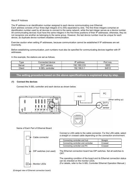
(1) Connect the devices<br />
Connect the X-<strong>SEL</strong> controller and each device as shown below.<br />
Name <strong>of</strong> Each Part <strong>of</strong> Ethernet Board<br />
Cable connector<br />
DIP switches (not used)<br />
Monitor LEDs<br />
(Enlarged view <strong>of</strong> Ethernet connection board)<br />
Connect a LAN cable to the cable connector. For the LAN cable, select<br />
a straight or crossed cable depending on the connection environment.<br />
Connecting controller and hub Straight<br />
Connecting controller and controller Crossed<br />
Connecting controller and PC Crossed<br />
The Ethernet connection board has DIP switches. Set all switches to<br />
OFF.<br />
The operating condition <strong>of</strong> the board and its Ethernet connection status<br />
can be checked on the monitor LEDs.<br />
(For details, refer to the X-<strong>SEL</strong> Controller Ethernet Operation Manual.)<br />
PC<br />
(When setting up)<br />
DVT’s<br />
smart<br />
sensor