Download File - Hawk Measurement Systems!
Download File - Hawk Measurement Systems!
Download File - Hawk Measurement Systems!

You also want an ePaper? Increase the reach of your titles
YUMPU automatically turns print PDFs into web optimized ePapers that Google loves.
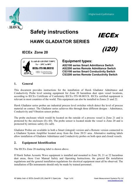
Safety instructions<br />
HAWK GLADIATOR SERIES<br />
IECEx Zone 20<br />
IECEx<br />
(i20)<br />
Equipment types:<br />
AS2100 series Smart Admittance Switch<br />
AS2200 series Remote Admittance Switch<br />
CS3100 series Smart Conductivity Switch<br />
CS3200 series Remote Conductivity Switch<br />
1. General<br />
This document provides instructions for the installation of <strong>Hawk</strong> Gladiator Admittance and<br />
Conductivity Probe level sensing equipment for Zone 20 hazardous dust open vessel locations,<br />
according to IECEx Certificate of Conformity IECEx ITS 08.0031X. IECEx certified equipment is<br />
relevant in most countries of the world. This equipment can also be installed in Zones 21 and 22.<br />
<strong>Hawk</strong> Gladiator series probes are industrial process level switches which detect the level of process<br />
material on contact. The Gladiator series achieves this through three different designs - Admittance,<br />
Conductivity and Vibration sensor probes.<br />
The probe enclosure which would be located on the outside of a process vessel is Zone 21 and is<br />
protected by the enclosure (Ex tD). The probe sensor is located inside the vessel is Zone 20 and is<br />
protected by intrinsic safety (Ex iaD).<br />
Gladiator Probes are available in both a Smart (integral) version and a Remote version connected to<br />
a Gladiator System Amplifier located away from the Zone 20/21 area. Alternative marking labels<br />
allow installation of Gladiator Admittance and Conductivity probes on both open and closed vessels.<br />
2. Equipment Identification<br />
The IECEx Zone 20 marking label is shown above.<br />
If <strong>Hawk</strong> Sultan Acoustic Wave equipment is installed and mounted in Zone 20, 21 or 22 hazardous<br />
dust areas, these User Manual Safety and Operating Instructions, the general Ex installation<br />
regulations and the general installation regulations for electrical equipment must all be observed. The<br />
installation of Ex instruments should only be made by trained personnel.<br />
40 Safety Instr v2 IECEx Zone20 (i20_Glad RF-C Open).doc Page 1 of 6 <strong>Hawk</strong> <strong>Measurement</strong> <strong>Systems</strong> Pty Ltd<br />
www.hawklevel.com
3. Putting Into Service<br />
To put a <strong>Hawk</strong> Gladiator Unit safely into service, the following steps must be taken:<br />
a) To be compliant, the equipment must be installed with Intrinsic Barrier devices as described in<br />
Section 10, Intrinsic Safe Installation. Cables from both hazardous and safe areas must be<br />
segregated from each other according to the appropriate Intrinsic Safe installation standards.<br />
b) Follow the instructions in Typical Installations and Installation Guide, as well as the relevant<br />
conditions on the IECEx Certificate of Conformity:-<br />
Only to be powered by a suitably certified I.S. Barrier up to and including the values of 28V,<br />
93mA and 651mW.<br />
Parts of the probe are plastic, which may present an electrostatic hazard and should not be<br />
rubbed or cleaned with a dry cloth.<br />
c) Gladiator probes have cable glands located at one side of the housing. The enclosure section<br />
above the process fitting can be rotated to prevent moisture ingress via the cable entries. Ensure<br />
the cable glands are securely tightened to adequately seal the cable. An unused cable entry must<br />
be fitted with the blanking plug and rubber gasket provided.<br />
d) Correct wiring. Follow the instructions in the Wiring sections. Wiring should be in accordance<br />
with relevant installation standards for hazardous area equipment or other local codes of practice.<br />
e) Safe temperature. Temperature must not exceed the operating range of the Gladiator unit. In<br />
particular, Ex rated equipment must not exceed the temperature limits shown on the marking<br />
label.<br />
f) Safe power supply. Power supply values must be according to the Specifications.<br />
g) It is advised to provide a cover for the unit to prevent damage that could happen due to<br />
environmental conditions.<br />
h) Do not put into service where there is a possibility of contact with acetic acid.<br />
4. Use<br />
The instructions for safe use of the Gladiator Unit is as follows:<br />
a) The Gladiator equipment must put into service safely. (see Putting Into Service, above).<br />
b) This User Manual must be read and understood by any person involved with the unit.<br />
c) Environment and installation conditions should be checked regularly.<br />
d) When opening the cover of the any Gladiator unit, prevent dust, liquids or chemical substances<br />
from getting inside the unit. Do not leave any cover open in rain or snow conditions.<br />
e) The Remote Gladiator Probe requires a cable connection to a GSA series Gladiator System<br />
Amplifier. The LCD display is visible through the clear lid of the GSA enclosure.<br />
f) Before making any wiring or hardware configuration changes, it is important to disconnect<br />
power from the equipment.<br />
40 Safety Instr v2 IECEx Zone20 (i20_Glad RF-C Open).doc Page 2 of 6 <strong>Hawk</strong> <strong>Measurement</strong> <strong>Systems</strong> Pty Ltd<br />
www.hawklevel.com
5. Assembling and dismantling<br />
When installing the Gladiator Probe into a threaded nozzle, turn the hexagonal fitting with a suitable<br />
open ended or adjustable spanner. Do not attempt to tighten or remove the unit by gripping the<br />
upper part of the enclosure or lid, because it has almost a full turn of rotational freedom to align the<br />
cable entries.<br />
Moisture and dust must not enter the enclosure. Ensure the lid remains tightly sealed.<br />
Cable entry points must be properly sealed.<br />
6. Installation and Wiring<br />
Carefully follow Typical Installations, Installation Guide and Wiring Diagram sections. Follow<br />
all points listed in Putting Into Service, above. Wiring should be in accordance with relevant<br />
installation standards for hazardous area equipment or other local codes of practice.<br />
7. Adjustment<br />
a) Gladiator Smart Probe models:<br />
User controls and terminal connections can be accessed by unscrewing the lid. A strap wrench tool<br />
can simplify removal of the lid.<br />
See Smart Probe Setup Procedure in the user manual. Make adjustments with the aid of the user<br />
manual if required. Then replace the lid by screwing down tight.<br />
b) Gladiator Remote Probe models:<br />
The Gladiator Remote Probe has a status indicator LED and no user adjustments. The screw lid can<br />
be used to access the wiring terminals. A strap wrench tool can simplify removal of the lid.<br />
To access the user controls on the Gladiator System Amplifier, unlock the clear cover using the lever<br />
on the right hand side of the clear lid. Press this lever in the direction of the arrow (towards the lid)<br />
to release the catch. The lid can then be swung open to gain access to the user control push buttons.<br />
See Remote Probe Setup Procedure in the user manual. Close the lid when finished. To lock the<br />
lid, press on the lower part of the lever, which moves the arrow symbol (in reverse) slightly away<br />
from the lid, locking the lid closed.<br />
c) Software Adjustment:<br />
For software adjustment of Gladiator unit parameter adjustment and data entry, refer to instructions<br />
in Entering Data, and all of the Setup sections. If Gos<strong>Hawk</strong> II software is to be used for parameter<br />
adjustment and data entering from a lap-top computer, read and fully understand the information in<br />
the Gos<strong>Hawk</strong> II Manual either supplied with the equipment or downloaded free from the <strong>Hawk</strong> website:<br />
http://www.hawklevel.com<br />
40 Safety Instr v2 IECEx Zone20 (i20_Glad RF-C Open).doc Page 3 of 6 <strong>Hawk</strong> <strong>Measurement</strong> <strong>Systems</strong> Pty Ltd<br />
www.hawklevel.com
8. Application Conditions<br />
a) Voltage Supply:<br />
Must be according to the voltage supplies given in Specifications.<br />
b) Temperature:<br />
Must not exceed the operating temperature range stated in Putting Into Service, above.<br />
c) Cable Connection:<br />
Cables must only be replaced by the same cable type. If extending the cable, it must be<br />
protected in a junction box and terminated in an enclosure suitable for the environment. Refer<br />
to Wiring sections.<br />
d) Earthing:<br />
<strong>Hawk</strong> Gladiator equipment must be earthed to ensure that shielded cabling is effective.<br />
e) Electrostatic Discharge:<br />
See Putting Into Service (b) above. Do not rub or clean plastic parts with a dry cloth.<br />
f) Industrial Conditions:<br />
This equipment is designed for use in normal industrial conditions relating to humidity,<br />
vibration, etc. If the user intends to operate the equipment in more severe environmental<br />
conditions, the manufacturer or local distributor should be consulted for advice.<br />
9. List of equipment types:<br />
Gladiator Admittance Smart Switch – AS2100 series<br />
Gladiator Admittance Remote Switch – AS2200 series<br />
Gladiator Conductivity Smart Switch – CS3100 series<br />
Gladiator Conductivity Remote Switch – CS3200 series<br />
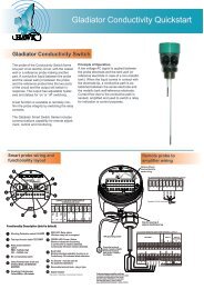
10. Wiring Configuration drawings:<br />
Note: All equipment in Zone 20 Hazardous area must have ATEX Cat 1D marking.<br />
HAW_D_WIR-IS-GLA-004a_.jpg<br />
HAW_D_WIR-IS-GLA-004b_.jpg<br />
40 Safety Instr v2 IECEx Zone20 (i20_Glad RF-C Open).doc Page 4 of 6 <strong>Hawk</strong> <strong>Measurement</strong> <strong>Systems</strong> Pty Ltd<br />
www.hawklevel.com
40 Safety Instr v2 IECEx Zone20 (i20_Glad RF-C Open).doc Page 5 of 6 <strong>Hawk</strong> <strong>Measurement</strong> <strong>Systems</strong> Pty Ltd<br />
www.hawklevel.com
40 Safety Instr v2 IECEx Zone20 (i20_Glad RF-C Open).doc Page 6 of 6 <strong>Hawk</strong> <strong>Measurement</strong> <strong>Systems</strong> Pty Ltd<br />
www.hawklevel.com