Chapter 1 Routine maintenance and servicing
Chapter 1 Routine maintenance and servicing
Chapter 1 Routine maintenance and servicing

You also want an ePaper? Increase the reach of your titles
YUMPU automatically turns print PDFs into web optimized ePapers that Google loves.
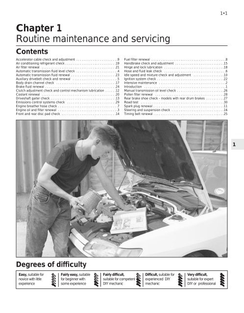
<strong>Chapter</strong> 1<br />
<strong>Routine</strong> <strong>maintenance</strong> <strong>and</strong> <strong>servicing</strong><br />
Contents<br />
Accelerator cable check <strong>and</strong> adjustment . . . . . . . . . . . . . . . . . . . . . . .9<br />
Air conditioning refrigerant check . . . . . . . . . . . . . . . . . . . . . . . . . . . .19<br />
Air filter renewal . . . . . . . . . . . . . . . . . . . . . . . . . . . . . . . . . . . . . . . . .21<br />
Automatic transmission fluid level check . . . . . . . . . . . . . . . . . . . . . . .4<br />
Automatic transmission fluid renewal . . . . . . . . . . . . . . . . . . . . . . . . .23<br />
Auxiliary drivebelt check <strong>and</strong> renewal . . . . . . . . . . . . . . . . . . . . . . . . .5<br />
Body drain channel check . . . . . . . . . . . . . . . . . . . . . . . . . . . . . . . . .17<br />
Brake fluid renewal . . . . . . . . . . . . . . . . . . . . . . . . . . . . . . . . . . . . . . .24<br />
Clutch adjustment check <strong>and</strong> control mechanism lubrication . . . . . .12<br />
Coolant renewal . . . . . . . . . . . . . . . . . . . . . . . . . . . . . . . . . . . . . . . . .20<br />
Driveshaft gaiter check . . . . . . . . . . . . . . . . . . . . . . . . . . . . . . . . . . . .13<br />
Emissions control systems check . . . . . . . . . . . . . . . . . . . . . . . . . . .29<br />
Engine breather hose check . . . . . . . . . . . . . . . . . . . . . . . . . . . . . . . . .7<br />
Engine oil <strong>and</strong> filter renewal . . . . . . . . . . . . . . . . . . . . . . . . . . . . . . . . .3<br />
Front <strong>and</strong> rear disc pad check . . . . . . . . . . . . . . . . . . . . . . . . . . . . . .14<br />
1•1<br />
Fuel filter renewal . . . . . . . . . . . . . . . . . . . . . . . . . . . . . . . . . . . . . . . . .8<br />
H<strong>and</strong>brake check <strong>and</strong> adjustment . . . . . . . . . . . . . . . . . . . . . . . . . . .15<br />
Hinge <strong>and</strong> lock lubrication . . . . . . . . . . . . . . . . . . . . . . . . . . . . . . . . .18<br />
Hose <strong>and</strong> fluid leak check . . . . . . . . . . . . . . . . . . . . . . . . . . . . . . . . . .6<br />
Idle speed <strong>and</strong> mixture check <strong>and</strong> adjustment . . . . . . . . . . . . . . . . .10<br />
Ignition system check . . . . . . . . . . . . . . . . . . . . . . . . . . . . . . . . . . . . .22<br />
Intensive <strong>maintenance</strong> . . . . . . . . . . . . . . . . . . . . . . . . . . . . . . . . . . . . .2<br />
Introduction . . . . . . . . . . . . . . . . . . . . . . . . . . . . . . . . . . . . . . . . . . . . .1<br />
Manual transmission oil level check . . . . . . . . . . . . . . . . . . . . . . . . . .26<br />
Pollen filter renewal . . . . . . . . . . . . . . . . . . . . . . . . . . . . . . . . . . . . . .28<br />
Rear brake shoe check - models with rear drum brakes . . . . . . . . . .27<br />
Road test . . . . . . . . . . . . . . . . . . . . . . . . . . . . . . . . . . . . . . . . . . . . . .30<br />
Spark plug renewal . . . . . . . . . . . . . . . . . . . . . . . . . . . . . . . . . . . . . . .11<br />
Steering <strong>and</strong> suspension check . . . . . . . . . . . . . . . . . . . . . . . . . . . . .16<br />
Timing belt renewal . . . . . . . . . . . . . . . . . . . . . . . . . . . . . . . . . . . . . . .25<br />
1<br />
Degrees of difficulty<br />
Easy, suitable for<br />
novice with little<br />
experience<br />
Fairly easy, suitable<br />
for beginner with<br />
some experience<br />
Fairly difficult,<br />
suitable for competent<br />
DIY mechanic<br />
Difficult, suitable for<br />
experienced DIY<br />
mechanic<br />
Very difficult,<br />
suitable for expert<br />
DIY or professional
1•2 Servicing Specifications<br />
Lubricants <strong>and</strong> fluids<br />
Refer to the end of “Weekly checks”<br />
Capacities<br />
Engine oil<br />
TU engine - with filter . . . . . . . . . . . . . . . . . . . . . . . . . . . . . . . . . . . . . . .<br />
TU engine - without filter . . . . . . . . . . . . . . . . . . . . . . . . . . . . . . . . . . . .<br />
XU engine (8-valve) - with filter . . . . . . . . . . . . . . . . . . . . . . . . . . . . . . . .<br />
XU engine (8-valve) - without filter . . . . . . . . . . . . . . . . . . . . . . . . . . . . .<br />
XU engine (16-valve) - with filter . . . . . . . . . . . . . . . . . . . . . . . . . . . . . . .<br />
XU engine (16-valve) - without filter . . . . . . . . . . . . . . . . . . . . . . . . . . . .<br />
Cooling system (approximate) . . . . . . . . . . . . . . . . . . . . . . . . . . . . . . .<br />
Manual gearbox . . . . . . . . . . . . . . . . . . . . . . . . . . . . . . . . . . . . . . . . . .<br />
Automatic transmission:<br />
Drain <strong>and</strong> refill . . . . . . . . . . . . . . . . . . . . . . . . . . . . . . . . . . . . . . . . . . .<br />
After overhaul . . . . . . . . . . . . . . . . . . . . . . . . . . . . . . . . . . . . . . . . . . .<br />
Power steering system . . . . . . . . . . . . . . . . . . . . . . . . . . . . . . . . . . . . .<br />
Fuel tank . . . . . . . . . . . . . . . . . . . . . . . . . . . . . . . . . . . . . . . . . . . . . . . .<br />
3.5 litres<br />
3.2 litres<br />
5.0 litres<br />
4.5 litres<br />
5.3 litres<br />
5.0 litres<br />
7.0 litres<br />
2.0 litres<br />
2.4 litres<br />
6.2 litres<br />
0.7 litres<br />
70 litres<br />
Engine<br />
Oil filter type . . . . . . . . . . . . . . . . . . . . . . . . . . . . . . . . . . . . . . . . . . . . . . Champion F104<br />
Cooling system<br />
Antifreeze mixture:<br />
28% antifreeze . . . . . . . . . . . . . . . . . . . . . . . . . . . . . . . . . . . . . . . . . . Protection down to -15°C(-5°F)<br />
50% antifreeze . . . . . . . . . . . . . . . . . . . . . . . . . . . . . . . . . . . . . . . . . . Protection down to -30°C(-22°F)<br />
Fuel system<br />
Idle speed:<br />
TU carburettor engine . . . . . . . . . . . . . . . . . . . . . . . . . . . . . . . . . . . . 850 ± 50 rpm<br />
XU carburettor engine . . . . . . . . . . . . . . . . . . . . . . . . . . . . . . . . . . . . 900 ± 50 rpm<br />
XU5 <strong>and</strong> TU3 single-point injection (not adjustable) . . . . . . . . . . . . . 850 ± 50 rpm<br />
Bosch L3.1 multi-point injection . . . . . . . . . . . . . . . . . . . . . . . . . . . . . 925 ± 25 rpm<br />
Other multi-point injection systems (not adjustable) . . . . . . . . . . . . . 850 ± 50 rpm<br />
Idle mixture CO content:<br />
TU carburettor engine . . . . . . . . . . . . . . . . . . . . . . . . . . . . . . . . . . . . . 0.8%<br />
XU carburettor engine . . . . . . . . . . . . . . . . . . . . . . . . . . . . . . . . . . . . . 0.5%<br />
XU5 <strong>and</strong> TU3 single-point injection (not adjustable) . . . . . . . . . . . . . Less than 0.5 %<br />
XU5, XU7, XU9, XU10 multi-point injection (not adjustable) . . . . . . . Less than 1.0 %<br />
Air filter element:<br />
TU engine . . . . . . . . . . . . . . . . . . . . . . . . . . . . . . . . . . . . . . . . . . . . . . Champion V401<br />
XU engine . . . . . . . . . . . . . . . . . . . . . . . . . . . . . . . . . . . . . . . . . . . . . . Champion U543<br />
Fuel filter . . . . . . . . . . . . . . . . . . . . . . . . . . . . . . . . . . . . . . . . . . . . . . . . . Champion L101, L206, L132 or L135<br />
Ignition system<br />
Spark plugs:<br />
TU <strong>and</strong> XU carburettor engines . . . . . . . . . . . . . . . . . . . . . . . . . . . . . Champion C9YCC<br />
XU injection 8-valve engines . . . . . . . . . . . . . . . . . . . . . . . . . . . . . . . . Champion C7YCC<br />
XU injection16-valve engines . . . . . . . . . . . . . . . . . . . . . . . . . . . . . . . Champion RC7BMC<br />
Spark plug electrode gap*:<br />
8-valve engines . . . . . . . . . . . . . . . . . . . . . . . . . . . . . . . . . . . . . . . . . . 0.8 mm<br />
16-valve engines . . . . . . . . . . . . . . . . . . . . . . . . . . . . . . . . . . . . . . . . . 1.6 mm<br />
Ignition HT lead resistance . . . . . . . . . . . . . . . . . . . . . . . . . . . . . . . . . . . Approximately 600 ohms per 100 mm length<br />
*The spark plug gap quoted is that recommended by Champion for their specified plugs listed above.<br />
Brakes<br />
Front/rear brake pad friction material minimum thickness . . . . . . . . . . . 2.0 mm<br />
Rear brake shoe friction material minimum thickness . . . . . . . . . . . . . . 1.0 mm<br />
Tyre pressures<br />
See end of “Weekly Checks”.<br />
Torque wrench settings Nm lbf ft<br />
Engine oil drain plug . . . . . . . . . . . . . . . . . . . . . . . . . . . . . . . . . . . . . . . . 27 20<br />
Manual gearbox drain plug . . . . . . . . . . . . . . . . . . . . . . . . . . . . . . . . . . 30 22<br />
Roadwheel bolts . . . . . . . . . . . . . . . . . . . . . . . . . . . . . . . . . . . . . . . . . . . 85 63<br />
Spark plugs . . . . . . . . . . . . . . . . . . . . . . . . . . . . . . . . . . . . . . . . . . . . . . . 27 20
Maintenance schedule - models up to 1993 1•3<br />
The <strong>maintenance</strong> intervals in this manual<br />
are provided with the assumption that you will<br />
be carrying out the work yourself. These are<br />
the minimum <strong>maintenance</strong> intervals<br />
recommended by the manufacturer for<br />
vehicles driven daily. If you wish to keep your<br />
vehicle in peak condition at all times, you may<br />
wish to perform some of these procedures<br />
more often. We encourage frequent<br />
<strong>maintenance</strong>, because it enhances the<br />
efficiency, performance <strong>and</strong> resale value of<br />
your vehicle.<br />
If the vehicle is driven in dusty areas, used<br />
to tow a trailer, or driven frequently at slow<br />
speeds (idling in traffic) or on short journeys,<br />
more frequent <strong>maintenance</strong> intervals are<br />
recommended.<br />
When the vehicle is new, it should be<br />
serviced by a factory-authorised dealer<br />
service department, in order to preserve the<br />
factory warranty.<br />
Every 250 miles (400 km) or weekly<br />
Refer to “Weekly checks”<br />
Every 6000 miles (10 000 km) or<br />
6 months - whichever comes sooner<br />
Renew engine oil <strong>and</strong> filter (Section 3)<br />
Check the automatic transmission fluid level<br />
(Section 4)<br />
Check the condition of the auxiliary drivebelt<br />
(Section 5)<br />
Check all underbonnet components for fluid leaks<br />
(Section 6)<br />
Every 12 000 miles (20 000 km) or<br />
12 months - whichever comes sooner<br />
In addition to all the items listed above, carry out the following:<br />
Check condition <strong>and</strong> security of engine breather<br />
hoses (Section 7)<br />
Renew the fuel filter (Section 8)<br />
Check the condition of, <strong>and</strong> adjust as necessary,<br />
the accelerator cable (Section 9)<br />
Check the idle speed <strong>and</strong> mixture (CO) adjustment.<br />
Clean the fuel filter in the carburettor (where<br />
applicable) (Section 10)<br />
Renew the spark plugs (Section 11)<br />
Check <strong>and</strong> adjust the clutch pedal travel<br />
(Section 12)<br />
Check the condition of the driveshaft rubber gaiters<br />
(Section 13)<br />
Check front <strong>and</strong> rear disc brake pads for wear<br />
(Section 14)<br />
Check the operation of the h<strong>and</strong>brake <strong>and</strong> adjust<br />
as necessary (Section 15)<br />
Check the steering <strong>and</strong> suspension components<br />
(Section 16)<br />
Check <strong>and</strong> unblock all door <strong>and</strong> sill drain channels.<br />
Also check the heater drain tube (Section 17)<br />
Every 18 000 miles (30 000 km) or<br />
18 months - whichever comes sooner<br />
In addition to all the items listed above, carry out the following:<br />
Lubricate all hinges <strong>and</strong> locks (Section 18)<br />
Check the air conditioning system refrigerant<br />
(Section 19)<br />
Every 24 000 miles (40 000 km) or<br />
2 years - whichever comes sooner<br />
In addition to all the items listed above, carry out the following:<br />
Renew the coolant (Section 20)<br />
Renew the air filter element (Section 21)<br />
Check the ignition system <strong>and</strong> ignition timing<br />
(Section 22)<br />
Renew the automatic transmission fluid<br />
(Section 23)<br />
Renew the hydraulic fluid in the braking system<br />
(Section 24)<br />
Every 36 000 miles (60 000 km) or<br />
3 years - whichever comes sooner<br />
In addition to all the items listed above, carry out the following:<br />
Renew the timing belt (Section 25)<br />
Check <strong>and</strong> if necessary top-up the manual<br />
transmission oil level (Section 26)<br />
Inspect the rear brake drum linings for wear<br />
(Section 27)<br />
1
1•4 Maintenance schedule - models from 1994<br />
The <strong>maintenance</strong> schedule for models from<br />
1994 is given below. When compared with the<br />
schedule for earlier models, it will be seen that<br />
although the same operations are required, the<br />
frequency with which they are performed has<br />
changed considerably. The specified interval<br />
for most operations has been extended.<br />
The description of the <strong>maintenance</strong> tasks in<br />
this <strong>Chapter</strong> follows the schedule prescribed<br />
Every 250 miles (400 km) or weekly<br />
Refer to “Weekly checks”<br />
Every 9000 miles (15 000 km) or<br />
12 months - whichever comes sooner<br />
Note: It is strongly recommended that the engine oil <strong>and</strong> filter be<br />
changed at least every 6 months, even if the mileage specified has<br />
not been covered.<br />
Renew engine oil <strong>and</strong> filter (Section 3)<br />
Check the clutch adjustment (Section 12)<br />
Check all underbonnet components for fluid leaks<br />
(Section 6)<br />
Check the steering <strong>and</strong> suspension components<br />
(Section 16)<br />
Check the condition of the driveshaft rubber gaiters<br />
(Section 13)<br />
Check the automatic transmission fluid level<br />
(Section 4)<br />
Renew the pollen filter where fitted (Section 28)<br />
for earlier models. When the interval for later<br />
models varies, this is of course indicated.<br />
However, the DIY owner may consider that it<br />
is well worth while observing the shorter<br />
intervals in any case.<br />
We encourage frequent <strong>maintenance</strong>,<br />
because it enhances the efficiency,<br />
performance <strong>and</strong> ultimately, the resale value<br />
of your vehicle.<br />
If the vehicle is driven in dusty areas, is<br />
used to tow a trailer, or driven frequently at<br />
slow speeds (idling in traffic) or on short<br />
journeys, more frequent <strong>maintenance</strong> intervals<br />
are recommended.<br />
When the vehicle is new, it should be<br />
serviced by a factory-authorised dealer<br />
service department, in order to preserve the<br />
factory warranty.<br />
Every 36 000 miles (60 000 km)<br />
In addition to all the items listed above, carry out the following:<br />
Lubricate all hinges <strong>and</strong> locks (Section 18)<br />
Renew the air filter (Section 21)<br />
Inspect the rear brake drum linings for wear<br />
(Section 27)<br />
Check the condition of the rear disc brake pads<br />
(Section 14)<br />
Check <strong>and</strong> if necessary top-up the manual<br />
transmission oil level (Section 26)<br />
Renew the fuel filter - fuel injection models<br />
(Section 8)<br />
Renew the timing belt (Section 25) see Note below.<br />
Note: Although the normal interval for timing belt renewal is<br />
72 000 miles (120 000 km), it is strongly recommended that the<br />
interval is halved to 36 000 miles (60 000 km) on vehicles which<br />
are subjected to intensive use, ie. mainly short journeys or a lot<br />
of stop-start driving. The actual belt renewal interval is<br />
therefore very much up to the individual owner, but bear in<br />
mind that severe engine damage will result if the belt breaks.<br />
Every 18 000 miles (30 000 km)<br />
In addition to all the items listed above, carry out the following:<br />
Check the air conditioning system refrigerant<br />
(Section 19)<br />
Renew the spark plugs (Section 11)<br />
Renew the fuel filter - carburettor models<br />
(Section 8)<br />
Renew the automatic transmission fluid<br />
(Section 23)<br />
Check the ignition system <strong>and</strong> ignition timing<br />
(Section 22)<br />
Check the idle speed <strong>and</strong> mixture adjustment<br />
(Section 10)<br />
Check the emissions control system components<br />
(Section 29)<br />
Check the condition of the auxiliary drivebelt<br />
(Section 5)<br />
Lubricate the clutch control mechanism<br />
(Section 12)<br />
Check the condition of the front brake pads<br />
(Section 14)<br />
Check the operation of the h<strong>and</strong>brake (Section 15)<br />
Carry out a road test (Section 30)<br />
Every 72 000 miles (120 000 km)<br />
In addition to all the items listed above, carry out the following:<br />
Renew the timing belt (Section 25) - this is the<br />
interval recommended by Peugeot, but we<br />
recommend that the belt is changed more<br />
frequently, at 36 000 miles - see above.<br />
Every 2 years<br />
(regardless of mileage)<br />
Renew the coolant (Section 20)<br />
Renew the brake fluid (Section 24)
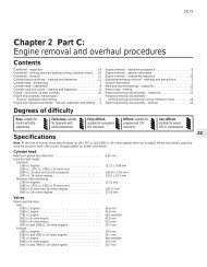
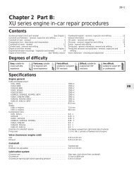
Underbonnet view of a 1580 cc carburettor engine<br />
Maintenance & Servicing 1•5<br />
1 Left-h<strong>and</strong> suspension strut<br />
top mounting<br />
2 Battery<br />
3 Air filter housing<br />
4 Cold air inlet duct<br />
5 Bonnet lock<br />
6 Bonnet release latch<br />
7 Engine oil filler cap/tube<br />
8 Carburettor air inlet duct<br />
(carburettor below)<br />
9 Radiator (coolant filler) cap<br />
10 Alternator<br />
11 Right-h<strong>and</strong> engine mounting<br />
12 Timing belt upper cover<br />
13 Right-h<strong>and</strong> suspension strut<br />
top mounting<br />
14 Windscreen wash reservoir<br />
15 Brake hydraulic fluid reservoir<br />
16 Camshaft cover<br />
17 Windscreen wiper motor<br />
(beneath cover)<br />
18 Hot air inlet duct<br />
19 Engine oil level dipstick<br />
20 Fuel pump<br />
21 Distributor<br />
22 Spark plug HT leads<br />
1<br />
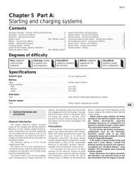
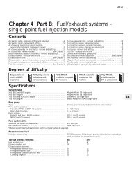
Underbonnet view of a 1580 cc fuel injection engine<br />
1 Brake hydraulic fluid reservoir<br />
2 Valve cover<br />
3 Windscreen wiper motor<br />
(beneath cover)<br />
4 Engine oil level dipstick<br />
5 Hot air duct<br />
6 Left-h<strong>and</strong> suspension strut<br />
top mounting<br />
7 Battery<br />
8 Power steering fluid reservoir<br />
9 Air cleaner<br />
10 Engine oil filler cap/tube<br />
11 Radiator (coolant filler) cap<br />
12 Alternator<br />
13 Right-h<strong>and</strong> engine mounting<br />
14 Windscreen washer reservoir
1•6 Maintenance & Servicing<br />
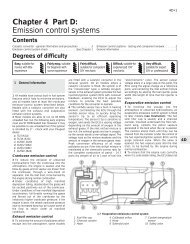
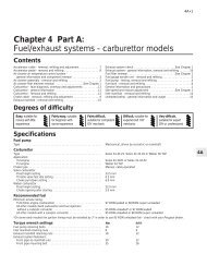
Underbonnet view of a 1905 cc engine<br />
1 Left-h<strong>and</strong> strut top mounting<br />
2 Battery<br />
3 Fuel damper<br />
4 Power steering fluid reservoir<br />
5 Air filter cover<br />
6 Fuel injection control unit<br />
7 Thermostat housing<br />
8 Cold air inlet<br />
9 Throttle housing<br />
10 Brake servo vacuum hose<br />
11 Bonnet lock<br />
12 Inlet manifold<br />
13 Bonnet release latch<br />
14 Accelerator cable<br />
15 Radiator (coolant filler cap)<br />
16 Alternator<br />
17 Right-h<strong>and</strong> engine mounting<br />
18 Fuel injection relay box<br />
19 Right-h<strong>and</strong> strut top mounting<br />
20 Camshaft drivebelt top cover<br />
21 Fuel pressure regulator<br />
22 Engine oil filler tube<br />
23 Earth lead<br />
24 Windscreen washer reservoir<br />
25 Brake hydraulic fluid reservoir<br />
26 Brake servo vacuum unit<br />
27 Windscreen wiper motor<br />
28 Fuel rail <strong>and</strong> injectors<br />
29 Camshaft cover<br />
30 Power steering hose<br />
31 Engine oil level dipstick<br />
32 Windscreen wiper arm<br />
33 Air inlet grille (ventilation)<br />
34 Distributor<br />
Underbonnet view of a 1998 cc engine<br />
1 Brake system hydraulic fluid<br />
reservoir<br />
2 Engine oil filler cap<br />
3 Windscreen wiper motor<br />
(below cover)<br />
4 Air cleaner cover<br />
5 Ignition coil<br />
6 Left-h<strong>and</strong> suspension strut<br />
top mounting<br />
7 Battery<br />
8 Power steering fluid reservoir<br />
9 Inlet air duct<br />
10 Engine oil level dipstick<br />
11 Automatic transmission<br />
kickdown cable<br />
12 Throttle housing<br />
13 Accelerator cable<br />
14 Radiator (coolant filler cap)<br />
15 Auxiliary drivebelt<br />
16 Windscreen washer fluid<br />
reservoir
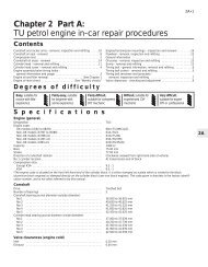
Front underbody view of a 1905 cc engine model<br />
Maintenance & Servicing 1•7<br />
1 Fuel lines<br />
2 Front exhaust silencer<br />
3 Brake lines<br />
4 Front subframe rear mounting<br />
5 Steering rack mountings<br />
6 Exhaust downpipe<br />
7 Steering tack rod<br />
8 Lower suspension arm<br />
9 Radiator lower hose<br />
10 Engine oil sump<br />
11 Rear engine mounting<br />
12 Driveshaft intermediate<br />
bearing housing<br />
13 Right-h<strong>and</strong> driveshaft<br />
14 Oil temperature sensor<br />
15 Engine oil drain plug<br />
16 Radiator<br />
17 Transmission housing<br />
18 Differential housing<br />
19 Cooling fan resistor<br />
20 Horn<br />
1<br />
Rear underbody view of a 1905 cc engine model<br />
1 Fuel tank<br />
2 Fuel tank supporting strap<br />
3 Heat shield<br />
4 Exhaust pipe<br />
5 Rear suspension side member<br />
6 H<strong>and</strong>brake cable equaliser<br />
mechanism<br />
7 Rear suspension torsion bar<br />
8 Rear shock absorber<br />
9 Rear disc brake caliper<br />
10 Exhaust rear silencer<br />
11 Spare wheel (cover removed)<br />
12 Spare wheel cradle support<br />
hook<br />
13 Fuel filler hose<br />
14 Rear anti-roll bar<br />
15 Suspension cross-link
1•8 6000 Mile / 6 Month Service<br />
Maintenance procedures<br />
1 Introduction<br />
General information<br />
1 This <strong>Chapter</strong> is designed to help the home<br />
mechanic maintain his/her vehicle for safety,<br />
economy, long life <strong>and</strong> peak performance.<br />
2 The <strong>Chapter</strong> contains a master<br />
<strong>maintenance</strong> schedule, followed by Sections<br />
dealing specifically with each task in the<br />
schedule. Visual checks, adjustments,<br />
component renewal <strong>and</strong> other helpful items<br />
are included. Refer to the accompanying<br />
illustrations of the engine compartment <strong>and</strong><br />
the underside of the vehicle for the locations<br />
of the various components.<br />
3 Servicing your vehicle in accordance with<br />
the mileage/time <strong>maintenance</strong> schedule <strong>and</strong><br />
the following Sections will provide a planned<br />
<strong>maintenance</strong> programme, which should result<br />
in a long <strong>and</strong> reliable service life. This is a<br />
comprehensive plan, so maintaining some<br />
items but not others at the specified service<br />
intervals, will not produce the same results.<br />
4 As you service your vehicle, you will<br />
discover that many of the procedures can -<br />
<strong>and</strong> should - be grouped together, because of<br />
the particular procedure being performed, or<br />
because of the close proximity of two<br />
otherwise-unrelated components to one<br />
another. For example, if the vehicle is raised<br />
for any reason, the exhaust can be inspected<br />
at the same time as the suspension <strong>and</strong><br />
steering components.<br />
5 The first step in this <strong>maintenance</strong><br />
programme is to prepare yourself before the<br />
actual work begins. Read through all the<br />
Sections relevant to the work to be carried<br />
out, then make a list <strong>and</strong> gather together all<br />
the parts <strong>and</strong> tools required. If a problem is<br />
encountered, seek advice from a parts<br />
specialist, or a dealer service department.<br />
2 Intensive <strong>maintenance</strong><br />
1 If, from the time the vehicle is new, the<br />
routine <strong>maintenance</strong> schedule is followed<br />
closely, <strong>and</strong> frequent checks are made of fluid<br />
levels <strong>and</strong> high-wear items, as suggested<br />
throughout this manual, the engine will be<br />
kept in relatively good running condition, <strong>and</strong><br />
the need for additional work will be minimised.<br />
2 It is possible that there will be times when<br />
the engine is running poorly due to the lack of<br />
regular <strong>maintenance</strong>. This is even more likely<br />
if a used vehicle, which has not received<br />
regular <strong>and</strong> frequent <strong>maintenance</strong> checks, is<br />
purchased. In such cases, additional work<br />
may need to be carried out, outside of the<br />
regular <strong>maintenance</strong> intervals.<br />
3 If engine wear is suspected, a compression<br />
test will provide valuable information<br />
regarding the overall performance of the main<br />
internal components. Such a test can be used<br />
as a basis to decide on the extent of the work<br />
to be carried out. If, for example, a<br />
compression test indicates serious internal<br />
engine wear, conventional <strong>maintenance</strong> as<br />
described in this <strong>Chapter</strong> will not greatly<br />
improve the performance of the engine, <strong>and</strong><br />
may prove a waste of time <strong>and</strong> money, unless<br />
extensive overhaul work is carried out first.<br />
4 The following series of operations are those<br />
most often required to improve the<br />
performance of a generally poor-running<br />
engine:<br />
Primary operations<br />
a) Clean, inspect <strong>and</strong> test the battery (see<br />
“Weekly checks”).<br />
b) Check all the engine-related fluids (see<br />
“Weekly checks”).<br />
c) Check the condition <strong>and</strong> tension of the<br />
auxiliary drivebelt (Section 5).<br />
d) Renew the spark plugs (Section 11).<br />
e) Inspect the distributor cap <strong>and</strong> HT leads -<br />
as applicable (Section 22).<br />
f) Check the condition of the air cleaner<br />
filter element, <strong>and</strong> renew if necessary<br />
(Section 21).<br />
g) Renew the fuel filter (Section 8).<br />
h) Check the condition of all hoses, <strong>and</strong><br />
check for fluid leaks (Section 6).<br />
i) Check the idle speed <strong>and</strong> mixture settings<br />
- as applicable (Section 10).<br />
5 If the above operations do not prove fully<br />
effective, carry out the following secondary<br />
operations:<br />
Secondary operations<br />
a) Check the charging system (<strong>Chapter</strong> 5A).<br />
b) Check the ignition system (<strong>Chapter</strong> 5B).<br />
c) Check the fuel system (<strong>Chapter</strong> 4).<br />
d) Renew the distributor cap <strong>and</strong> rotor arm -<br />
as applicable (<strong>Chapter</strong> 5B).<br />
e) Renew the ignition HT leads - as<br />
applicable (Section 22).<br />
6000 Mile / 6 Month Service<br />
3 Engine oil <strong>and</strong> filter renewal<br />
1<br />
Note: On models from 1994, the maker’s<br />
specified interval for this procedure is<br />
9000 miles (15 000 km) or 12 months.<br />
Note: A suitable square-section wrench may<br />
be required to undo the sump drain plug on<br />
some models. These wrenches cab be<br />
obtained from most motor factors or your<br />
Peugeot dealer.<br />
1 Frequent oil <strong>and</strong> filter changes are the most<br />
important preventative <strong>maintenance</strong><br />
procedures which can be undertaken by the<br />
DIY owner. As engine oil ages, it becomes<br />
diluted <strong>and</strong> contaminated, which leads to<br />
premature engine wear.<br />
2 Before starting this procedure, gather<br />
together all the necessary tools <strong>and</strong> materials.<br />
Also make sure that you have plenty of clean<br />
rags <strong>and</strong> newspapers h<strong>and</strong>y, to mop up any<br />
spills. Ideally, the engine oil should be warm,<br />
as it will drain better, <strong>and</strong> more built-up<br />
sludge will be removed with it. Take care,<br />
however, not to touch the exhaust or any<br />
other hot parts of the engine when working<br />
under the vehicle. To avoid any possibility of<br />
scalding, <strong>and</strong> to protect yourself from<br />
possible skin irritants <strong>and</strong> other harmful<br />
contaminants in used engine oils, it is<br />
advisable to wear gloves when carrying out<br />
this work. Access to the underside of the<br />
vehicle will be greatly improved if it can be<br />
raised on a lift, driven onto ramps, or jacked<br />
up <strong>and</strong> supported on axle st<strong>and</strong>s (see<br />
“Jacking <strong>and</strong> Vehicle Support”). Whichever<br />
method is chosen, make sure that the vehicle<br />
remains level, or if it is at an angle, so that the<br />
drain plug is at the lowest point. Where<br />
necessary remove the splash guard from<br />
under the engine.<br />
3 Slacken the drain plug about half a turn; on<br />
some models, a square-section wrench may<br />
be needed to slacken the plug (see<br />
illustration). Position the draining container<br />
under the drain plug, then remove the plug<br />
completely. If possible, try to keep the plug<br />
3.3 Slackening the sump drain plug with a<br />
square-section wrench
6000 Mile / 6 Month Service 1•9<br />
As the engine oil drain plug releases<br />
from the threads, move it away sharply<br />
so the stream of oil issuing from the<br />
sump runs into the container, not up<br />
your sleeve!<br />
pressed into the sump while unscrewing it by<br />
h<strong>and</strong> the last couple of turns (see Haynes<br />
Hint) .<br />
4 Recover the sealing ring from the drain<br />
plug.<br />
5 Allow some time for the old oil to drain,<br />
noting that it may be necessary to reposition<br />
the container as the oil flow slows to a trickle.<br />
6 After all the oil has drained, wipe off the<br />
drain plug with a clean rag. Check the sealing<br />
washer for condition, <strong>and</strong> renew it if<br />
necessary. Clean the area around the drain<br />
plug opening, then refit <strong>and</strong> tighten the plug.<br />
7 If the filter is also to be renewed, move the<br />
container into position under the oil filter<br />
which is located on the front side of the<br />
cylinder block, below the inlet manifold.<br />
8 Using an oil filter removal tool if necessary,<br />
slacken the filter initially, then unscrew it by<br />
h<strong>and</strong> the rest of the way (see illustration).<br />
Empty the oil from the old filter into the<br />
container, <strong>and</strong> discard the filter.<br />
9 Use a clean rag to remove all oil, dirt <strong>and</strong><br />
sludge from the filter sealing area on the<br />
engine. Check the old filter to make sure that<br />
the rubber sealing ring hasn’t stuck to the<br />
engine. If it has, carefully remove it.<br />
10 Apply a light coating of clean engine oil to<br />
the sealing ring on the new filter, then screw it<br />
into position on the engine. Tighten the filter<br />
firmly by h<strong>and</strong> only - do not use any tools.<br />
Wipe clean the filter <strong>and</strong> sump drain plug.<br />
3.8 Using an oil filter removal tool to<br />
slacken the oil filter<br />
11 Remove the old oil <strong>and</strong> all tools from<br />
under the car, then lower the car to the<br />
ground (if applicable).<br />
12 Remove the dipstick then unscrew the oil<br />
filler cap from the cylinder head cover. Fill the<br />
engine, using the correct grade <strong>and</strong> type of oil<br />
(see “Weekly checks”). An oil can spout or<br />
funnel may help to reduce spillage. Pour in<br />
half the specified quantity of oil first, then wait<br />
a few minutes for the oil to fall to the sump.<br />
Continue adding oil a small quantity at a time<br />
until the level is up to the lower mark on the<br />
dipstick. Finally, bring the level up to the<br />
upper mark on the dipstick. Insert the<br />
dipstick, <strong>and</strong> refit the filler cap.<br />
13 Start the engine <strong>and</strong> run it for a few<br />
minutes; check for leaks around the oil filter<br />
seal <strong>and</strong> the sump drain plug. Note that there<br />
may be a delay of a few seconds before the oil<br />
pressure warning light goes out when the<br />
engine is first started, as the oil circulates<br />
through the engine oil galleries <strong>and</strong> the new oil<br />
filter, before the pressure builds up.<br />
14 Switch off the engine, <strong>and</strong> wait a few<br />
minutes for the oil to settle in the sump once<br />
more. With the new oil circulated <strong>and</strong> the filter<br />
completely full, recheck the level on the<br />
dipstick, <strong>and</strong> add more oil as necessary.<br />
15 Dispose of the used engine oil safely, with<br />
reference to “General Repair Procedures” in<br />
the Reference section of this manual.<br />
Note: It is<br />
antisocial <strong>and</strong><br />
illegal to dump oil<br />
down the drain.<br />
To find the<br />
location of your<br />
local oil recycling<br />
bank, call this<br />
number free.<br />
4 Automatic transmission fluid<br />
level check 1<br />
Note: On models from 1994, the maker’s<br />
specified interval for this procedure is<br />
9000 miles (15 000 km) or 12 months.<br />
1 Take the vehicle on a short journey, to<br />
warm the transmission up to normal operating<br />
temperature, then park the vehicle on level<br />
ground. The fluid level is checked using the<br />
dipstick located at the front of the engine<br />
compartment, directly in front of the<br />
engine/transmission. The dipstick top is<br />
brightly-coloured (usually orange) for easy<br />
identification.<br />
2 With the engine idling <strong>and</strong> the selector lever<br />
in the “P” (Park) position, withdraw the<br />
dipstick from the tube, <strong>and</strong> wipe all the fluid<br />
from its end with a clean rag or paper towel.<br />
Insert the clean dipstick back into the tube as<br />
far as it will go, then withdraw it once more.<br />
Note the fluid level on the end of the dipstick;<br />
it should be between the upper <strong>and</strong> lower<br />
marks (see illustrations).<br />
4.2a Withdrawing the automatic<br />
transmission dipstick<br />
4.2b Automatic transmission fluid dipstick<br />
lower (a) <strong>and</strong> upper (b) fluid level markings<br />
3 If topping-up is necessary, add the required<br />
quantity of the specified fluid to the<br />
transmission via the dipstick tube. Use a<br />
funnel with a fine mesh gauze, to avoid<br />
spillage, <strong>and</strong> to ensure that no foreign matter<br />
enters the transmission. Note: Never overfill<br />
the transmission so that the fluid level is above<br />
the upper mark.<br />
4 After topping-up, take the vehicle on a<br />
short run to distribute the fresh fluid, then<br />
recheck the level again, topping-up if<br />
necessary.<br />
5 Always maintain the level between the two<br />
dipstick marks. If the level is allowed to fall<br />
below the lower mark, fluid starvation may<br />
result, which could lead to severe<br />
transmission damage.<br />
6 Frequent need for topping-up indicates that<br />
there is a leak, which should be found <strong>and</strong><br />
corrected before it becomes serious.<br />
5 Auxiliary drivebelt check<br />
<strong>and</strong> renewal 3<br />
Note: On models from 1994, the maker’s<br />
specified interval for this procedure is<br />
18 000 miles (30 000 km).<br />
Note: Peugeot specify the use of a special<br />
electronic tool (SEEM C.TRONIC type 105 belt<br />
tensioning measuring tool) to correctly set the<br />
auxiliary drivebelt tension. If access to this<br />
equipment cannot be obtained, an<br />
approximate setting can be achieved using<br />
the method described below. If the method<br />
described is used, the tension should be<br />
1
1•10 6000 Mile / 6 Month Service<br />
checked using the special electronic tool at<br />
the earliest opportunity.<br />
1 Except for XU9J4 16-valve engines, all<br />
models are fitted with one auxiliary drivebelt<br />
driven from the crankshaft pulley on the righth<strong>and</strong><br />
side of the engine. On non-air<br />
conditioning models the belt drives the<br />
alternator <strong>and</strong> power steering pump <strong>and</strong> its<br />
tension is adjusted manually. On models fitted<br />
with air conditioning it drives the alternator,<br />
power steering pump <strong>and</strong> the air conditioning<br />
compressor. On XU9J4 models a separate<br />
drivebelt drives the power steering pump from<br />
a pulley on the end of the camshaft.<br />
Checking the<br />
auxiliary drivebelt condition<br />
Except XU9J4 16-valve<br />
power steering drivebelt<br />
2 Apply the h<strong>and</strong>brake, then jack up the front<br />
of the car <strong>and</strong> support it on axle st<strong>and</strong>s (see<br />
“Jacking <strong>and</strong> Vehicle Support”). Remove the<br />
right-h<strong>and</strong> front roadwheel.<br />
3 Remove the engine undercover <strong>and</strong><br />
wheelarch cover as applicable.<br />
4 Using a suitable socket <strong>and</strong> extension bar<br />
fitted to the crankshaft sprocket/pulley bolt,<br />
rotate the crankshaft so that the entire length<br />
of the drivebelt can be examined. Examine the<br />
drivebelt for cracks, splitting, fraying or<br />
damage. Check also for signs of glazing (shiny<br />
patches) <strong>and</strong> for separation of the belt plies.<br />
Renew the belt if worn or damaged.<br />
5 If the condition of the belt is satisfactory, on<br />
models where the belt is adjusted manually,<br />
check the drivebelt tension as described<br />
below. On models with an automatic springloaded<br />
tensioner, there is no need to check<br />
the drivebelt tension.<br />
XU9J4 16-valve<br />
power steering drivebelt<br />
6 The power steering drivebelt is positioned<br />
on the left-h<strong>and</strong> end of the cylinder head.<br />
Examine the full length of the drivebelt for<br />
cracks, splitting, fraying or damage. If<br />
necessary turn the engine with a spanner on<br />
the crankshaft pulley or by engaging 4th gear<br />
<strong>and</strong> pushing the car (for safety, the car must<br />
be on level ground). Check also for signs of<br />
glazing (shiny patches) <strong>and</strong> for separation of<br />
the belt plies.<br />
7 If the condition of the belt is satisfactory,<br />
check the drivebelt tension as described later<br />
in this Section.<br />
Auxiliary drivebelt<br />
(early models) - removal,<br />
refitting <strong>and</strong> tensioning<br />
Removal<br />
8 Loosen the alternator pivot <strong>and</strong> link bolts,<br />
then unscrew the adjuster bolt to release the<br />
drivebelt tension (see illustration).<br />
9 Remove the drivebelt from the alternator,<br />
crankshaft <strong>and</strong> where necessary the power<br />
steering pulleys.<br />
5.8 Loosening the alternator adjustment<br />
bolts (early models)<br />
Refitting <strong>and</strong> tensioning<br />
10 Locate the drivebelt on the pulleys making<br />
sure it is correctly engaged with the grooves.<br />
11 The belt tension must be adjusted so that<br />
with moderate thumb pressure applied midway<br />
along the belt’s longest run, it can be<br />
deflected by approximately 6.0 mm. Turn the<br />
adjuster bolt in or out to obtain the correct<br />
tension, then tighten the pivot <strong>and</strong> link bolts<br />
(see illustration).<br />
Auxiliary drivebelt<br />
(models with a manuallyadjusted<br />
tensioning pulley) -<br />
removal, refitting <strong>and</strong> tensioning<br />
Removal<br />
12 If not already done, proceed as described<br />
in paragraphs 2 <strong>and</strong> 3.<br />
13 Disconnect the battery negative lead.<br />
14 Slacken the tensioner pulley bracket<br />
adjustment/mounting bolts (one located in the<br />
middle of the pulley <strong>and</strong> the other located<br />
below on the bracket (see illustration).<br />
15 Fully tighten the adjustment bolt to its<br />
stop, then slip the drivebelt from the pulleys<br />
(see illustration).<br />
Refitting<br />
16 If the belt is being renewed, ensure that<br />
the correct type is used. Fit the belt around<br />
the pulleys, <strong>and</strong> take up the slack in the belt<br />
by tightening the adjuster bolt. Ensure that the<br />
ribs on the belt are correctly engaged with the<br />
grooves in the pulleys.<br />
17 Tension the drivebelt as described in the<br />
following paragraphs.<br />
5.14 Tensioner pulley bracket lower<br />
mounting bolt (arrowed)<br />
5.11 Alternator drivebelt deflection (A)<br />
Tensioning<br />
18 If not already done, proceed as described<br />
in paragraphs 2 <strong>and</strong> 3.<br />
19 Correct tensioning of the drivebelt will<br />
ensure that it has a long life. A belt which is<br />
too slack will slip <strong>and</strong> perhaps squeal.<br />
Beware, however, of overtightening, as this<br />
can cause wear in the alternator bearings.<br />
20 The belt should be tensioned so that,<br />
under firm thumb pressure, there is approximately<br />
5.0 mm of free movement at the midpoint<br />
between the pulleys on the longest belt<br />
run (see the note at the start of this Section).<br />
21 To adjust, unscrew the adjustment bolt<br />
until the tension is correct, then rotate the<br />
crankshaft a couple of times, <strong>and</strong> recheck the<br />
tension. Securely tighten the tensioner pulley<br />
bracket adjustment/mounting bolts.<br />
22 Reconnect the battery negative lead.<br />
23 Refit the engine undercover <strong>and</strong><br />
wheelarch cover. Refit the roadwheel, <strong>and</strong><br />
lower the vehicle to the ground.<br />
Auxiliary drivebelt<br />
(models with an automatic<br />
spring-loaded tensioner pulley) -<br />
removal, refitting <strong>and</strong> tensioning<br />
Removal<br />
24 If not already done, proceed as described<br />
in paragraphs 2 <strong>and</strong> 3.<br />
25 Disconnect the battery negative lead.<br />
26 Using a square drive key in the square<br />
hole in the bottom of the automatic adjuster<br />
bracket, turn the bracket anticlockwise to<br />
release the tension on the belt. Hold the<br />
bracket in this position by inserting a 4.0 mm<br />
5.15 Auxiliary drivebelt tension adjustment<br />
bolt (arrowed)
6000 Mile / 6 Month Service 1•11<br />
37 Remove the bolts <strong>and</strong> lift off the pump.<br />
Refitting <strong>and</strong> tensioning<br />
38 Refit in reverse order, then tension the<br />
belt by applying a torque of 55 Nm for a new<br />
belt <strong>and</strong> 30 Nm for a used belt by using the<br />
square of a torque wrench in the square cutout<br />
in the pump bracket, tightening the<br />
mounting bolts while the torque tension is<br />
maintained (see illustration).<br />
39 Fill <strong>and</strong> bleed the system (see <strong>Chapter</strong> 10).<br />
5.38 Square cut-out in power steering<br />
pump bracket (a) on XU9J4 16-valve models<br />
Allen key through the special hole <strong>and</strong><br />
tightening the peg.<br />
27 Unscrew the mounting bolts <strong>and</strong> remove<br />
the tensioner roller, then slip the auxiliary<br />
drivebelt from the pulleys.<br />
28 Check that the tensioner pulleys turn<br />
freely without any sign of roughness.<br />
Refitting <strong>and</strong> tensioning<br />
29 If the belt is being renewed, ensure that<br />
the correct type is used. Fit the belt around<br />
the pulleys making sure that it is engaged with<br />
the correct grooves in the pulleys.<br />
30 Refit the tensioner roller <strong>and</strong> tighten the<br />
mounting bolts.<br />
31 Using the square drive key hold the<br />
automatic adjuster, then release the peg <strong>and</strong><br />
slowly allow the tensioner to tighten the belt.<br />
Check again that the belt is correctly located<br />
in the pulley grooves.<br />
32 Reconnect the battery negative lead.<br />
33 Refit the engine undercover <strong>and</strong><br />
wheelarch cover. Refit the roadwheel, <strong>and</strong><br />
lower the vehicle to the ground.<br />
Power steering pump drivebelt<br />
(XU9J4 16-valve) models<br />
Removal<br />
34 Drain the hydraulic fluid from the system<br />
as described in <strong>Chapter</strong> 10.<br />
35 Loosen the pump mounting bolts <strong>and</strong><br />
remove the drivebelt.<br />
36 Disconnect the high <strong>and</strong> low pressure<br />
unions on the pump.<br />
6 Hose <strong>and</strong> fluid leak check<br />
1<br />
Note: On models from 1994, the maker’s<br />
specified interval for this procedure is<br />
9000 miles (15 000 km) or 12 months.<br />
1 Visually inspect the engine joint faces,<br />
gaskets <strong>and</strong> seals for any signs of water, oil or<br />
fuel leaks. Pay particular attention to the areas<br />
around the camshaft cover, cylinder head, oil<br />
filter <strong>and</strong> sump joint faces. Bear in mind that,<br />
over a period of time, some slight seepage<br />
from these areas is to be expected. What you<br />
are really looking for is any indication of a<br />
serious leak. Should a leak be found, renew<br />
the offending gasket or oil seal by referring to<br />
the appropriate <strong>Chapter</strong>s in this manual.<br />
2 Also check the security <strong>and</strong> condition of all<br />
the engine-related pipes <strong>and</strong> hoses. Ensure<br />
that all cable-ties or securing clips are in place<br />
<strong>and</strong> in good condition. Clips which are broken<br />
or missing can lead to chafing of the hoses,<br />
pipes, or wiring, which could cause more<br />
serious problems in the future.<br />
3 Carefully check the radiator hoses <strong>and</strong><br />
heater hoses along their entire length. Renew<br />
any hose which is cracked, swollen, or<br />
deteriorated. Cracks will show up better if the<br />
hose is squeezed. Pay close attention to the<br />
hose clips that secure the hoses to the<br />
cooling system components. Hose clips can<br />
pinch <strong>and</strong> puncture hoses, resulting in cooling<br />
system leaks. If the original Peugeot crimpedtype<br />
hose clips are used, it may be a good<br />
idea to replace them with st<strong>and</strong>ard wormdrive<br />
hose clips.<br />
A leak in the cooling system will usually<br />
show up as white or rust coloured<br />
deposits on the area adjoining the leak<br />
4 Inspect the cooling system (hoses, joint<br />
faces, etc.) for leaks (see Haynes Hint).<br />
5 Where any problems of this nature are<br />
found on system components, renew the<br />
component or gasket, referring to <strong>Chapter</strong> 3.<br />
6 Where applicable, inspect the automatic<br />
transmission fluid cooler hoses for leaks or<br />
deterioration.<br />
7 With the vehicle raised, inspect the petrol<br />
tank <strong>and</strong> filler neck for punctures, cracks, <strong>and</strong><br />
other damage. The connection between the<br />
filler neck <strong>and</strong> tank is especially critical.<br />
Sometimes, a rubber filler neck or connecting<br />
hose will leak due to loose retaining clamps or<br />
deteriorated rubber.<br />
8 Carefully check all rubber hoses <strong>and</strong> metal<br />
fuel lines leading away from the petrol tank.<br />
Check for loose connections, deteriorated<br />
hoses, crimped lines, <strong>and</strong> other damage. Pay<br />
particular attention to the vent pipes <strong>and</strong><br />
hoses, which often loop up around the filler<br />
neck, <strong>and</strong> can become blocked or crimped.<br />
Follow the lines to the front of the vehicle,<br />
carefully inspecting them all the way. Renew<br />
damaged sections as necessary.<br />
9 From within the engine compartment,<br />
check the security of all fuel hose attachments<br />
<strong>and</strong> pipe unions, <strong>and</strong> inspect the fuel hoses<br />
<strong>and</strong> vacuum hoses for kinks, chafing <strong>and</strong><br />
deterioration.<br />
10 Where applicable, check the condition of<br />
the power steering fluid hoses <strong>and</strong> pipes.<br />
1<br />
12 000 Mile / 12 Month Service<br />
7 Engine breather hose check<br />
1<br />
Check the condition <strong>and</strong> security of all<br />
engine breather hoses.<br />
Where the engine has covered a high<br />
mileage, remove the hoses <strong>and</strong> clean any<br />
sludge from them.<br />
8 Fuel filter renewal<br />
2<br />
Note:<br />
Warning: Before carrying out<br />
the following operation, refer to<br />
the precautions in “Safety first!”<br />
<strong>and</strong> follow them implicitly.<br />
Petrol is a highly-dangerous <strong>and</strong> volatile<br />
liquid, <strong>and</strong> the precautions necessary<br />
when h<strong>and</strong>ling it cannot be overstressed.<br />
On models from 1994, the maker’s<br />
specified interval for this procedure is 18 000<br />
miles (30 000 km) for carburettor models, <strong>and</strong><br />
36 000 miles (60 000 km) for fuel injection<br />
models.<br />
Carburettor models<br />
1 The fuel filter is connected into the fuel<br />
hose between the pump <strong>and</strong> the carburettor<br />
in the engine compartment (see illustration).<br />
2 To remove the filter, release the retaining<br />
clips <strong>and</strong> disconnect the fuel hoses from the<br />
filter. Where the original Peugeot crimped-
1•12 12 000 Mile / 12 Month Service<br />
8.1 Fuel filter location on<br />
carburettor models<br />
type hose clips are fitted, cut them off <strong>and</strong><br />
discard them; use st<strong>and</strong>ard worm-drive hose<br />
clips on refitting.<br />
3 Note the direction of the arrow marked on<br />
the filter body. Unclip the filter from its<br />
retaining bracket, <strong>and</strong> remove it from the<br />
vehicle.<br />
4 Connect the fuel hoses to the new filter.<br />
Make sure that the arrow on the filter body is<br />
pointing in the direction of the fuel flow, ie.<br />
towards the fuel pump. Secure the hoses in<br />
position by securely tightening the retaining<br />
clips, then clip the filter back into position in<br />
its retaining bracket.<br />
5 At the same time, check the fuel reservoir<br />
tank on the side of the carburettor for sediment.<br />
Remove the reservoir as necessary for cleaning.<br />
6 The fuel connections on the reservoir are as<br />
follows.<br />
a) Top hose - return to tank.<br />
b) Middle hose - supply from pump via filter.<br />
c) Lower hose - to carburettor inlet.<br />
Fuel injection models<br />
7 The fuel filter is situated underneath the rear<br />
of the vehicle, mounted on the right-h<strong>and</strong> side<br />
of the fuel tank. To gain access to the filter,<br />
chock the front wheels, then jack up the rear<br />
of the vehicle <strong>and</strong> support it on axle st<strong>and</strong>s<br />
(see “Jacking <strong>and</strong> Vehicle Support”).<br />
8 Clamp the fuel hose on the tank side of the<br />
filter. Bearing in mind the information given in<br />
the relevant Part of <strong>Chapter</strong> 4 on depressurising<br />
the fuel system, release the clips <strong>and</strong><br />
disconnect the fuel hoses from the filter. Be<br />
prepared for fuel spillage (see illustration).<br />
9 Note the direction of the arrow marked on<br />
the filter body. Slacken the retaining clamp<br />
screw, then slide the filter out of the clamp,<br />
<strong>and</strong> remove it from underneath the vehicle.<br />
10 Dispose safely of the old filter; it will be<br />
highly-inflammable, <strong>and</strong> may explode if<br />
thrown on a fire.<br />
11 Slide the new filter into position in the<br />
clamp, ensuring that the arrow on the filter<br />
body is pointing in the direction of the fuel<br />
flow, ie. towards the throttle body/fuel rail.<br />
This can be determined by tracing the fuel<br />
hoses back along their length.<br />
12 Connect the fuel hoses to the filter, <strong>and</strong><br />
secure them in position with their retaining<br />
clips. Remove the hose clamp.<br />
8.8 Fuel filter on fuel injection models<br />
showing fuel hoses (A) <strong>and</strong> clamp bolt (B)<br />
13 Start the engine, <strong>and</strong> check the filter hose<br />
connections for leaks. Lower the vehicle to<br />
the ground on completion.<br />
9 Accelerator cable check<br />
<strong>and</strong> adjustment 1<br />
Refer to <strong>Chapter</strong> 4A or 4B.<br />
10 Idle speed <strong>and</strong> mixture<br />
check <strong>and</strong> adjustment 3<br />
Note: On models from 1994, the maker’s<br />
specified interval for this procedure is<br />
18 000 miles (30 000 km).<br />
1 Before checking the idle speed <strong>and</strong> mixture<br />
setting, always check the following first:<br />
a) Check that (where adjustable) the ignition<br />
timing is accurate (<strong>Chapter</strong> 5B).<br />
b) Check that the spark plugs are in good<br />
condition <strong>and</strong> correctly gapped (Section 11).<br />
c) Check that the accelerator cable (<strong>and</strong> on<br />
carburettor models, the choke cable) is<br />
correctly adjusted (refer to the relevant<br />
Part of <strong>Chapter</strong> 4).<br />
d) Check that the crankcase breather hoses<br />
are secure, with no leaks or kinks<br />
(Sections 7 <strong>and</strong> 29).<br />
e) Check that the air cleaner filter element is<br />
clean (Section 21).<br />
f) Check that the exhaust system is in good<br />
condition (refer to the relevant Part of<br />
<strong>Chapter</strong> 4).<br />
10.4a Idle speed adjustment screw<br />
(arrowed) on models with idle compensation<br />
g) If the engine is running roughly, check the<br />
compression pressures <strong>and</strong> valve<br />
clearances as described in <strong>Chapter</strong> 2.<br />
h) On fuel injection models, check that the<br />
fuel injection/ignition system warning light<br />
is not illuminated (refer to the relevant<br />
Part of <strong>Chapter</strong> 4).<br />
2 Take the car on a journey of sufficient<br />
length to warm it up to normal operating<br />
temperature. Note: Adjustment should ideally<br />
be completed within two minutes of return,<br />
without stopping the engine. If the radiator<br />
electric cooling fan operates, wait for the<br />
cooling fan to stop. If adjustment takes longer<br />
than stated, regularly clear any excess fuel<br />
from the inlet manifold by revving the engine<br />
two or three times to about 2000 rpm, then<br />
allow it to idle again.<br />
Carburettor models<br />
3 Ensure that all electrical loads are switched<br />
off, <strong>and</strong> that the choke lever is pushed fully in.<br />
If the car does not have a tachometer, connect<br />
one following its manufacturer’s instructions.<br />
Note the idle speed, <strong>and</strong> compare it with that<br />
specified. Note: Models with air conditioning<br />
have an idle compensation device, <strong>and</strong> the air<br />
conditioning compressor must be running<br />
while the idle speed is being checked <strong>and</strong><br />
adjusted.<br />
4 Using a suitable flat-bladed screwdriver,<br />
screw in the idle adjusting screw (to increase<br />
the speed) or out as necessary to obtain the<br />
specified speed. The screw is located on the<br />
carburettor on non-air conditioning models,<br />
<strong>and</strong> on the idle compensating device on air<br />
conditioning models (see illustrations).<br />
5 The idle mixture (exhaust gas CO level) is<br />
set at the factory, <strong>and</strong> should require no<br />
further adjustment. If, due to a change in<br />
engine characteristics (carbon build-up, bore<br />
wear etc) or after a major carburettor<br />
overhaul, the mixture becomes incorrect, it<br />
can be reset. Note, however, that an exhaust<br />
gas analyser (CO meter) will be required to<br />
check the mixture, <strong>and</strong> to set it with the<br />
necessary st<strong>and</strong>ard of accuracy. If this is not<br />
available, the car must be taken to a Peugeot<br />
dealer for the work to be carried out.<br />
6 Follow the exhaust gas analyser<br />
manufacturer’s instructions to check the<br />
exhaust gas CO level. If adjustment is<br />
required, it is made via mixture adjustment<br />
10.4b Idle speed adjustment screw
12 000 Mile / 12 Month Service 1•13<br />
10.7 Idle mixture adjustment screw<br />
(arrowed)<br />
10.10 Adjusting the idle speed screw on<br />
the Bosch L3.1 injection system<br />
10.13 Mixture (CO) adjustment screw on<br />
the Bosch L3.1 injection control unit<br />
screw located on the carburettor. The screw<br />
is covered with a tamperproof plug to prevent<br />
unnecessary adjustment. To gain access to<br />
the screw, use a sharp instrument to hook out<br />
the plug.<br />
7 Using a suitable flat-bladed screwdriver,<br />
turn the mixture adjustment screw by very<br />
small amounts until the level is correct (see<br />
illustration). Screwing it in (clockwise)<br />
weakens the idle mixture <strong>and</strong> reduces the CO<br />
level; screwing it out will richen the mixture<br />
<strong>and</strong> increase the CO level.<br />
8 When adjustments are complete, disconnect<br />
any test equipment, <strong>and</strong> fit a new tamperproof<br />
plug to the mixture adjustment screw. Recheck<br />
the idle speed <strong>and</strong>, if necessary, readjust.<br />
Fuel injection models<br />
Bosch L3.1-Jetronic system<br />
9 Ensure that all electrical loads are switched<br />
off. If the car does not have a tachometer,<br />
connect one following its manufacturer’s<br />
instructions. Note the idle speed, <strong>and</strong><br />
compare it with that specified.<br />
10 The idle speed is adjusted using the idle<br />
speed adjustment screw on the throttle<br />
housing (see illustration). Turn the screw<br />
clockwise to decrease the idle speed, or anticlockwise<br />
to increase the speed.<br />
11 The idle mixture (exhaust gas CO level) is<br />
set at the factory, <strong>and</strong> should require no<br />
further adjustment. If, due to a change in<br />
engine characteristics (carbon build-up, bore<br />
wear etc) or after a major overhaul, the<br />
mixture becomes incorrect, it can be reset.<br />
Note, however, that an exhaust gas analyser<br />
(CO meter) will be required to check the<br />
mixture, <strong>and</strong> to set it with the necessary<br />
st<strong>and</strong>ard of accuracy. If this is not available,<br />
the car must be taken to a Peugeot dealer for<br />
the work to be carried out.<br />
12 Follow the exhaust gas analyser<br />
manufacturer’s instructions to check the<br />
exhaust gas CO level. If adjustment is<br />
required, it is made via mixture adjustment<br />
screw located on the airflow meter (see<br />
<strong>Chapter</strong> 4C). The screw may be covered with<br />
a tamperproof plug to prevent unnecessary<br />
adjustment. To gain access to the screw, use<br />
a sharp instrument to hook out the plug.<br />
13 Using a flat-bladed screwdriver, turn the<br />
mixture adjustment screw by small amounts<br />
until the level is correct (see illustration).<br />
14 When adjustments are complete, disconnect<br />
any test equipment, <strong>and</strong> fit a new tamperproof<br />
plug to the mixture adjustment screw. Recheck<br />
the idle speed <strong>and</strong>, if necessary, readjust.<br />
Bosch ML4.1 Motronic system<br />
15 The idle speed is non-adjustable. It is<br />
controlled by the idle speed regulator valve.<br />
16 The idle mixture (exhaust gas CO level) is<br />
set at the factory, <strong>and</strong> should require no<br />
further adjustment. If, due to a change in<br />
engine characteristics (carbon build-up, bore<br />
wear etc) or after a major overhaul, the<br />
mixture becomes incorrect, it can be reset.<br />
Note, however, that an exhaust gas analyser<br />
(CO meter) will be required to check the<br />
mixture, <strong>and</strong> to set it with the necessary<br />
st<strong>and</strong>ard of accuracy. If this is not available,<br />
the car must be taken to a Peugeot dealer for<br />
the work to be carried out.<br />
17 Follow the exhaust gas analyser<br />
manufacturer’s instructions to check the<br />
exhaust gas CO level. If adjustment is<br />
required, it is made via mixture adjustment<br />
screw located on the airflow meter (see<br />
illustration). The screw may be covered with<br />
a tamperproof plug to prevent unnecessary<br />
adjustment. To gain access to the screw, use<br />
a sharp instrument to hook out the plug.<br />
18 Turn the screw clockwise to increase <strong>and</strong><br />
anti-clockwise to decrease CO content until<br />
the specified CO level is obtained.<br />
19 When adjustments are complete,<br />
disconnect any test equipment, <strong>and</strong> fit a new<br />
tamperproof plug to the mixture adjustment<br />
screw.<br />
Bosch LU2-Jetronic system<br />
20 The idle mixture is not adjustable <strong>and</strong> is<br />
automatically regulated by the ECU.<br />
21 To check the idle speed connect a<br />
tachometer to the engine, then run the engine<br />
at idle speed.<br />
22 Turn the idle speed adjustment screw to<br />
obtain the specified idle speed (see<br />
illustration).<br />
23 When adjustments are complete,<br />
disconnect any test gear from the engine.<br />
Bosch Motronic MP3.1 system<br />
24 Ensure that all electrical loads are<br />
switched off. If the car does not have a<br />
tachometer, connect one following its<br />
manufacturer’s instructions. Note the idle<br />
speed, <strong>and</strong> compare it with that specified.<br />
25 Turn the idle speed adjustment screw to<br />
obtain the specified idle speed (see<br />
illustration).<br />
1<br />
10.17 Mixture (CO) adjustment screw<br />
(arrowed) on Bosch ML4.1 Motronic system<br />
10.22 Idle speed adjustment screw (2) on<br />
the Bosch LU2-Jetronic injection system<br />
10.25 Idle speed adjustment screw (1) on<br />
the Bosch Motronic MP3.1 system
1•14 12 000 Mile / 12 Month Service<br />
10.27 Mixture (CO) adjustment screw (2)<br />
on the Bosch MP3.1 fuel injection system<br />
26 The idle mixture (exhaust gas CO level) is<br />
set at the factory, <strong>and</strong> should require no<br />
further adjustment. If, due to a change in<br />
engine characteristics (carbon build-up, bore<br />
wear etc) or after a major overhaul, the<br />
mixture becomes incorrect, it can be reset.<br />
Note, however, that an exhaust gas analyser<br />
(CO meter) will be required to check the<br />
mixture, <strong>and</strong> to set it with the necessary<br />
st<strong>and</strong>ard of accuracy. If this is not available,<br />
the car must be taken to a Peugeot dealer for<br />
the work to be carried out.<br />
27 Follow the exhaust gas analyser<br />
manufacturer’s instructions to check the<br />
exhaust gas CO level. If adjustment is<br />
required, it is made via mixture adjustment<br />
screw (see illustration). The screw may be<br />
covered with a tamperproof plug to prevent<br />
unnecessary adjustment. To gain access to<br />
the screw, use a sharp instrument to hook out<br />
the plug.<br />
28 Turn the screw clockwise to increase <strong>and</strong><br />
anti-clockwise to decrease CO content until<br />
the specified CO level is obtained.<br />
29 When adjustments are complete,<br />
disconnect any test equipment, <strong>and</strong> fit a new<br />
tamperproof plug to the mixture adjustment<br />
screw.<br />
Bosch Motronic M1.3 fuel injection<br />
system<br />
30 The idle speed is only adjustable on the<br />
XU9JA/Z engine - on other engines it is<br />
controlled by the ECU <strong>and</strong> idle speed control<br />
valve.<br />
31 Ensure that all electrical loads are<br />
switched off. If the car does not have a<br />
tachometer, connect one following its<br />
manufacturer’s instructions. Note the idle<br />
speed, <strong>and</strong> compare it with that specified.<br />
32 Turn the idle speed adjustment screw to<br />
obtain the specified idle speed (see<br />
illustration).<br />
33 The idle mixture (CO) is only adjustable on<br />
the XU9J4/K engine - on other engines it is<br />
controlled by the ECU.<br />
34 The idle mixture (exhaust gas CO level) is<br />
set at the factory, <strong>and</strong> should require no<br />
further adjustment. If, due to a change in<br />
engine characteristics (carbon build-up, bore<br />
wear etc) or after a major overhaul, the<br />
mixture becomes incorrect, it can be reset.<br />
Note, however, that an exhaust gas analyser<br />
10.32 Idle speed adjustment screw (7) on<br />
the Bosch Motronic M1.3 injection system<br />
(CO meter) will be required to check the<br />
mixture, <strong>and</strong> to set it with the necessary<br />
st<strong>and</strong>ard of accuracy. If this is not available,<br />
the car must be taken to a Peugeot dealer for<br />
the work to be carried out.<br />
35 Follow the exhaust gas analyser<br />
manufacturer’s instructions to check the<br />
exhaust gas CO level. If adjustment is<br />
required, it is made via mixture adjustment<br />
screw located on top of the airflow meter<br />
assembly (see illustration). The screw may<br />
be covered with a tamperproof plug to<br />
prevent unnecessary adjustment. To gain<br />
access to the screw, use a sharp instrument<br />
to hook out the plug.<br />
36 Turn the screw clockwise to increase <strong>and</strong><br />
anti-clockwise to decrease CO content until<br />
the specified CO level is obtained.<br />
All other fuel injection systems<br />
37 Experienced home mechanics, with a<br />
considerable amount of skill <strong>and</strong> equipment<br />
(including a tachometer <strong>and</strong> an accurate<br />
exhaust gas analyser) may be able to check<br />
the exhaust CO level <strong>and</strong> the idle speed.<br />
However, if these are found to be in need of<br />
adjustment, the car must be taken to a<br />
suitably-equipped Peugeot dealer.<br />
38 On models with a Magneti Marelli engine<br />
management (fuel injection/ignition) system,<br />
adjustment of the mixture setting (exhaust gas<br />
CO level) is possible, but adjustments can<br />
only be made by reprogramming the engine<br />
management ECU using special electronic<br />
test equipment which is connected to the<br />
diagnostic connector (see <strong>Chapter</strong> 4).<br />
39 On all other vehicles, adjustments are not<br />
possible. If the idle speed or the exhaust gas<br />
CO level is incorrect, there must be a fault in<br />
the engine management system, <strong>and</strong> the<br />
vehicle should be taken to a Peugeot dealer<br />
for testing (see <strong>Chapter</strong> 4).<br />
11 Spark plug renewal<br />
2<br />
Note: On models from 1994, the maker’s<br />
specified interval for this procedure is<br />
18 000 miles (30 000 km).<br />
1 The correct functioning of the spark plugs is<br />
vital for the correct running <strong>and</strong> efficiency of<br />
10.35 Mixture adjustment screw (5) on the<br />
Bosch Motronic M1.3 fuel injection system<br />
the engine. It is essential that the plugs fitted<br />
are appropriate for the engine (the suitable<br />
type is specified at the beginning of this<br />
<strong>Chapter</strong>). If this type is used, <strong>and</strong> the engine is<br />
in good condition, the spark plugs should not<br />
need attention between scheduled<br />
replacement intervals. Spark plug cleaning is<br />
rarely necessary, <strong>and</strong> should not be<br />
attempted unless specialised equipment is<br />
available, as damage can easily be caused to<br />
the firing ends.<br />
2 On 16-valve models, to gain access to the<br />
spark plugs, the access cover fitted over the<br />
centre of the cylinder head must first be<br />
removed. Undo the eight bolts, noting the<br />
position of the wiring retaining clip, <strong>and</strong><br />
remove the cover (see illustration).<br />
3 On other models, to improve access to<br />
some of the plugs, it may be necessary to<br />
remove the air inlet duct (refer to <strong>Chapter</strong> 4 for<br />
further information).<br />
4 On 1998 cc 16-valve models, pull the HT<br />
coils off the spark plugs. If necessary, to<br />
remove the possibility of the HT coils being<br />
connected to the wrong spark plugs on<br />
refitting, mark the coils 1 to 4 (No 1 cylinder is<br />
at the transmission end of the engine).<br />
5 On all other models, if the marks on the<br />
original-equipment spark plug (HT) leads<br />
cannot be seen, mark the leads 1 to 4,<br />
corresponding to the cylinder the lead serves<br />
(No 1 cylinder is at the transmission end of the<br />
engine). Pull the leads from the plugs by<br />
gripping the end fitting, not the lead,<br />
otherwise the lead connection may be<br />
fractured (see illustration).<br />
11.2 On 16-valve models undo the eight<br />
bolts (arrowed) <strong>and</strong> remove the access<br />
cover to reach the spark plugs
12 000 Mile / 12 Month Service 1•15<br />
11.5 Pulling the HT leads<br />
from the spark plugs<br />
11.7 Tools required for spark plug<br />
removal, gap adjustment <strong>and</strong> refitting<br />
11.12 Measuring the spark plug gap with a<br />
feeler blade<br />
6 It is advisable to remove the dirt from the<br />
spark plug recesses, using a clean brush,<br />
vacuum cleaner or compressed air before<br />
removing the plugs, to prevent dirt dropping<br />
into the cylinders.<br />
7 Unscrew the plugs using a spark plug<br />
spanner, suitable box spanner, or a deep<br />
socket <strong>and</strong> extension bar (see illustration).<br />
Keep the socket aligned with the spark plug -<br />
if it is forcibly moved to one side, the ceramic<br />
insulator may be broken off. As each plug is<br />
removed, examine it as follows.<br />
8 Examination of the spark plugs will give a<br />
good indication of the condition of the engine.<br />
If the insulator nose of the spark plug is clean<br />
<strong>and</strong> white, with no deposits, this is indicative<br />
of a weak mixture or too hot a plug (a hot plug<br />
transfers heat away from the electrode slowly,<br />
a cold plug transfers heat away quickly).<br />
9 If the tip <strong>and</strong> insulator nose are covered<br />
with hard black-looking deposits, then this is<br />
indicative that the mixture is too rich. Should<br />
the plug be black <strong>and</strong> oily, then it is likely that<br />
the engine is fairly worn, as well as the mixture<br />
being too rich.<br />
10 If the insulator nose is covered with light<br />
tan to greyish-brown deposits, then the<br />
mixture is correct, <strong>and</strong> it is likely that the<br />
engine is in good condition.<br />
11 The spark plug electrode gap is of<br />
considerable importance as, if it is too large or<br />
too small, the size of the spark <strong>and</strong> its<br />
efficiency will be seriously impaired. The gap<br />
should be set to the value given in the Specifications<br />
at the beginning of this <strong>Chapter</strong>.<br />
12 To set the gap, measure it with a feeler<br />
blade, then bend the outer plug electrode until<br />
the correct gap is achieved (see illustration).<br />
The centre electrode should never be bent, as<br />
this may crack the insulator <strong>and</strong> cause plug<br />
failure, if nothing worse. If using feeler blades,<br />
the gap is correct when the appropriate-size<br />
blade is a firm, sliding fit.<br />
13 Special spark plug electrode gap<br />
adjusting tools are available from most motor<br />
accessory shops, or from some spark plug<br />
manufacturers.<br />
14 Before fitting the spark plugs, check that<br />
the threaded connector sleeves (on top of the<br />
plug) are tight, <strong>and</strong> that the plug exterior<br />
surfaces <strong>and</strong> threads are clean. It is very often<br />
difficult to insert spark plugs into their holes<br />
without cross-threading them. To avoid this<br />
possibility, fit a short length of hose over the<br />
end of the spark plug (see Haynes Hint).<br />
15 Remove the rubber hose (if used), <strong>and</strong><br />
tighten the plug to the specified torque (see<br />
“Specifications”) using the spark plug socket<br />
<strong>and</strong> a torque wrench. Refit the remaining<br />
plugs in the same way.<br />
16 Connect the HT leads in the correct order,<br />
<strong>and</strong> refit any components removed for<br />
access. On 1998 cc 16-valve models, connect<br />
the HT coils in their correct order.<br />
12 Clutch adjustment check<br />
<strong>and</strong> control mechanism<br />
2<br />
lubrication<br />
2 The clutch itself should function correctly,<br />
with no trace of slip or drag.<br />
3 Where possible, adjust the clutch cable if<br />
necessary, as described in <strong>Chapter</strong> 6.<br />
4 If excessive effort is required to operate the<br />
clutch, check first that the cable is correctly<br />
routed <strong>and</strong> undamaged. Remove the pedal,<br />
<strong>and</strong> make sure that its pivot is properly<br />
greased. Refer to <strong>Chapter</strong> 6 for further<br />
information.<br />
13 Driveshaft gaiter check<br />
1<br />
Note: On models from 1994, the maker’s<br />
specified interval for this procedure is<br />
9000 miles (15 000 km) or 12 months.<br />
With the vehicle raised <strong>and</strong> securely<br />
supported on st<strong>and</strong>s, turn the steering onto<br />
full lock, then slowly rotate the roadwheel.<br />
Inspect the condition of the outer constant<br />
velocity (CV) joint rubber gaiters, while<br />
squeezing the gaiters to open out the folds<br />
(see illustration). Check for signs of cracking,<br />
splits, or deterioration of the rubber, which<br />
may allow the grease to escape, <strong>and</strong> lead to<br />
water <strong>and</strong> grit entry into the joint. Also check<br />
the security <strong>and</strong> condition of the retaining<br />
clips. Repeat these checks on the inner CV<br />
joints. If any damage or deterioration is found,<br />
the gaiters should be renewed without delay<br />
as described in <strong>Chapter</strong> 8.<br />
At the same time, check the general<br />
condition of the CV joints themselves, by first<br />
holding the driveshaft <strong>and</strong> attempting to rotate<br />
1<br />
It is often difficult to insert spark plugs<br />
into their holes without cross-threading<br />
them. To avoid this possibility, fit a<br />
short length of 5/16 inch internal<br />
diameter rubber hose over the end of<br />
the spark plug. The flexible hose acts as<br />
a universal joint to help align the plug<br />
with the plug hole. Should the plug<br />
begin to cross-thread, the hose will slip<br />
on the spark plug, preventing thread<br />
damage to the cylinder head.<br />
Note: On models from 1994, the maker’s<br />
specified interval for this procedure is<br />
9000 miles (15 000 km) or 12 months for clutch<br />
adjustment, <strong>and</strong> 18 000 miles (30 000 km) for<br />
lubrication.<br />
1 Check that the clutch pedal moves<br />
smoothly <strong>and</strong> easily through its full travel.<br />
13.1 Check the condition of the driveshaft<br />
gaiters (arrowed)
1•16 12 000 Mile / 12 Month Service<br />
the wheel. Repeat this check by holding the<br />
inner joint <strong>and</strong> attempting to rotate the<br />
driveshaft. Any obvious movement indicates<br />
wear in the joints, wear in the driveshaft splines,<br />
or a loose driveshaft retaining nut.<br />
14 Front <strong>and</strong> rear<br />
disc pad check 1<br />
Note: On models from 1994, the maker’s<br />
specified interval for this procedure is<br />
18 000 miles (30 000 km) for the front brake<br />
pads, <strong>and</strong> 36 000 miles (60 000 km) for the<br />
rear brake pads or shoes.<br />
1 Firmly apply the h<strong>and</strong>brake, then jack up<br />
the front or rear of the car (as applicable) <strong>and</strong><br />
support it securely on axle st<strong>and</strong>s (see<br />
“Jacking <strong>and</strong> Vehicle Support”). Remove the<br />
front or rear roadwheels.<br />
For a quick check, the<br />
thickness of friction material<br />
remaining on each brake pad<br />
can be measured through<br />
the aperture in the caliper body.<br />
2 If any pad’s friction material is worn to the<br />
specified thickness or less, all four pads must<br />
be renewed as a set.<br />
3 For a comprehensive check, the brake pads<br />
should be removed <strong>and</strong> cleaned. The<br />
operation of the caliper can then also be<br />
checked, <strong>and</strong> the condition of the brake disc<br />
itself can be fully examined on both sides.<br />
Refer to <strong>Chapter</strong> 9 for further information.<br />
15 H<strong>and</strong>brake check <strong>and</strong><br />
adjustment 3<br />
Note: On models from 1994, the maker’s<br />
specified interval for this procedure is<br />
9000 miles (15 000 km) or 12 months.<br />
Refer to <strong>Chapter</strong> 9.<br />
16 Steering<br />
<strong>and</strong> suspension check 2<br />
Note: On models from 1994, the maker’s<br />
specified interval for this procedure is<br />
9000 miles (15 000 km) or 12 months.<br />
Front suspension<br />
<strong>and</strong> steering check<br />
1 Raise the front of the car, <strong>and</strong> support on axle<br />
st<strong>and</strong>s (see “Jacking <strong>and</strong> Vehicle Support”).<br />
2 Inspect the balljoint dust covers <strong>and</strong> the<br />
steering rack-<strong>and</strong>-pinion gaiters for splits,<br />
chafing or deterioration. Any wear of these<br />
components will cause loss of lubricant, with<br />
dirt <strong>and</strong> water entry, resulting in rapid<br />
deterioration of the balljoints or steering gear.<br />
3 On vehicles with power steering, check the<br />
fluid hoses for chafing or deterioration, <strong>and</strong><br />
the pipe <strong>and</strong> hose unions for fluid leaks. Also<br />
check for signs of fluid leakage under<br />
pressure from the steering gear rubber<br />
gaiters, which would indicate failed fluid seals<br />
within the steering gear.<br />
4 Grasp the roadwheel at the 12 o’clock<br />
<strong>and</strong> 6 o’clock positions, <strong>and</strong> try to rock it (see<br />
illustration). Very slight free play may be felt,<br />
but if the movement is appreciable, further<br />
investigation is necessary to determine the<br />
source. Continue rocking the wheel while an<br />
assistant depresses the footbrake. If the<br />
movement is now eliminated or significantly<br />
reduced, it is likely that the hub bearings are<br />
at fault. If the free play is still evident with the<br />
footbrake depressed, then there is wear in the<br />
suspension joints or mountings.<br />
5 Now grasp the wheel at the 9 o’clock<br />
<strong>and</strong> 3 o’clock positions, <strong>and</strong> try to rock it as<br />
before. Any movement felt now may again be<br />
caused by wear in the hub bearings or the<br />
steering track-rod balljoints. If the outer<br />
balljoint is worn, the visual movement will be<br />
obvious. If the inner joint is suspect, it can be<br />
felt by placing a h<strong>and</strong> over the rack-<strong>and</strong>-pinion<br />
rubber gaiter <strong>and</strong> gripping the track-rod. If the<br />
wheel is now rocked, movement will be felt at<br />
the inner joint if wear has taken place.<br />
6 Using a large screwdriver or flat bar, check<br />
for wear in the suspension mounting bushes<br />
by levering between the relevant suspension<br />
component <strong>and</strong> its attachment point. Some<br />
movement is to be expected, as the<br />
mountings are made of rubber, but excessive<br />
wear should be obvious. Also check the<br />
condition of any visible rubber bushes,<br />
looking for splits, cracks or contamination of<br />
the rubber.<br />
7 With the car st<strong>and</strong>ing on its wheels, have an<br />
assistant turn the steering wheel back <strong>and</strong><br />
forth, about an eighth of a turn each way.<br />
There should be very little, if any, lost<br />
movement between the steering wheel <strong>and</strong><br />
roadwheels. If this is not the case, closely<br />
observe the joints <strong>and</strong> mountings previously<br />
described. In addition, check the steering<br />
column universal joints for wear, <strong>and</strong> also<br />
check the rack-<strong>and</strong>-pinion steering gear itself.<br />
Rear suspension check<br />
8 Chock the front wheels, then jack up the<br />
rear of the car <strong>and</strong> support on axle st<strong>and</strong>s<br />
(see “Jacking <strong>and</strong> Vehicle Support”).<br />
16.4 Check for wear in the hub bearings<br />
by grasping the wheel <strong>and</strong> trying to rock it<br />
9 Working as described previously for the<br />
front suspension, check the rear hub<br />
bearings, the suspension bushes <strong>and</strong> the<br />
shock absorber mountings for wear.<br />
Suspension strut/<br />
shock absorber check<br />
10 Check for any signs of fluid leakage<br />
around the suspension strut/shock absorber<br />
body, or from the rubber gaiter around the<br />
piston rod. Should any fluid be noticed, the<br />
suspension strut/shock absorber is defective<br />
internally, <strong>and</strong> should be renewed. Note:<br />
Suspension struts/shock absorbers should<br />
always be renewed in pairs on the same axle.<br />
11 The efficiency of the suspension<br />
strut/shock absorber may be checked by<br />
bouncing the vehicle at each corner.<br />
Generally speaking, the body will return to its<br />
normal position <strong>and</strong> stop after being<br />
depressed. If it rises <strong>and</strong> returns on a<br />
rebound, the suspension strut/shock<br />
absorber is probably suspect. Examine also<br />
the suspension strut/shock absorber upper<br />
<strong>and</strong> lower mountings for any signs of wear.<br />
17 Body drain channel check<br />
1<br />
Check <strong>and</strong> unblock all door <strong>and</strong> sill drain<br />
channels. Also check the heater drain tube<br />
located at the rear of the engine<br />
compartment.
18 000 Mile / 18 Month Service<br />
18 000 Mile / 18 Month Service 1•17<br />
18 Hinge <strong>and</strong> lock lubrication<br />
1<br />
Note: On models from 1994, the maker’s<br />
specified interval for this procedure is<br />
36 000 miles (60 000 km).<br />
1 Work around the vehicle, <strong>and</strong> lubricate the<br />
hinges of the bonnet, doors <strong>and</strong> tailgate with a<br />
light machine oil.<br />
2 Lightly lubricate the bonnet release<br />
mechanism <strong>and</strong> exposed section of inner<br />
cable with a smear of grease.<br />
3 Check carefully the security <strong>and</strong> operation<br />
of all hinges, latches <strong>and</strong> locks, adjusting<br />
them where required. Check the operation of<br />
the central locking system (if fitted).<br />
4 Check the condition <strong>and</strong> operation of the<br />
tailgate struts, renewing them if either is<br />
leaking or is no longer able to support the<br />
tailgate securely when raised.<br />
19 Air conditioning refrigerant<br />
check<br />
1<br />
Note: On models from 1994, the maker’s<br />
specified interval for this procedure is<br />
18 000 miles (30 000 km).<br />
Warning: Do not attempt to<br />
open the refrigerant circuit.<br />
Refer to the precautions given<br />
in <strong>Chapter</strong> 3.<br />
1 In order to check the condition of the<br />
refrigerant, a humidity indicator <strong>and</strong> a sight<br />
glass are provided on top of the drier bottle,<br />
located in the front, left-h<strong>and</strong> corner of the<br />
engine compartment (see illustration).<br />
Refrigerant humidity check<br />
2 Check the colour of the humidity indicator.<br />
Blue indicates that the condition of the<br />
refrigerant is satisfactory. Pink indicates that<br />
19.1 Air conditioning system drier bottle<br />
sight glass (1) <strong>and</strong> humidity indicator (2)<br />
the refrigerant is saturated with humidity. If<br />
the indicator shows red, the system should be<br />
drained <strong>and</strong> recharged, <strong>and</strong> a new drier bottle<br />
should be fitted. Note: The system should be<br />
drained <strong>and</strong> recharged only by a Peugeot<br />
dealer or air conditioning specialist. Do not<br />
attempt to carry out the work yourself, as the<br />
refrigerant is a highly-dangerous substance<br />
(refer to <strong>Chapter</strong> 3).<br />
Refrigerant flow check<br />
3 Run the engine, <strong>and</strong> switch on the air<br />
conditioning.<br />
4 After a few minutes, inspect the sight glass,<br />
<strong>and</strong> check the fluid flow. Clear fluid should be<br />
visible - if not, the following will help to<br />
diagnose the problem:<br />
a) Clear fluid flow - the system is functioning<br />
correctly.<br />
b) No fluid flow - have the system checked<br />
for leaks by a Peugeot dealer or air<br />
conditioning specialist.<br />
c) Continuous stream of clear air bubbles in<br />
fluid - refrigerant level low - have the<br />
system recharged by a Peugeot dealer or<br />
air conditioning specialist.<br />
d) Milky air bubbles visible - high humidity<br />
(see paragraph 2).<br />
1<br />
24 000 Mile / 2 Year Service<br />
20 Coolant renewal<br />
2<br />
Note: On models from 1994, the maker’s<br />
specified interval for this procedure is every<br />
2 years, regardless of mileage.<br />
Cooling system draining<br />
Warning: Wait until the engine is<br />
cold before starting this<br />
procedure. Do not allow<br />
antifreeze to come in contact<br />
with your skin, or with the painted<br />
surfaces of the vehicle. Rinse off spills<br />
immediately with plenty of water. Never<br />
leave antifreeze lying around in an open<br />
container, or in a puddle in the driveway<br />
or on the garage floor. Children <strong>and</strong> pets<br />
are attracted by its sweet smell, but<br />
antifreeze can be fatal if ingested.<br />
1 With the engine completely cold, remove<br />
the expansion tank filler cap. Turn the cap<br />
anti-clockwise until it reaches the first stop.<br />
Wait until any pressure remaining in the<br />
system is released, then push the cap down,<br />
turn it anti-clockwise to the second stop, <strong>and</strong><br />
lift it off.<br />
2 Position a suitable container beneath the<br />
coolant drain outlet at the lower left-h<strong>and</strong> side<br />
of the radiator.<br />
3 Loosen the drain plug (there is no need to<br />
remove it completely) <strong>and</strong> allow the coolant to<br />
drain into the container. If desired, a length of<br />
tubing can be fitted to the drain outlet to<br />
direct the flow of coolant during draining (see<br />
illustration).<br />
20.3 Radiator drain outlet (arrowed)<br />
4 To assist draining, open the cooling system<br />
bleed screws. On all except 1.4 litre engines,<br />
the bleed screws are located in the thermostat<br />
cover <strong>and</strong> thermostat housing. On 1.4 litre<br />
engines, the bleed screws are located in the<br />
thermostat housing, <strong>and</strong> in the cylinder head<br />
coolant bypass hose. Additionally, on 2.0 litre<br />
XU10J4 engines, there is a bleed screw<br />
located in the coolant bypass hose behind the<br />
cylinder head. All models also have a bleed<br />
screw located at the top left-h<strong>and</strong> corner of<br />
the radiator (see illustrations).<br />
20.4a Cooling system bleed screws on<br />
thermostat housing <strong>and</strong> cover (arrowed) -<br />
1.6 litre engine shown
1•18 24 000 Mile / 2 Year Service<br />
20.4b Coolant bypass hose bleed screw<br />
(arrowed) - 1.4 litre engine<br />
20.5a Cylinder block drain plug location<br />
(arrowed) - 1.4 litre engine<br />
5 On 1.4 litre <strong>and</strong> 2.0 litre engines, when the<br />
flow of coolant stops, reposition the container<br />
below the cylinder block drain plug. On<br />
1.4 litre engines, the drain plug is located at<br />
the front left-h<strong>and</strong> end of the cylinder<br />
block. On 2.0 litre engines, the drain plug is<br />
located at the rear left-h<strong>and</strong> end of the<br />
cylinder block, next to the rear engine<br />
mounting (see illustrations). On 1.6, 1.8 <strong>and</strong><br />
1.9 litre engines, no cylinder block drain plug<br />
is fitted.<br />
6 Where applicable, remove the cylinder<br />
block drain plug, <strong>and</strong> allow the coolant to<br />
drain into the container.<br />
7 If the coolant has been drained for a reason<br />
other than renewal, then provided it is clean<br />
<strong>and</strong> less than two years old, it can be re-used,<br />
though this is not recommended.<br />
8 Refit <strong>and</strong> tighten the radiator <strong>and</strong> cylinder<br />
block drain plugs, as applicable, on<br />
completion of draining.<br />
Cooling system flushing<br />
9 If coolant renewal has been neglected, or if<br />
the antifreeze mixture has become diluted,<br />
then in time, the cooling system may gradually<br />
lose efficiency, as the coolant passages<br />
become restricted due to rust, scale deposits,<br />
<strong>and</strong> other sediment. The cooling system<br />
efficiency can be restored by flushing the<br />
system clean.<br />
10 The radiator should be flushed<br />
independently of the engine, to avoid<br />
unnecessary contamination.<br />
Radiator flushing<br />
11 To flush the radiator, first tighten the<br />
20.4c Radiator bleed screw (arrowed)<br />
20.5b Cylinder block drain plug location<br />
(arrowed) - 2.0 litre engine<br />
radiator drain plug, <strong>and</strong> the radiator bleed<br />
screw, where applicable.<br />
12 Disconnect the top <strong>and</strong> bottom hoses <strong>and</strong><br />
any other relevant hoses from the radiator,<br />
with reference to <strong>Chapter</strong> 3.<br />
13 Insert a garden hose into the radiator top<br />
inlet. Direct a flow of clean water through the<br />
radiator, <strong>and</strong> continue flushing until clean<br />
water emerges from the radiator bottom<br />
outlet.<br />
14 If after a reasonable period, the water still<br />
does not run clear, the radiator can be flushed<br />
with a good proprietary cleaning agent. It is<br />
important that the manufacturer’s instructions<br />
are followed carefully. If the contamination is<br />
particularly bad, insert the hose in the radiator<br />
bottom outlet, <strong>and</strong> reverse-flush the radiator.<br />
Engine flushing<br />
15 To flush the engine, first refit <strong>and</strong> tighten<br />
the cylinder block drain plug (where<br />
applicable), <strong>and</strong> tighten the cooling system<br />
bleed screws.<br />
16 Remove the thermostat as described in<br />
<strong>Chapter</strong> 3, then temporarily refit the<br />
thermostat cover.<br />
17 With the top <strong>and</strong> bottom hoses<br />
disconnected from the radiator (see <strong>Chapter</strong> 3<br />
- it may be preferable to disconnect the<br />
bottom hose from the engine), insert a garden<br />
hose into the radiator top hose. Direct a clean<br />
flow of water through the engine, <strong>and</strong><br />
continue flushing until clean water emerges<br />
from the radiator bottom hose.<br />
18 On completion of flushing, refit the<br />
thermostat <strong>and</strong> reconnect the hoses with<br />
reference to <strong>Chapter</strong> 3.<br />
Cooling system filling<br />
19 Before attempting to fill the cooling<br />
system, make sure that all hoses <strong>and</strong> clips are<br />
in good condition, <strong>and</strong> that the clips are tight.<br />
Note that an antifreeze mixture must be used<br />
all year round, to prevent corrosion of the<br />
engine components (see following sub-<br />
Section). Also check that the radiator <strong>and</strong><br />
cylinder block drain plugs, as applicable, are<br />
in place <strong>and</strong> tight.<br />
20 Remove the expansion tank cap.<br />
21 Open all the cooling system bleed screws<br />
(see paragraph 4).<br />
22 Some of the cooling system hoses are<br />
positioned at a higher level than the top of the<br />
radiator expansion tank. It is therefore<br />
necessary to use a “header tank” when<br />
refilling the cooling system, to reduce the<br />
possibility of air being trapped in the system.<br />
Although Peugeot dealers use a special<br />
header tank, the same effect can be achieved<br />
by using a suitable bottle, with a seal between<br />
the bottle <strong>and</strong> the expansion tank (see<br />
illustration <strong>and</strong> Haynes Hint).<br />
23 Fit the “header tank” to the expansion<br />
tank <strong>and</strong> slowly fill the system. Coolant will<br />
emerge from each of the bleed screws in turn,<br />
starting with the lowest screw. As soon as<br />
coolant free from air bubbles emerges from<br />
the lowest screw, tighten that screw, <strong>and</strong><br />
watch the next bleed screw in the system.<br />
Repeat the procedure until the coolant is<br />
20.22 Peugeot cooling system<br />
“header tank” in position<br />
Cut the bottom off an old antifreeze<br />
container to make a ‘header tank’ for<br />
use when refilling the cooling system.<br />
The seal at the point arrowed must be<br />
as airtight as possible
24 000 Mile / 2 Year Service 1•19<br />
emerging from the highest bleed screw in the<br />
cooling system <strong>and</strong> all bleed screws are<br />
securely tightened. Keep the “header tank”<br />
full during this procedure.<br />
24 Once all the bleed screws are securely<br />
tightened, remove the “header tank” <strong>and</strong> refit<br />
the expansion tank cap.<br />
25 Start the engine, <strong>and</strong> run it at 1500 rpm.<br />
Maintain this engine speed until the radiator<br />
cooling fan has cut in <strong>and</strong> out three times.<br />
26 Allow the engine to run at idle speed for a<br />
few minutes.<br />
27 Stop the engine, <strong>and</strong> wait for at least ten<br />
minutes.<br />
28 Place a large wad of rag around the<br />
expansion tank cap, <strong>and</strong> around your h<strong>and</strong>,<br />
then carefully remove the expansion tank cap.<br />
Turn the cap anti-clockwise until it reaches<br />
the first stop. Wait until any pressure<br />
remaining in the system is released, then push<br />
the cap down, turn it anti-clockwise to the<br />
second stop, <strong>and</strong> lift it off.<br />
Warning: Take precautions<br />
against scalding, as the cooling<br />
system will be hot.<br />
21.1 On TU models disconnect the hoses<br />
from the front of the duct . . .<br />
21.2a . . . then release the air cleaner lid<br />
retaining clips, <strong>and</strong> the duct clip . . .<br />
29 Check the coolant level, <strong>and</strong> if necessary<br />
top-up the expansion tank to just above the<br />
“MAXI” level mark (see “Weekly checks”).<br />
30 Refit the expansion tank cap.<br />
Antifreeze mixture<br />
31 The antifreeze should always be renewed<br />
at the specified intervals. This is necessary<br />
not only to maintain the antifreeze properties,<br />
but also to prevent corrosion which would<br />
otherwise occur as the corrosion inhibitors<br />
become progressively less effective.<br />
32 Always use an ethylene-glycol based<br />
antifreeze which is suitable for use in mixedmetal<br />
cooling systems. The quantity of<br />
antifreeze <strong>and</strong> levels of protection are<br />
indicated in the Specifications.<br />
33 Before adding antifreeze, the cooling<br />
system should be completely drained,<br />
preferably flushed, <strong>and</strong> all hoses checked for<br />
condition <strong>and</strong> security.<br />
34 After filling with antifreeze, a label should<br />
be attached to the expansion tank, stating the<br />
type <strong>and</strong> concentration of antifreeze used,<br />
<strong>and</strong> the date installed. Any subsequent<br />
topping-up should be made with the same<br />
type <strong>and</strong> concentration of antifreeze.<br />
35 Do not use engine antifreeze in the<br />
windscreen/tailgate washer system, as it will<br />
cause damage to the vehicle paintwork. A<br />
screenwash additive should be added to the<br />
washer system in the quantities stated on the<br />
bottle.<br />
21.2b . . . <strong>and</strong> remove the duct, positioning<br />
it clear of the air cleaner housing<br />
TU models<br />
1 Slacken the retaining clips (where fitted),<br />
<strong>and</strong> disconnect the vacuum hose <strong>and</strong><br />
breather hose from the front of the air cleaner<br />
housing-to-carburettor/throttle body duct<br />
(see illustration). Where the crimped-type<br />
Peugeot hose clips are fitted, cut the clips <strong>and</strong><br />
discard them; use st<strong>and</strong>ard worm-drive hose<br />
clips on refitting.<br />
2 Slacken the retaining clip securing the duct<br />
to the carburettor/throttle body. Release the<br />
retaining clips securing the lid to the top of the<br />
air cleaner housing. Lift the duct <strong>and</strong> air<br />
cleaner lid assembly away, <strong>and</strong> position it<br />
clear of the air cleaner housing (see<br />
illustrations).<br />
3 Lift the air cleaner element out of the<br />
housing (see illustration).<br />
4 Fit the new element into the housing, <strong>and</strong><br />
secure it in position with the retaining clips.<br />
5 Refit the sealing ring to the top of the filter<br />
21.3 Removing the air cleaner element<br />
on TU models<br />
(where fitted), <strong>and</strong> refit the air cleaner-tocarburettor/throttle<br />
body duct. Ensure that the<br />
duct <strong>and</strong> its sealing rings are correctly seated,<br />
<strong>and</strong> securely tighten the retaining clips.<br />
6 Reconnect the vacuum <strong>and</strong> breather hoses<br />
to the duct, <strong>and</strong> secure them in position with<br />
the retaining clips (where fitted).<br />
XU models<br />
(except XU10J4 16-valve)<br />
with side-mounted air cleaner<br />
7 Disconnect the air duct from the filter<br />
housing cover to the carburettor/airflow meter<br />
at the filter housing end (see illustration).<br />
8 Release the clips <strong>and</strong> lift off the air cleaner<br />
top cover (see illustration).<br />
9 Withdraw the filter element from the air<br />
cleaner body (see illustration).<br />
10 Fit the new element in position in the air<br />
cleaner body making sure that it is the right<br />
way round.<br />
1<br />
21 Air filter renewal<br />
2<br />
Note: On models from 1994, the maker’s<br />
specified interval for this procedure is<br />
36 000 miles (60 000 km).<br />
21.7 Air filter housing cover located in the<br />
left-h<strong>and</strong> front of the engine compartment<br />
21.8 Lifting off the top cover
1•20 24 000 Mile / 2 Year Service<br />
21.9 Removing the air filter element 21.13 Disconnect the intake duct from the 21.14a . . . then slacken the retaining<br />
front of the cylinder head cover . . .<br />
screws (arrowed) . . .<br />
21.14b . . . <strong>and</strong> release the retaining clips<br />
11 Refit the top cover <strong>and</strong> attach the clips.<br />
12 Reconnect the air duct.<br />
XU models<br />
(except XU10J4 16-valve)<br />
with top-mounted air cleaner<br />
13 Slacken the retaining clip, <strong>and</strong> disconnect<br />
the inlet duct from the front of the cylinder<br />
head cover (see illustration).<br />
14 Slacken <strong>and</strong> remove the two retaining<br />
screws situated at the front of the cylinder<br />
head cover, then release the two air filter<br />
cover retaining clips. Remove the filter cover<br />
from the cylinder head cover, <strong>and</strong> withdraw<br />
the filter element (see illustrations).<br />
15 Fit the new element in position in the<br />
cylinder head cover. Refit the filter cover, <strong>and</strong><br />
secure it with its retaining screws <strong>and</strong> clips.<br />
16 Reconnect the inlet duct to the cylinder<br />
head cover, <strong>and</strong> tighten its retaining clip.<br />
XU10J4 16-valve models<br />
17 Disconnect the air duct <strong>and</strong> remove the<br />
cover from the end of the air cleaner body.<br />
18 Withdraw the air filter element noting<br />
which way round it is fitted.<br />
19 Fit the new element in the body, ensuring<br />
that it is fitted the correct way round.<br />
20 Refit the cover <strong>and</strong> air duct.<br />
22 Ignition system check<br />
3<br />
Note: On models from 1994, the maker’s<br />
specified interval for this procedure is<br />
18 000 miles (30 000 km).<br />
21.14c Lift off the filter cover . . .<br />
Warning: Voltages produced by<br />
an electronic ignition system<br />
are considerably higher than<br />
those produced by conventional<br />
ignition systems. Extreme care must be<br />
taken if working on the system with the<br />
ignition switched on. Persons with<br />
surgically-implanted cardiac pacemaker<br />
devices should keep well clear of the<br />
ignition circuits, components <strong>and</strong> test<br />
equipment.<br />
1 The ignition system components should be<br />
checked for damage or deterioration as<br />
described under the relevant sub-heading.<br />
Ignition systems<br />
incorporating a distributor<br />
General component check<br />
2 The spark plug (HT) leads should be<br />
checked whenever new spark plugs are<br />
installed in the engine.<br />
3 Ensure that the leads are numbered before<br />
removing them, to avoid confusion when<br />
refitting. Pull the leads from the plugs by<br />
gripping the end fitting, not the lead,<br />
otherwise the lead connection may be<br />
fractured.<br />
4 Check inside the end fitting for signs of<br />
corrosion, which will look like a white crusty<br />
powder. Push the end fitting back onto the<br />
spark plug, ensuring that it is a tight fit on the<br />
plug. If not, remove the lead again, <strong>and</strong> use<br />
pliers to carefully crimp the metal connector<br />
inside the end fitting until it fits securely on the<br />
end of the spark plug.<br />
5 Using a clean rag, wipe the entire length of<br />
the lead to remove any built-up dirt <strong>and</strong><br />
21.14d . . . <strong>and</strong> withdraw the filter element<br />
grease. Once the lead is clean, check for<br />
burns, cracks <strong>and</strong> other damage. Do not bend<br />
the lead excessively, or pull the lead<br />
lengthways - the conductor inside might<br />
break.<br />
6 Disconnect the other end of the lead from<br />
the distributor cap. Again, pull only on the end<br />
fitting. Check for corrosion <strong>and</strong> a tight fit in the<br />
same manner as the spark plug end. If an<br />
ohmmeter is available, check the resistance of<br />
the lead by connecting the meter between the<br />
spark plug end of the lead <strong>and</strong> the segment<br />
inside the distributor cap. Refit the lead<br />
securely on completion.<br />
7 Check the remaining leads one at a time, in<br />
the same way.<br />
8 If new spark plug (HT) leads are required,<br />
purchase a set for your specific car <strong>and</strong><br />
engine.<br />
9 Remove the distributor cap by unscrewing<br />
its retaining screws. Wipe it clean, <strong>and</strong><br />
carefully inspect it inside <strong>and</strong> out for signs of<br />
cracks, carbon tracks (tracking) <strong>and</strong> worn,<br />
burned or loose contacts; check that the<br />
cap’s carbon brush is unworn, free to move<br />
against spring pressure, <strong>and</strong> making good<br />
contact with the rotor arm. Also inspect the<br />
cap seal for signs of wear or damage, <strong>and</strong><br />
renew if necessary. Remove the rotor arm<br />
from the distributor shaft <strong>and</strong> inspect it (see<br />
illustration). It is common practice to renew<br />
the cap <strong>and</strong> rotor arm whenever new spark<br />
plug (HT) leads are fitted. When fitting a new<br />
cap, remove the leads from the old cap one at<br />
a time, <strong>and</strong> fit them to the new cap in the<br />
exact same location - do not simultaneously<br />
remove all the leads from the old cap, or firing<br />
order confusion may occur. On refitting,
24 000 Mile / 2 Year Service 1•21<br />
24 Brake fluid renewal<br />
2<br />
Note: On models from 1994, the maker’s<br />
specified interval for this procedure is every<br />
2 years, regardless of mileage.<br />
22.9 The rotor arm is a push fit on the<br />
distributor shaft<br />
ensure that the arm is securely pressed onto<br />
the shaft, <strong>and</strong> tighten the cap retaining screws<br />
securely.<br />
10 Even with the ignition system in first class<br />
condition, some engines may still occasionally<br />
experience poor starting, attributable to damp<br />
ignition components. To disperse moisture, a<br />
water-dispersant aerosol can be very<br />
effective.<br />
Ignition timing check <strong>and</strong> adjustment<br />
11 Check the ignition timing as described in<br />
<strong>Chapter</strong> 5B.<br />
Static (distributorless)<br />
ignition systems<br />
General component check<br />
12 On all except 1998 cc 16-valve models,<br />
check the condition of the HT leads as<br />
described above. On 1998 cc 16-valve<br />
models, there are no HT leads, so the only<br />
relevant check is that all the primary (LT)<br />
circuit wiring connectors are clean <strong>and</strong> free of<br />
corrosion.<br />
Ignition timing check <strong>and</strong> adjustment<br />
13 Refer to <strong>Chapter</strong> 5B.<br />
23 Automatic transmission fluid<br />
renewal 2<br />
Note: On models from 1994, the maker’s<br />
specified interval for this procedure is<br />
18 000 miles (30 000 km).<br />
1 Take the vehicle on a short run, to warm the<br />
transmission up to normal operating<br />
temperature.<br />
2 Park the car on level ground, then switch off<br />
the ignition <strong>and</strong> apply the h<strong>and</strong>brake firmly.<br />
For improved access, jack up the front of the<br />
car <strong>and</strong> support it securely on axle st<strong>and</strong>s<br />
(see “Jacking <strong>and</strong> Vehicle Support”). Note<br />
23.3 Automatic transmission fluid drain<br />
plugs (arrowed). Transmission is refilled<br />
via the dipstick tube (1)<br />
that, when refilling <strong>and</strong> checking the fluid<br />
level, the car must be lowered to the ground,<br />
<strong>and</strong> level, to ensure accuracy.<br />
3 Remove the dipstick, then position a<br />
suitable container under the transmission. The<br />
transmission has two drain plugs: one on the<br />
sump, <strong>and</strong> another on the bottom of the<br />
differential housing (see illustration).<br />
4 Unscrew both drain plugs, <strong>and</strong> allow the<br />
fluid to drain completely into the container.<br />
Warning: If the fluid is hot, take<br />
precautions against scalding.<br />
Clean the drain plugs, being<br />
especially careful to wipe any<br />
metallic particles off the magnetic insert.<br />
Discard the original sealing washers;<br />
these should be renewed whenever they<br />
are disturbed.<br />
5 When the fluid has finished draining, clean<br />
the drain plug threads <strong>and</strong> those of the<br />
transmission casing. Fit a new sealing washer<br />
to each drain plug, <strong>and</strong> refit the plugs to the<br />
transmission, tightening each securely. If the<br />
car was raised for the draining operation, now<br />
lower it to the ground. Make sure that the car<br />
is level (front-to-rear <strong>and</strong> side-to-side).<br />
6 Refilling the transmission is an awkward<br />
operation, adding the specified type of fluid to<br />
the transmission a little at a time via the<br />
dipstick tube. Use a funnel with a fine mesh<br />
gauze, to avoid spillage, <strong>and</strong> to ensure that no<br />
foreign matter enters the transmission. Allow<br />
plenty of time for the fluid level to settle<br />
properly.<br />
7 Once the level is up to the MAX mark on the<br />
dipstick, refit the dipstick. Start the engine,<br />
<strong>and</strong> allow it to idle for a few minutes. Switch<br />
the engine off, then recheck the level,<br />
topping-up if necessary. Take the car on a<br />
short run to fully distribute the new fluid<br />
around the transmission, then recheck the<br />
fluid level as described in “Weekly checks”.<br />
Warning: Brake hydraulic fluid<br />
can harm your eyes <strong>and</strong><br />
damage painted surfaces, so<br />
use extreme caution when<br />
h<strong>and</strong>ling <strong>and</strong> pouring it. Do not use fluid<br />
that has been st<strong>and</strong>ing open for some<br />
time, as it absorbs moisture from the air.<br />
Excess moisture content can cause a<br />
dangerous loss of braking effectiveness.<br />
1 The procedure is similar to that for the<br />
bleeding of the hydraulic system as described<br />
in <strong>Chapter</strong> 9, except that the brake fluid<br />
reservoir should be emptied by siphoning,<br />
using a clean poultry baster or similar before<br />
starting, <strong>and</strong> allowance should be made for<br />
the old fluid to be expelled when bleeding a<br />
section of the circuit.<br />
2 Working as described in <strong>Chapter</strong> 9, open<br />
the first bleed screw in the sequence, <strong>and</strong><br />
pump the brake pedal gently until nearly all<br />
the old fluid has been emptied from the<br />
master cylinder reservoir. Top-up to the<br />
“MAX” level with new fluid, <strong>and</strong> continue<br />
pumping until only the new fluid remains in the<br />
reservoir, <strong>and</strong> new fluid can be seen emerging<br />
from the bleed screw. Tighten the screw, <strong>and</strong><br />
top the reservoir level up to the “MAX” level<br />
line.<br />
Old hydraulic fluid is<br />
invariably much darker in<br />
colour than the new, making<br />
it easy to distinguish the two.<br />
3 Work through all the remaining bleed<br />
screws in the sequence until new fluid can be<br />
seen at all of them. Be careful to keep the<br />
master cylinder reservoir topped-up to above<br />
the “MIN” level at all times, or air may enter<br />
the system <strong>and</strong> greatly increase the length of<br />
the task.<br />
4 When the operation is complete, check that<br />
all bleed screws are securely tightened, <strong>and</strong><br />
that their dust caps are refitted. Wash off all<br />
traces of spilt fluid, <strong>and</strong> recheck the master<br />
cylinder reservoir fluid level.<br />
5 Check the operation of the brakes before<br />
taking the car on the road.<br />
1
1•22 36 000 Mile / 3 Year Service<br />
36 000 Mile / 3 Year Service<br />
25 Timing belt renewal<br />
4<br />
Note: On models from 1994, the maker’s<br />
specified interval for this procedure is<br />
72 000 miles (120 000 km).<br />
Refer to the relevant Part of <strong>Chapter</strong> 2.<br />
26 Manual transmission<br />
oil level check 2<br />
Note: On models from 1994, the maker’s<br />
specified interval for this procedure is<br />
36 000 miles (60 000 km).<br />
Note: A suitable square-section wrench may<br />
be required to undo the transmission<br />
filler/level plug on some models. These<br />
wrenches can be obtained from most motor<br />
factors or your Peugeot dealer.<br />
Haynes Hint: It may be possible to use the<br />
square end fitting on a ratchet h<strong>and</strong>le (as<br />
found in a typical socket set) to undo the<br />
plug.<br />
1 Park the car on a level surface. The oil level<br />
must be checked before the car is driven, or<br />
at least 5 minutes after the engine has been<br />
switched off. If the oil level is checked<br />
immediately after driving the car, some of the<br />
oil will remain distributed around the<br />
transmission components, resulting in an<br />
inaccurate level reading.<br />
2 Turn the steering wheel on full left-h<strong>and</strong><br />
lock, then where applicable remove the cover<br />
for access to the left-h<strong>and</strong> side of the<br />
transmission.<br />
3 Wipe clean the area around the filler/level<br />
plug, which is on the left-h<strong>and</strong> end of the<br />
transmission. Unscrew the plug <strong>and</strong> clean it;<br />
discard the sealing washer (see illustration).<br />
4 The oil level should reach the lower edge of<br />
the filler/level hole. A certain amount of oil will<br />
have gathered behind the filler/level plug, <strong>and</strong><br />
will trickle out when it is removed; this does<br />
not necessarily indicate that the level is<br />
26.3 Using a square-section wrench to<br />
unscrew the transmission filler/level plug<br />
(MA transmission shown)<br />
26.4 Toping-up the transmission oil level<br />
correct. To ensure that a true level is<br />
established, wait until the initial trickle has<br />
stopped, then add oil as necessary until a<br />
trickle of new oil can be seen emerging (see<br />
illustration). The level will be correct when<br />
the flow ceases; use only good-quality oil of<br />
the specified type.<br />
5 Filling the transmission with oil is an<br />
extremely awkward operation; above all, allow<br />
plenty of time for the oil level to settle properly<br />
before checking it. If a large amount had to be<br />
added to the transmission, <strong>and</strong> a large<br />
amount flows out on checking the level, refit<br />
the filler/level plug <strong>and</strong> take the vehicle on a<br />
short journey so that the new oil is distributed<br />
fully around the transmission components,<br />
then recheck the level when it has settled<br />
again.<br />
6 If the transmission has been overfilled so<br />
that oil flows out as soon as the filler/level<br />
plug is removed, first check that the car is<br />
completely level (front-to-rear <strong>and</strong> side-toside),<br />
<strong>and</strong> allow any surplus oil to drain off into<br />
a suitable container.<br />
7 When the level is correct, fit a new sealing<br />
washer to the filler/level plug. Refit the plug,<br />
tightening it to the specified torque wrench<br />
setting. Wash off any spilt oil then where<br />
applicable refit the access cover.<br />
27 Rear brake shoe check -<br />
models with rear drum brakes 2<br />
Note: On models from 1994, the maker’s<br />
specified interval for this procedure is<br />
36 000 miles (60 000 km).<br />
Remove the rear brake drums, <strong>and</strong> check<br />
the brake shoes for signs of wear or<br />
contamination. At the same time, also inspect<br />
the wheel cylinders for signs of leakage, <strong>and</strong><br />
the brake drum for signs of wear. Refer to the<br />
relevant Sections of <strong>Chapter</strong> 9 for further<br />
information.<br />
28.4 Removing the pollen filter from the<br />
heater air intake duct<br />
28 Pollen filter renewal<br />
1<br />
Note: On models from 1994, the maker’s<br />
specified interval for this procedure is<br />
9000 miles (15 000 km) or 12 months.<br />
1 On later models, a pollen filter is fitted.<br />
2 Open the bonnet.<br />
3 Release the securing clips, <strong>and</strong> withdraw<br />
the plastic cover from the heater air inlet in the<br />
passenger’s side of the scuttle at the rear of<br />
the engine compartment.<br />
4 Unclip the pollen filter from the heater air<br />
inlet duct (see illustration).<br />
5 Refitting is a reversal of removal.<br />
29 Emissions control<br />
systems check 2<br />
Note: On models from 1994, the maker’s<br />
specified interval for this procedure is<br />
18 000 miles (30 000 km).<br />
1 Details of the emission control system<br />
components are given in <strong>Chapter</strong> 4D.<br />
2 Checking consists simply of a visual check<br />
for obvious signs of damaged or leaking<br />
hoses <strong>and</strong> joints.<br />
3 Detailed checking <strong>and</strong> testing of the<br />
evaporative <strong>and</strong>/or exhaust emission systems<br />
(as applicable) should be entrusted to a<br />
Peugeot dealer.<br />
30 Road test<br />
1<br />
Note: On models from 1994, the maker’s<br />
specified interval for this procedure is<br />
18 000 miles (30 000 km).<br />
Instruments<br />
<strong>and</strong> electrical equipment<br />
1 Check the operation of all instruments <strong>and</strong><br />
electrical equipment.
36 000 Mile / 3 Year Service 1•23<br />
2 Make sure that all instruments read correctly,<br />
<strong>and</strong> switch on all electrical equipment in turn, to<br />
check that it functions properly.<br />
Steering <strong>and</strong> suspension<br />
3 Check for any abnormalities in the steering,<br />
suspension, h<strong>and</strong>ling or road “feel”.<br />
4 Drive the vehicle, <strong>and</strong> check that there are<br />
no unusual vibrations or noises.<br />
5 Check that the steering feels positive, with<br />
no excessive “sloppiness”, or roughness, <strong>and</strong><br />
check for any suspension noises when<br />
cornering <strong>and</strong> driving over bumps.<br />
Drivetrain<br />
6 Check the performance of the engine, clutch<br />
(where applicable), transmission <strong>and</strong> driveshafts.<br />
7 Listen for any unusual noises from the<br />
engine, clutch <strong>and</strong> transmission.<br />
8 Make sure that the engine runs smoothly<br />
when idling, <strong>and</strong> that there is no hesitation<br />
when accelerating.<br />
9 Check that, where applicable, the clutch<br />
action is smooth <strong>and</strong> progressive, that the<br />
drive is taken up smoothly, <strong>and</strong> that the pedal<br />
travel is not excessive. Also listen for any<br />
noises when the clutch pedal is depressed.<br />
10 On manual transmission models, check<br />
that all gears can be engaged smoothly<br />
without noise, <strong>and</strong> that the gear lever action is<br />
not abnormally vague or “notchy”.<br />
11 On automatic transmission models, make<br />
sure that all gearchanges occur smoothly,<br />
without snatching, <strong>and</strong> without an increase in<br />
engine speed between changes. Check that<br />
all the gear positions can be selected with the<br />
vehicle at rest. If any problems are found, they<br />
should be referred to a Peugeot dealer.<br />
12 Listen for a metallic clicking sound from<br />
the front of the vehicle, as the vehicle is driven<br />
slowly in a circle with the steering on full-lock.<br />
Carry out this check in both directions. If a<br />
clicking noise is heard, this indicates wear in a<br />
driveshaft joint, in which case the complete<br />
driveshaft must be renewed (see <strong>Chapter</strong> 8).<br />
Braking system<br />
13 Make sure that the vehicle does not pull to<br />
one side when braking, <strong>and</strong> that the wheels<br />
do not lock prematurely when braking hard.<br />
14 Check that there is no vibration through<br />
the steering when braking.<br />
15 Check that the h<strong>and</strong>brake operates<br />
correctly, without excessive movement of the<br />
lever, <strong>and</strong> that it holds the vehicle stationary<br />
on a slope.<br />
16 Test the operation of the brake servo unit<br />
as follows. Depress the footbrake four or five<br />
times to exhaust the vacuum, then start the<br />
engine. As the engine starts, there should be a<br />
noticeable “give” in the brake pedal as<br />
vacuum builds up. Allow the engine to run for<br />
at least two minutes, <strong>and</strong> then switch it off. If<br />
the brake pedal is now depressed again, it<br />
should be possible to detect a hiss from the<br />
servo as the pedal is depressed. After about<br />
four or five applications, no further hissing<br />
should be heard, <strong>and</strong> the pedal should feel<br />
considerably harder.<br />
1