Chapter 1 Routine maintenance and servicing
Chapter 1 Routine maintenance and servicing
Chapter 1 Routine maintenance and servicing

You also want an ePaper? Increase the reach of your titles
YUMPU automatically turns print PDFs into web optimized ePapers that Google loves.
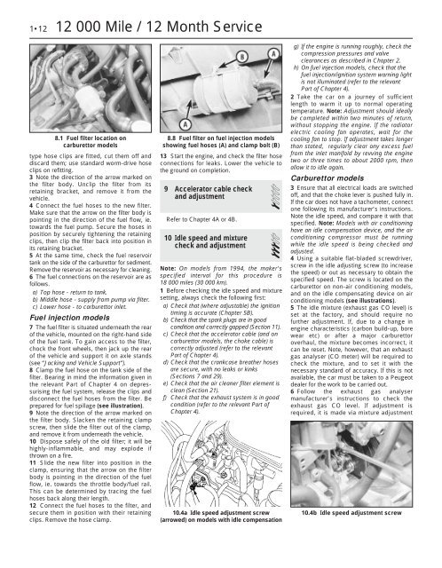
1•12 12 000 Mile / 12 Month Service<br />
8.1 Fuel filter location on<br />
carburettor models<br />
type hose clips are fitted, cut them off <strong>and</strong><br />
discard them; use st<strong>and</strong>ard worm-drive hose<br />
clips on refitting.<br />
3 Note the direction of the arrow marked on<br />
the filter body. Unclip the filter from its<br />
retaining bracket, <strong>and</strong> remove it from the<br />
vehicle.<br />
4 Connect the fuel hoses to the new filter.<br />
Make sure that the arrow on the filter body is<br />
pointing in the direction of the fuel flow, ie.<br />
towards the fuel pump. Secure the hoses in<br />
position by securely tightening the retaining<br />
clips, then clip the filter back into position in<br />
its retaining bracket.<br />
5 At the same time, check the fuel reservoir<br />
tank on the side of the carburettor for sediment.<br />
Remove the reservoir as necessary for cleaning.<br />
6 The fuel connections on the reservoir are as<br />
follows.<br />
a) Top hose - return to tank.<br />
b) Middle hose - supply from pump via filter.<br />
c) Lower hose - to carburettor inlet.<br />
Fuel injection models<br />
7 The fuel filter is situated underneath the rear<br />
of the vehicle, mounted on the right-h<strong>and</strong> side<br />
of the fuel tank. To gain access to the filter,<br />
chock the front wheels, then jack up the rear<br />
of the vehicle <strong>and</strong> support it on axle st<strong>and</strong>s<br />
(see “Jacking <strong>and</strong> Vehicle Support”).<br />
8 Clamp the fuel hose on the tank side of the<br />
filter. Bearing in mind the information given in<br />
the relevant Part of <strong>Chapter</strong> 4 on depressurising<br />
the fuel system, release the clips <strong>and</strong><br />
disconnect the fuel hoses from the filter. Be<br />
prepared for fuel spillage (see illustration).<br />
9 Note the direction of the arrow marked on<br />
the filter body. Slacken the retaining clamp<br />
screw, then slide the filter out of the clamp,<br />
<strong>and</strong> remove it from underneath the vehicle.<br />
10 Dispose safely of the old filter; it will be<br />
highly-inflammable, <strong>and</strong> may explode if<br />
thrown on a fire.<br />
11 Slide the new filter into position in the<br />
clamp, ensuring that the arrow on the filter<br />
body is pointing in the direction of the fuel<br />
flow, ie. towards the throttle body/fuel rail.<br />
This can be determined by tracing the fuel<br />
hoses back along their length.<br />
12 Connect the fuel hoses to the filter, <strong>and</strong><br />
secure them in position with their retaining<br />
clips. Remove the hose clamp.<br />
8.8 Fuel filter on fuel injection models<br />
showing fuel hoses (A) <strong>and</strong> clamp bolt (B)<br />
13 Start the engine, <strong>and</strong> check the filter hose<br />
connections for leaks. Lower the vehicle to<br />
the ground on completion.<br />
9 Accelerator cable check<br />
<strong>and</strong> adjustment 1<br />
Refer to <strong>Chapter</strong> 4A or 4B.<br />
10 Idle speed <strong>and</strong> mixture<br />
check <strong>and</strong> adjustment 3<br />
Note: On models from 1994, the maker’s<br />
specified interval for this procedure is<br />
18 000 miles (30 000 km).<br />
1 Before checking the idle speed <strong>and</strong> mixture<br />
setting, always check the following first:<br />
a) Check that (where adjustable) the ignition<br />
timing is accurate (<strong>Chapter</strong> 5B).<br />
b) Check that the spark plugs are in good<br />
condition <strong>and</strong> correctly gapped (Section 11).<br />
c) Check that the accelerator cable (<strong>and</strong> on<br />
carburettor models, the choke cable) is<br />
correctly adjusted (refer to the relevant<br />
Part of <strong>Chapter</strong> 4).<br />
d) Check that the crankcase breather hoses<br />
are secure, with no leaks or kinks<br />
(Sections 7 <strong>and</strong> 29).<br />
e) Check that the air cleaner filter element is<br />
clean (Section 21).<br />
f) Check that the exhaust system is in good<br />
condition (refer to the relevant Part of<br />
<strong>Chapter</strong> 4).<br />
10.4a Idle speed adjustment screw<br />
(arrowed) on models with idle compensation<br />
g) If the engine is running roughly, check the<br />
compression pressures <strong>and</strong> valve<br />
clearances as described in <strong>Chapter</strong> 2.<br />
h) On fuel injection models, check that the<br />
fuel injection/ignition system warning light<br />
is not illuminated (refer to the relevant<br />
Part of <strong>Chapter</strong> 4).<br />
2 Take the car on a journey of sufficient<br />
length to warm it up to normal operating<br />
temperature. Note: Adjustment should ideally<br />
be completed within two minutes of return,<br />
without stopping the engine. If the radiator<br />
electric cooling fan operates, wait for the<br />
cooling fan to stop. If adjustment takes longer<br />
than stated, regularly clear any excess fuel<br />
from the inlet manifold by revving the engine<br />
two or three times to about 2000 rpm, then<br />
allow it to idle again.<br />
Carburettor models<br />
3 Ensure that all electrical loads are switched<br />
off, <strong>and</strong> that the choke lever is pushed fully in.<br />
If the car does not have a tachometer, connect<br />
one following its manufacturer’s instructions.<br />
Note the idle speed, <strong>and</strong> compare it with that<br />
specified. Note: Models with air conditioning<br />
have an idle compensation device, <strong>and</strong> the air<br />
conditioning compressor must be running<br />
while the idle speed is being checked <strong>and</strong><br />
adjusted.<br />
4 Using a suitable flat-bladed screwdriver,<br />
screw in the idle adjusting screw (to increase<br />
the speed) or out as necessary to obtain the<br />
specified speed. The screw is located on the<br />
carburettor on non-air conditioning models,<br />
<strong>and</strong> on the idle compensating device on air<br />
conditioning models (see illustrations).<br />
5 The idle mixture (exhaust gas CO level) is<br />
set at the factory, <strong>and</strong> should require no<br />
further adjustment. If, due to a change in<br />
engine characteristics (carbon build-up, bore<br />
wear etc) or after a major carburettor<br />
overhaul, the mixture becomes incorrect, it<br />
can be reset. Note, however, that an exhaust<br />
gas analyser (CO meter) will be required to<br />
check the mixture, <strong>and</strong> to set it with the<br />
necessary st<strong>and</strong>ard of accuracy. If this is not<br />
available, the car must be taken to a Peugeot<br />
dealer for the work to be carried out.<br />
6 Follow the exhaust gas analyser<br />
manufacturer’s instructions to check the<br />
exhaust gas CO level. If adjustment is<br />
required, it is made via mixture adjustment<br />
10.4b Idle speed adjustment screw