Chapter 1 Routine maintenance and servicing
Chapter 1 Routine maintenance and servicing
Chapter 1 Routine maintenance and servicing

Create successful ePaper yourself
Turn your PDF publications into a flip-book with our unique Google optimized e-Paper software.
24 000 Mile / 2 Year Service 1•19<br />
emerging from the highest bleed screw in the<br />
cooling system <strong>and</strong> all bleed screws are<br />
securely tightened. Keep the “header tank”<br />
full during this procedure.<br />
24 Once all the bleed screws are securely<br />
tightened, remove the “header tank” <strong>and</strong> refit<br />
the expansion tank cap.<br />
25 Start the engine, <strong>and</strong> run it at 1500 rpm.<br />
Maintain this engine speed until the radiator<br />
cooling fan has cut in <strong>and</strong> out three times.<br />
26 Allow the engine to run at idle speed for a<br />
few minutes.<br />
27 Stop the engine, <strong>and</strong> wait for at least ten<br />
minutes.<br />
28 Place a large wad of rag around the<br />
expansion tank cap, <strong>and</strong> around your h<strong>and</strong>,<br />
then carefully remove the expansion tank cap.<br />
Turn the cap anti-clockwise until it reaches<br />
the first stop. Wait until any pressure<br />
remaining in the system is released, then push<br />
the cap down, turn it anti-clockwise to the<br />
second stop, <strong>and</strong> lift it off.<br />
Warning: Take precautions<br />
against scalding, as the cooling<br />
system will be hot.<br />
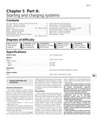
21.1 On TU models disconnect the hoses<br />
from the front of the duct . . .<br />
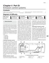
21.2a . . . then release the air cleaner lid<br />
retaining clips, <strong>and</strong> the duct clip . . .<br />
29 Check the coolant level, <strong>and</strong> if necessary<br />
top-up the expansion tank to just above the<br />
“MAXI” level mark (see “Weekly checks”).<br />
30 Refit the expansion tank cap.<br />
Antifreeze mixture<br />
31 The antifreeze should always be renewed<br />
at the specified intervals. This is necessary<br />
not only to maintain the antifreeze properties,<br />
but also to prevent corrosion which would<br />
otherwise occur as the corrosion inhibitors<br />
become progressively less effective.<br />
32 Always use an ethylene-glycol based<br />
antifreeze which is suitable for use in mixedmetal<br />
cooling systems. The quantity of<br />
antifreeze <strong>and</strong> levels of protection are<br />
indicated in the Specifications.<br />
33 Before adding antifreeze, the cooling<br />
system should be completely drained,<br />
preferably flushed, <strong>and</strong> all hoses checked for<br />
condition <strong>and</strong> security.<br />
34 After filling with antifreeze, a label should<br />
be attached to the expansion tank, stating the<br />
type <strong>and</strong> concentration of antifreeze used,<br />
<strong>and</strong> the date installed. Any subsequent<br />
topping-up should be made with the same<br />
type <strong>and</strong> concentration of antifreeze.<br />
35 Do not use engine antifreeze in the<br />
windscreen/tailgate washer system, as it will<br />
cause damage to the vehicle paintwork. A<br />
screenwash additive should be added to the<br />
washer system in the quantities stated on the<br />
bottle.<br />
21.2b . . . <strong>and</strong> remove the duct, positioning<br />
it clear of the air cleaner housing<br />
TU models<br />
1 Slacken the retaining clips (where fitted),<br />
<strong>and</strong> disconnect the vacuum hose <strong>and</strong><br />
breather hose from the front of the air cleaner<br />
housing-to-carburettor/throttle body duct<br />
(see illustration). Where the crimped-type<br />
Peugeot hose clips are fitted, cut the clips <strong>and</strong><br />
discard them; use st<strong>and</strong>ard worm-drive hose<br />
clips on refitting.<br />
2 Slacken the retaining clip securing the duct<br />
to the carburettor/throttle body. Release the<br />
retaining clips securing the lid to the top of the<br />
air cleaner housing. Lift the duct <strong>and</strong> air<br />
cleaner lid assembly away, <strong>and</strong> position it<br />
clear of the air cleaner housing (see<br />
illustrations).<br />
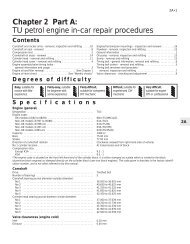
3 Lift the air cleaner element out of the<br />
housing (see illustration).<br />
4 Fit the new element into the housing, <strong>and</strong><br />
secure it in position with the retaining clips.<br />
5 Refit the sealing ring to the top of the filter<br />
21.3 Removing the air cleaner element<br />
on TU models<br />
(where fitted), <strong>and</strong> refit the air cleaner-tocarburettor/throttle<br />
body duct. Ensure that the<br />
duct <strong>and</strong> its sealing rings are correctly seated,<br />
<strong>and</strong> securely tighten the retaining clips.<br />
6 Reconnect the vacuum <strong>and</strong> breather hoses<br />
to the duct, <strong>and</strong> secure them in position with<br />
the retaining clips (where fitted).<br />
XU models<br />
(except XU10J4 16-valve)<br />
with side-mounted air cleaner<br />
7 Disconnect the air duct from the filter<br />
housing cover to the carburettor/airflow meter<br />
at the filter housing end (see illustration).<br />
8 Release the clips <strong>and</strong> lift off the air cleaner<br />
top cover (see illustration).<br />
9 Withdraw the filter element from the air<br />
cleaner body (see illustration).<br />
10 Fit the new element in position in the air<br />
cleaner body making sure that it is the right<br />
way round.<br />
1<br />
21 Air filter renewal<br />
2<br />
Note: On models from 1994, the maker’s<br />
specified interval for this procedure is<br />
36 000 miles (60 000 km).<br />
21.7 Air filter housing cover located in the<br />
left-h<strong>and</strong> front of the engine compartment<br />
21.8 Lifting off the top cover