Areva EPR
Areva EPR
Areva EPR

You also want an ePaper? Increase the reach of your titles
YUMPU automatically turns print PDFs into web optimized ePapers that Google loves.
<strong>EPR</strong>
Readers accustomed to British units can use<br />
the following table to convert the main units<br />
from the International Metric System.<br />
1 meter (m) = 3.2808 feet<br />
= 39.370 inches<br />
1 square meter (m 2 ) = 10.764 square feet<br />
1 cubic meter (m 3 ) = 264.17 US gallons<br />
1 kilogram (kg) = 2.2046 pounds<br />
1 tonne (t) = 1.1023 short ton<br />
1 bar = 14.5 psi<br />
> Conversion of temperature (°C into °F)<br />
Temp. °C x 9/5 + 32 = Temp. °F<br />
> All pressures are expressed in absolute bar.
• EDF (Electricité de France), and the major German utilities<br />
now merged to become E.ON, EnBW and RWE Power,<br />
• the safety authorities from both countries to harmonize<br />
safety regulations.<br />
The <strong>EPR</strong> design takes into account the expectations of utilities<br />
as stated by the “European Utility Requirements” (EUR)<br />
and the “Utility Requirements Document” (URD) issued by<br />
the US Electric Power Research Institute (<strong>EPR</strong>I). It complies<br />
with the recommendations (1993) and positions on<br />
major issues (1995) that the French and German safety<br />
authorities jointly set up. The technical guidelines covering the<br />
<strong>EPR</strong> design were validated in October 2000 by the French<br />
standing group of experts in charge of reactor safety (“Groupe<br />
Permanent Réacteurs” which is the advisory committee for<br />
reactor safety to the French safety authority) supported by<br />
German experts.<br />
On September 28, 2004, the French safety authority, on<br />
behalf of the French government, officially stated that the<br />
<strong>EPR</strong> safety options comply with the safety enhancement<br />
objectives established for new nuclear reactors.<br />
Continuity in technology<br />
The N4 and KONVOI reactors are children of the earlier<br />
Framatome and Siemens KWU generation reactors which<br />
are themselves derivative of standard US type PWRs, first<br />
implemented in the US, then refined and expanded upon<br />
by Framatome and Siemens KWU. The <strong>EPR</strong> is the direct<br />
descendant of the well proven N4 and KONVOI reactors,<br />
guaranteeing a fully mastered technology. As a result, risks<br />
linked to design, licensing, construction and operation of<br />
the <strong>EPR</strong> are minimized, providing a unique certainty to <strong>EPR</strong><br />
customers.<br />
Operator expertise acquired through the operation of nuclear<br />
power plants using the same technology as the <strong>EPR</strong> is maintained<br />
and its value is increased.<br />
Another major advantage is that the existing industrial<br />
capacities for design, engineering, equipment manufacturing,<br />
nuclear power plant construction and maintenance<br />
– including capacities resulting from previous technology<br />
transfers – can be easily deployed and utilized to carry out<br />
new nuclear plant projects based on <strong>EPR</strong> technology.<br />
† The <strong>EPR</strong> relies on a sound and proven<br />
technology.<br />
† It complies with safety authorities<br />
requirements for new nuclear plants.<br />
† Design and licensing, construction<br />
and commissioning, operability and maintainability<br />
of <strong>EPR</strong> units benefit from Framatome<br />
ANP long lasting and worldwide experience<br />
and expertise. Therefore, <strong>EPR</strong> customers<br />
uniquely minimize their technical risks and<br />
associated financial impacts.<br />
Enhanced economic competitiveness<br />
The next generation of nuclear power plants will have to be<br />
even more competitive to successfully cope with deregulated<br />
electricity markets.<br />
Thanks to an early focus on economic competitiveness during<br />
its design process, the <strong>EPR</strong> offers significantly reduced<br />
power generation costs. They are estimated to be 10%<br />
lower than those of the most modern nuclear units currently<br />
in operation, and more than 20% less than those of the<br />
largest high-efficiency advanced combined-cycle gas plants<br />
currently under development (taking into account a gas price<br />
in the US$* 3.5 per MBtu range). The advantage over fossil<br />
plants is even more pronounced when the “external costs”<br />
(such as costs related to the damage to environment and<br />
human health) are taken into account.<br />
* In 2001 US$.<br />
This high level of competitiveness is achieved through:<br />
† a unit power in the 1,600 MWe range<br />
(the highest unit power to date), providing<br />
an attractive cost of the installed kWe,<br />
† a 36-37% overall efficiency depending<br />
on site conditions (presently the highest<br />
value ever for water reactors),<br />
† a shortened construction time relying on<br />
experience feedback and continuous<br />
improvement of construction methodology<br />
and tasks sequencing,<br />
† a design for a 60-year service life,<br />
† an enhanced and more flexible fuel utilization,<br />
† an availability factor up to 92%, on average,<br />
during the entire service life<br />
of the plant, obtained through long irradiation<br />
cycles, shorter refueling outages and<br />
in-operation maintenance.<br />
Significant advances<br />
for sustainable development<br />
The <strong>EPR</strong>, due to its optimized core design and higher overall<br />
efficiency compared to the reactors in operation today,<br />
also offers many significant advantages in favor of sustainable<br />
development, typically:<br />
• 17% saving on Uranium consumption per<br />
produced MWh,<br />
• 15% reduction on long-lived actinides<br />
generation per MWh,<br />
• 14% gain on the “electricity generation”<br />
versus “thermal release” ratio (compared<br />
to 1,000 MWe-class reactors),<br />
• great flexibility to use MOX (mixed<br />
UO 2 -PuO 2 ) fuel.<br />
I 03
FOREWORD<br />
The <strong>EPR</strong>’s key assets<br />
to support a strategic choice<br />
An evolutionary, safe<br />
and innovative design<br />
The <strong>EPR</strong> is a 1,600 MWe class PWR. Its evolutionary design<br />
is based on experience from several thousand reactor - years<br />
of operation of Light Water Reactors worldwide, primarily<br />
those incorporating the most recent technologies: the N4 and<br />
KONVOI reactors currently in operation in France and<br />
Germany respectively. The <strong>EPR</strong> design integrates the results<br />
of decades of research and development programs, in particular<br />
those carried out by the CEA (French Atomic Energy<br />
Commission) and the German Karlsruhe research center.<br />
Through its N4 and KONVOI filiation, the <strong>EPR</strong> totally benefits<br />
from the uninterrupted evolutionary and innovation<br />
process which has continuously supported the development<br />
of the PWR since its introduction in the Western marketplace<br />
in the mid-fifties.<br />
Offering a significantly enhanced level of safety, the <strong>EPR</strong><br />
features major innovations, especially in further preventing core<br />
meltdown and mitigating its potential consequences. The<br />
<strong>EPR</strong> design also benefits from outstanding resistance to<br />
external hazards, including military or large commercial airplane<br />
crash and earthquake. Together, the <strong>EPR</strong> operating and<br />
safety systems provide progressive responses commensurate<br />
with any abnormal occurrences.<br />
Thanks to a number of technological advances, the <strong>EPR</strong> is<br />
at the forefront of nuclear power plants design. Significant<br />
progress has been incorporated into its main features:<br />
• the reactor core and its flexibility in terms of fuel management,<br />
• the reactor protection system,<br />
• the instrumentation and control (I & C) system, the operator<br />
friendly man-machine interface and fully computerized<br />
control room of the plant,<br />
• the large components such as the reactor pressure vessel<br />
and its internal structures, steam generators and primary<br />
coolant pumps.<br />
These innovations contribute to the high level of performance,<br />
efficiency, operability and therefore economic competitiveness<br />
offered by the <strong>EPR</strong> to fully satisfy customers’<br />
expectations for their future nuclear power plants.<br />
The straightforward answer to utilities’ and<br />
safety authorities’ requirements for new<br />
nuclear power plants<br />
The French-German cooperation set up to develop the <strong>EPR</strong><br />
brought together, from the start of the project:<br />
• power plant vendors, Framatome and Siemens KWU<br />
(whose nuclear activities have since been merged to form<br />
Framatome ANP, now an AREVA and Siemens company),<br />
> Building on Experience<br />
Enhanced safety level and competitiveness<br />
Evolutionary<br />
development<br />
keeps references<br />
N4<br />
Solid basis of experience<br />
with outstanding performance<br />
KONVOI<br />
02 I
FOREWORD<br />
Security of energy supply and energy cost stability in the long<br />
term, plus the efforts to combat the greenhouse effect and<br />
potential global warming, argue in favor of a greater diversity<br />
in sources of energy supplies. Against this background<br />
nuclear power, which is more and more economically competitive,<br />
safe, reliable and environment friendly, has a vital role to play.<br />
A world expert in energy, AREVA creates and offers solutions<br />
to generate, transmit and distribute electricity; its businesses<br />
cover on a long-term basis every sector in the use of nuclear<br />
power to support electricity needs: front end (Uranium ore<br />
mining and conversion, Uranium enrichment, fuel fabrication),<br />
reactor design and construction, reactor services, back end<br />
of the fuel cycle, transmission and distribution from the generator<br />
to the large end-users.<br />
The <strong>EPR</strong> is a large advanced evolutionary reactor of the<br />
Pressurized Water Reactor (PWR) type offered by AREVA<br />
to satisfy electricity companies’ needs for a new generation<br />
of nuclear power plants even more competitive and safer<br />
while contributing to sustainable development.<br />
I 01
INTRODUCTION<br />
In a nuclear power plant, the reactor is the part of the facility in which the heat,<br />
necessary to produce steam, is generated by fission of atom nuclei.<br />
The produced steam drives a turbine generator, which generates electricity.<br />
The nuclear steam supply system is therefore the counterpart of coal, gas or oil-fired<br />
boilers of fossil-fuelled plants.<br />
In a Pressurized Water Reactor (PWR)<br />
like the <strong>EPR</strong>, ordinary water is utilized<br />
to remove the heat formed inside<br />
the reactor core by the nuclear fission<br />
phenomenon. This water also slows<br />
down (or moderates) neutrons<br />
(constituents of atom nuclei that are<br />
released in the nuclear fission process).<br />
Slowing down neutrons is necessary<br />
to keep the chain reaction going<br />
(neutrons have to be moderated<br />
to be able to break down<br />
the fissile atom nuclei).<br />
The heat produced inside the reactor<br />
core is transferred to the turbine<br />
through the steam generators.<br />
From the reactor core coolant circuit<br />
(primary circuit) to the steam circuit<br />
used to feed the turbine (secondary<br />
circuit), only heat is transferred and<br />
there is no water exchange.<br />
The primary water is pumped<br />
through the reactor core and the<br />
primary side of the steam generators,<br />
in four parallel closed loops, by electric<br />
motor-powered coolant pumps.<br />
Each loop is equipped with a steam<br />
generator and a coolant pump.<br />
The reactor operating pressure<br />
and temperature are such that the<br />
cooling water does not evaporate<br />
and remains in the liquid state,<br />
which intensifies its cooling efficiency.<br />
A pressurizer controls the pressure;<br />
it is connected to one of the loops.<br />
Pressurizer<br />
Primary<br />
Pump<br />
Steam Generator<br />
Control<br />
Rod Drive<br />
Mechanism<br />
The feedwater entering the secondary<br />
side of the steam generators absorbs<br />
the heat transferred from the primary<br />
side and evaporates to produce<br />
saturated steam. The steam is dried in<br />
the steam generators then routed to the<br />
turbine to drive it. Then, the steam is<br />
condensed and it returns as feedwater<br />
to the steam generators.<br />
The generator, driven by the turbine,<br />
generates electricity.<br />
Transformer<br />
† The following chapters will provide<br />
detailed explanation about the<br />
description and operation of PWR<br />
nuclear power stations based on<br />
the <strong>EPR</strong> reactor.<br />
Reactor<br />
Core<br />
Vessel<br />
Feedwater<br />
Pump<br />
Reheater<br />
Cooling<br />
Water<br />
Generator<br />
Condenser<br />
High Voltage<br />
Electrical Lines<br />
Primary system<br />
Secondary system:<br />
– Steam<br />
– Water<br />
04 I<br />
I 05
TABLE OF CONTENTS<br />
page 08 page 44<br />
page 52 page 54<br />
<strong>EPR</strong> NUCLEAR ISLAND<br />
><strong>EPR</strong> LAYOUT<br />
>PRIMARY SYSTEM<br />
>REACTOR CORE<br />
>FUEL ASSEMBLIES<br />
>CONTROL ASSEMBLIES<br />
>REACTOR PRESSURE VESSEL<br />
AND INTERNAL STRUCTURES<br />
>STEAM GENERATORS<br />
SAFETY<br />
>NUCLEAR SAFETY<br />
Three protective barriers<br />
Defense in depth<br />
><strong>EPR</strong> SAFETY<br />
Design choices for reducing<br />
the probability of accidents<br />
liable to cause core melt<br />
Design choices for limiting the<br />
consequences of a severe accident<br />
<strong>EPR</strong> CONSTRUCTION<br />
><strong>EPR</strong> CONSTRUCTION TIME SCHEDULE<br />
Design features<br />
Construction and erection methods<br />
Commissioning tests<br />
PLANT OPERATION,<br />
MAINTENANCE & SERVICES<br />
A 92% availability factor<br />
over the entire plant life<br />
A high level of operational<br />
maneuverability<br />
An enhanced radiological protection<br />
Plant services<br />
Continuously improving service<br />
to customers<br />
page 58<br />
CONCLUDING REMARKS<br />
>REACTOR COOLANT PUMPS<br />
AND MAIN COOLANT LINES<br />
>PRESSURIZER<br />
>SYSTEMS<br />
Chemical and volume control<br />
Safety injection /<br />
residual heat removal<br />
In-containment refueling<br />
water storage tank<br />
Emergency feedwater<br />
Other safety systems<br />
Component Cooling Water<br />
Essential Service Water<br />
Other systems<br />
Power supply<br />
Fuel handling and storage<br />
>INSTRUMENTATION<br />
& CONTROL SYSTEM<br />
<strong>EPR</strong> I & C overall architecture<br />
Role of the I & C systems<br />
06 I<br />
I 07
<strong>EPR</strong> NUCLEAR ISLAND<br />
Civaux nuclear power plant, France<br />
(N4, 1,500 MWe)<br />
I 09
<strong>EPR</strong> LAYOUT page 10<br />
>PRIMARY SYSTEM page 14<br />
>REACTOR CORE page 16<br />
>FUEL ASSEMBLIES page 18<br />
> CONTROL ASSEMBLIES page 20<br />
>REACTOR PRESSURE VESSEL<br />
AND INTERNAL STRUCTURES page 22<br />
> STEAM GENERATORS page 26<br />
>REACTOR COOLANT PUMPS<br />
& MAIN COOLANT LINES page 28<br />
>PRESSURIZER page 32<br />
>SYSTEMS page 34<br />
CHEMICAL AND VOLUME CONTROL page 34<br />
SAFETY INJECTION /<br />
RESIDUAL HEAT REMOVAL page 35<br />
IN-CONTAINMENT REFUELING WATER<br />
STORAGE TANK page 36<br />
EMERGENCY FEEDWATER page 36<br />
OTHER SAFETY SYSTEMS page 37<br />
COMPONENT COOLING WATER page 37<br />
ESSENTIAL SERVICE WATER page 37<br />
OTHER SYSTEMS page 37<br />
POWER SUPPLY page 38<br />
FUEL HANDLING AND STORAGE page 39<br />
>INSTRUMENTATION<br />
& CONTROL SYSTEM page 40<br />
<strong>EPR</strong> I & C OVERALL ARCHITECTURE page 40<br />
ROLE OF THE I & C SYSTEMS page 41<br />
08 I
■ <strong>EPR</strong> NUCLEAR ISLAND<br />
<strong>EPR</strong> LAYOUT<br />
7<br />
3<br />
4<br />
1<br />
3<br />
3<br />
2<br />
3<br />
5<br />
4<br />
6<br />
1 Reactor Building<br />
The Reactor Building located in the center of the Nuclear Island houses<br />
the main equipment of the Nuclear Steam Supply System (NSSS)<br />
and the In-Containment Refueling Water Storage Tank (IRWST). Its<br />
main function is to ensure protection of the environment against internal<br />
and external hazards consequences under all circumstances. It<br />
consists of a cylindrical pre-stressed inner containment with a metallic<br />
liner surrounded by an outer reinforced concrete shell.<br />
The main steam and feedwater valves are housed in dedicated<br />
reinforced concrete compartments adjacent to the Reactor Building.<br />
The primary system arrangement is characterized by:<br />
• pressurizer located in a separate area,<br />
• concrete walls between the loops and between the hot and cold<br />
legs of each loop,<br />
• concrete wall (secondary shield wall) around the primary system<br />
to protect the containment from missiles and to reduce the spread<br />
of radiation from the primary system to the surrounding areas.<br />
2 Fuel Building<br />
The Fuel Building, located on the same common basemat as the<br />
Reactor Building and the Safeguard Buildings, houses the fresh fuel,<br />
the spent fuel in an interim fuel storage pool and associated handling<br />
equipment. Operating compartments and passageways, equipment<br />
compartments, valve compartments and the connecting pipe ducts<br />
are separated within the building. Areas of high activity are separated<br />
from areas of low activity by means of shielding facilities. The<br />
mechanical floor houses the fuel pool cooling system, the emergency<br />
boration system, and the chemical and volume control system. The<br />
redundant trains of these systems are physically separated by a wall<br />
into two building parts.<br />
3 The Safeguard Buildings<br />
The four Safeguard Buildings house the safeguard systems such as<br />
the Safety Injection System and the Emergency Feedwater System,<br />
and their support systems. The four different trains of these safeguard<br />
systems are housed in four separate divisions, each located in one<br />
of the four Safeguard Buildings.<br />
The Low Head Safety Injection System is combined with the<br />
Residual Heat Removal System. They are arranged at the inner areas<br />
in the radiologically controlled areas, whereas the corresponding<br />
Component Cooling and Emergency Feedwater Systems are<br />
installed at the outer areas in the classified non-controlled areas.<br />
The Main Control Room is located in one of the Safeguard Buildings.<br />
4 Diesel Buildings<br />
The two Diesel Buildings shelter the four emergency Diesel<br />
generators and their support systems, and supply electricity to the<br />
safeguard trains in the event of a complete loss of electrical power.<br />
The physical separation of these two buildings provides additional<br />
protection.<br />
10 I
Water outfall<br />
Switchyard<br />
Water intake<br />
Nuclear Island<br />
Turbine Island<br />
Balance of Plant<br />
Quay<br />
5 Nuclear Auxiliary Building<br />
6 Waste Building<br />
Part of the Nuclear Auxiliary Building (NAB) is designed as a<br />
radiological non-controlled area in which parts of the Operational<br />
Chilled Water System are located. Special laboratories for sampling<br />
systems are located at the lowest level. The maintenance area and<br />
some setdown areas used during the refueling phase are arranged<br />
on the highest level. All air-exhausts from the radiological controlled<br />
areas are routed, collected and controlled within the Nuclear Auxiliary<br />
Building prior to release through the stack.<br />
The Waste Building is used to collect, store and treat liquid and solid<br />
radioactive waste.<br />
7 Turbine Building<br />
The Turbine Building houses all the main components of the steamcondensate-feedwater<br />
cycle. It contains, in particular, the turbine,<br />
the generator set, the condenser and their auxiliary systems.<br />
I 11
■ <strong>EPR</strong> NUCLEAR ISLAND<br />
Nuclear Island building arrangement<br />
REACTOR BUILDING<br />
+ 57.50<br />
+ 33.10<br />
FUEL BUILDING<br />
+29.00m<br />
SPENT FUEL<br />
MAST BRIGDE<br />
+19.50<br />
+38.60<br />
+33.80<br />
+34.45<br />
+19.65<br />
STORAGE AREA<br />
FOR RPV –<br />
CLOSURE H.<br />
+28.50<br />
+24.10<br />
+19.50<br />
SUPPLY AIR<br />
INLET<br />
SAFEGUARD BUILDING<br />
DIVISION 2<br />
IODINE FILT./<br />
AIR COND. MCR<br />
+ 30.50<br />
AIR DUCT<br />
SMOKE<br />
EXTRAC.<br />
SYSTEM<br />
EXH.<br />
AIR<br />
+ 26.70<br />
FUEL STORAGE POOL<br />
TRANSFER STATION<br />
+13.80<br />
+5.15<br />
STORAGE<br />
POOL<br />
+10.00<br />
+6.30<br />
INCORE<br />
INSTRUMENT.<br />
+14.97<br />
SPRAY<br />
VALVES<br />
+9.80<br />
+7.44<br />
+7.44 SPRAY<br />
+6.95<br />
LINES<br />
+4.64 +5.64<br />
SG – BLOW DOWN<br />
+13.80<br />
+8.70<br />
+5.15<br />
SIC S<br />
I & C<br />
TECHNICAL<br />
MAIN CONTROL ROOM SUPPORT<br />
CENTER<br />
CABLE<br />
BATTERIES<br />
FLOOR<br />
220 V<br />
CABINETS<br />
SWITCHGEARS<br />
CABLE<br />
CABLE<br />
FLOOR<br />
FLOOR<br />
0.00<br />
– 9.60<br />
EBS–TANK<br />
EBS PUMP<br />
PIPE<br />
DUCT<br />
PIPE<br />
VALVE VALVE DUCT<br />
ROOM ROOM<br />
PIPE<br />
CVCS PUMP DUCT<br />
SUMP<br />
–4.35<br />
+1.50<br />
–2.30<br />
CVCS<br />
CVCS<br />
SPREADING<br />
AREA<br />
SYSTEM<br />
+1.50<br />
–2.30<br />
–5.35<br />
IRWST<br />
–7.80<br />
–6.15<br />
+2.60<br />
PERSONNEL<br />
+1.50AIR LOCK<br />
LHSI/<br />
SIS/RHR<br />
VALVE<br />
RHR–HX<br />
ROOM<br />
LHSI<br />
KT/<br />
PUMP<br />
RPE<br />
CABLE–SHAFT<br />
EFWS<br />
WATER TANK<br />
EFWS PUMP<br />
0.00<br />
– 8.60<br />
–11.70<br />
0 246810 20m<br />
† The <strong>EPR</strong> layout offers exceptional and<br />
unique resistance to external hazards,<br />
especially earthquake and airplane crash.<br />
• To withstand major earthquake, the entire<br />
Nuclear Island stands on a single thick<br />
reinforced concrete basemat. Building<br />
height has been minimized and heavy<br />
components and water tanks are located<br />
at the lowest possible level.<br />
• To withstand large airplane crash, the<br />
Reactor Building, Spent Fuel Building<br />
and two of the four Safeguard Buildings<br />
are protected by an outer shell made<br />
of reinforced concrete. The other<br />
two Safeguard Buildings are protected<br />
by a geographical separation. Similarly,<br />
the Diesel generators are located<br />
in two geographically separate buildings<br />
to avoid common failures.<br />
The outer shell (in blue in the image) protects the Reactor Building, the Spent Fuel Building<br />
and two of the four Safeguard Buildings including the control room.<br />
12 I
2 t<br />
+8.50m<br />
1<br />
2<br />
3<br />
4<br />
5<br />
6<br />
1<br />
2<br />
8<br />
6<br />
1<br />
5<br />
2<br />
4<br />
3<br />
6<br />
4<br />
5<br />
4<br />
1<br />
3<br />
1<br />
5<br />
2<br />
3<br />
2<br />
6<br />
5<br />
4<br />
10<br />
9<br />
6<br />
2<br />
1<br />
2<br />
5<br />
12<br />
1<br />
11<br />
2<br />
10<br />
3<br />
9<br />
8<br />
7<br />
4<br />
3<br />
6<br />
10<br />
9<br />
2<br />
8<br />
7<br />
4<br />
6<br />
5<br />
6<br />
1<br />
5<br />
2<br />
4<br />
3<br />
2<br />
1<br />
+12.76m<br />
2<br />
1<br />
8<br />
1<br />
7<br />
6<br />
5<br />
4<br />
4<br />
3<br />
2<br />
3<br />
1<br />
2<br />
Miscellaneous plan view<br />
SAFEGUARD<br />
BUILDING<br />
DIVISION 2<br />
SAFEGUARD<br />
BUILDING<br />
DIVISION 3<br />
I & C SERVICE CENTER<br />
TECHNICAL SUPPORT CENTER<br />
DOCUMENTATION ROOM<br />
SHIFT OFFICE<br />
TOILETS<br />
KITCHEN<br />
SURVEIL.<br />
SYSTEM<br />
MAIN CONTROL ROOM<br />
TAGGING ROOM<br />
MCR<br />
ENTRANCE<br />
HATCH<br />
TOOLS SPARE<br />
PARTS<br />
ACCESS<br />
CONTROL<br />
ROOM<br />
SICS 1/COMPUTER ROOM 1 SICS 2 /COMPUTER ROOM 2<br />
SAFEGUARD<br />
BUILDING<br />
DIVISION 1<br />
+14.97 +14.97<br />
INCORE<br />
INSTRUMEN.<br />
+13.80<br />
SAFEGUARD<br />
BUILDING<br />
DIVISION 4<br />
ACCU<br />
ACCU<br />
ANTEROOM<br />
MHSI PUMP<br />
+13.80<br />
+11.10<br />
+12.36<br />
PRESSU-<br />
RIZER<br />
+12.36<br />
+13.80<br />
3 1<br />
SWITCHGEARS<br />
SWITCHGEARS<br />
+11.10<br />
EFWS PUMP<br />
SERVICE CORRIDOR<br />
SUMP<br />
VALVE<br />
LHSI PUMP<br />
+13.80<br />
+13.80<br />
+13.80<br />
+13.80<br />
5 4 3<br />
7 6<br />
10 9<br />
7 8<br />
4 3<br />
5 4<br />
2 1<br />
3 1<br />
CCWS PUMP<br />
CHRS PUMP<br />
AIR<br />
LOCK CHRS<br />
SUMP VALVE<br />
PASSAGEWAY<br />
ACCU<br />
+13.80<br />
+13.80<br />
+11.10<br />
+13.80<br />
STORAGE<br />
POOL<br />
+7.44<br />
+11.10<br />
+13.80<br />
+13.80<br />
ACCU<br />
I&C CABINETS<br />
+8.10<br />
I&C CABINETS<br />
BATTERIES 220 V<br />
IODINE FAN<br />
+13.80<br />
HVAC DISTRIBUTION<br />
TRANSFER PIT<br />
HVAC DISTRIBUTION<br />
PIPE DUCT<br />
VAPOUR<br />
COMPRESSOR<br />
VAPOUR<br />
COMPRESSOR<br />
SERVICE CORRIDOR<br />
+17.30m<br />
IODINE FAN<br />
MONITOR AIR<br />
ACTIVITY<br />
EXHAUST BOOSTER<br />
FANS<br />
+16.70m<br />
+13.80m<br />
LOADING<br />
PIT<br />
+9.70m<br />
+5.10m<br />
+6.30m<br />
KLA/EBA KLA/EBA<br />
FILTERS FAN<br />
DECONT SYSTEM<br />
FOR RCP<br />
VAPOUR<br />
COMPRESSOR<br />
CONDENSER AND<br />
SPENT FUEL STORAGE POOL<br />
GASCOOLER<br />
HEPA FILTERS<br />
+16.70m<br />
VALVE ROOM<br />
BORON<br />
PREPARATION<br />
TANK<br />
DELAY BEDS<br />
HEPA FILTERS<br />
0 246810 20m<br />
FUEL BUILDING<br />
MATERIAL LOCK<br />
NUCLEAR AUXILIARY<br />
BUILDING<br />
† The <strong>EPR</strong> Nuclear Island design has undisputed advantages for operators,<br />
especially where radiation protection and ease of maintenance are concerned.<br />
• The layout is optimized and based on the strict separation of redundant systems.<br />
• The distinction between access-controlled areas containing radioactive<br />
equipment and non-controlled areas significantly contributes to reduce<br />
exposure of the operating personnel.<br />
• Maintenance requirements were systematically taken into account at the earliest<br />
stage of the design. For example, large setdown areas have been designed to<br />
make maintenance operations easier for operating personnel.<br />
I 13
■ <strong>EPR</strong> NUCLEAR ISLAND<br />
PRIMARY SYSTEM<br />
†<br />
PRIMARY SYSTEM CONFIGURATION<br />
The <strong>EPR</strong> primary system is of a well proven 4-loop design.<br />
French 1,300 MWe and 1,500 MWe N4 reactors as well as German<br />
KONVOI reactors are also of 4-loop design.<br />
In each of the four loops, the primary coolant leaving the reactor<br />
pressure vessel through an outlet nozzle goes to a steam generator<br />
– the steam generator transfers heat to the secondary circuit –, then<br />
the coolant goes to a reactor coolant pump before returning to the<br />
reactor pressure vessel through an inlet nozzle. Inside the reactor<br />
pressure vessel, the primary coolant is first guided downward outside<br />
the core periphery, then it is channeled upward through the core,<br />
where it receives heat generated by the nuclear fuel.<br />
A pressurizer, part of the primary system, is connected to one of the<br />
four loops. In normal operation, its main role is to automatically<br />
maintain the primary pressure within a specified range.<br />
The <strong>EPR</strong> main reactor components: reactor pressure vessel,<br />
pressurizer and steam generators feature larger volumes than similar<br />
components from previous designs to provide additional benefit in<br />
terms of operation and safety margins.<br />
The increased free volume in the reactor pressure vessel, between<br />
the nozzles of the reactor coolant lines and the top of the core,<br />
provides a higher water volume above the core and thus additional<br />
margin with regard to the core “dewatering” time in the event of a<br />
postulated loss of coolant accident. Therefore, more time would be<br />
available to counteract such a situation.<br />
This increased volume would also be beneficial in shutdown<br />
conditions in case of loss of the Residual Heat Removal System<br />
function.<br />
Larger water and steam phase volumes in the pressurizer smooth<br />
the response of the plant to normal and abnormal operating<br />
transients allowing extended time to counteract accident situations<br />
and extended equipment lifetime.<br />
The larger volume of the steam generator secondary side results in<br />
increasing the secondary water inventory and the steam volume,<br />
which offers several advantages.<br />
• During normal operation, smooth transients are obtained and thus<br />
the potential for unplanned reactor trips is reduced.<br />
• Regarding the management of steam generator tube rupture<br />
scenarios, the large steam volume, in conjunction with a setpoint of<br />
the safety valves of the steam generators above the safety injection<br />
pressure, prevents liquid release outside the reactor containment.<br />
• Due to the increased mass of secondary side water, in case of an<br />
assumed total loss of the steam generator feedwater supply, the<br />
dry-out time would be at least 30 minutes, sufficient time to recover<br />
a feedwater supply or to decide on other countermeasures.<br />
In addition, the primary system design pressure has been increased<br />
in order to reduce the actuation frequency of the safety valves which<br />
is also an enhancement in terms of safety.<br />
Cattenom, France (4 X 1,300 MWe): inside a reactor building.<br />
14 I
CHARACTERISTICS<br />
DATA<br />
Reactor coolant system<br />
Core thermal power<br />
4,500 MWth<br />
Number of loops 4<br />
Coolant flow per loop 28,330 m 3 /h<br />
Reactor pressure vessel inlet temperature 295.9 °C<br />
Reactor pressure vessel outlet temperature 327.2 °C<br />
Primary side design pressure<br />
176 bar<br />
Primary side operating pressure<br />
155 bar<br />
Secondary side design pressure<br />
100 bar<br />
Saturation pressure at nominal conditions<br />
78 bar<br />
Main steam pressure at hot standby<br />
90 bar<br />
OVERALL FUNCTIONAL REQUIREMENTS<br />
AND FEATURES<br />
Activation of safety systems<br />
Activation of the safety systems, including safety valves, does not<br />
occur prior to reactor trip, which means that best possible use is<br />
made of the depressurizing effect of the reactor trip. This approach<br />
also ensures maximum safety by minimizing the number of valve<br />
activations and the potential for valves sticking open after response.<br />
Preventing reactor trip<br />
Reactor trip is prevented by a fast reactor power cutback to part<br />
load when one of the following events occurs:<br />
• loss of steam generator feedwater pumps, provided at least one<br />
of them remains available,<br />
• turbine trip,<br />
• full load rejection,<br />
• loss of one reactor coolant pump.<br />
† The increased volume of the primary<br />
system is beneficial for smoothing over<br />
many types of transients.<br />
† The primary system design pressure has<br />
been increased to reduce the safety valve<br />
actuation frequency.<br />
† The management of steam generator tube<br />
rupture scenarios prevents any liquid<br />
release outside the reactor containment.<br />
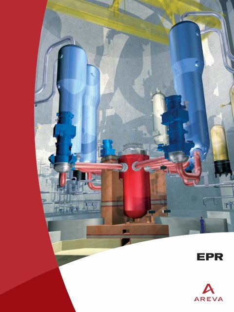
Computer-generated image<br />
of the <strong>EPR</strong> primary system<br />
† The large steam generator secondary<br />
side water inventory increases the time<br />
available to take action in case of<br />
assumed total loss of secondary<br />
feedwater.<br />
I 15
■ <strong>EPR</strong> NUCLEAR ISLAND<br />
REACTOR CORE<br />
†<br />
The reactor core contains the fuel material in which the fission<br />
reaction takes place, releasing energy. The reactor internal<br />
structures serve to physically support this fissile material,<br />
control the fission reaction and channel the coolant.<br />
The core is cooled and moderated by light water at a pressure of<br />
155 bar and a temperature in the range of 300 °C. The coolant<br />
contains soluble Boron as a neutron absorber. The Boron<br />
concentration in the coolant is varied as required to control relatively<br />
slow reactivity changes, including the effects of fuel burnup.<br />
Additional neutron absorbers (Gadolinium), in the form of burnable<br />
absorber-bearing fuel rods, are used to adjust the initial reactivity<br />
and power distribution. Instrumentation is located inside and outside<br />
the core to monitor its nuclear and thermal-hydraulic performance<br />
and to provide input for control functions.<br />
The <strong>EPR</strong> core consists of 241 fuel assemblies. For the first core,<br />
assemblies are split into four groups with different enrichments (two<br />
groups with the highest enrichment, one of them with Gadolinium).<br />
For reload cores, the number and characteristics of the fresh<br />
assemblies depend on the type of fuel management scheme<br />
selected, notably cycle length and type of loading patterns. Fuel<br />
cycle lengths up to 24 months, IN-OUT and OUT-IN fuel<br />
management are possible. The <strong>EPR</strong> is designed for flexible operation<br />
with UO 2 fuel and/or MOX fuel. The main features of the core and its<br />
operating conditions have been selected to obtain not only high<br />
thermal efficiency of the plant and low fuel cycle costs, but also<br />
extended flexibility for different fuel cycle lengths and a high level of<br />
maneuverability.<br />
Core instrumentation<br />
The core power is measured using the ex-core instrumentation, also<br />
utilized to monitor the process to criticality.<br />
The reference instrumentation to monitor the power distribution in<br />
the core is an “aeroball” system. Vanadium balls are periodically<br />
inserted in the core. Their activation level is measured, giving values<br />
of the local neutron flux to construct the three-dimensional power<br />
map of the core.<br />
The fixed in-core instrumentation consists of neutron detectors and<br />
thermocouples to measure the neutron flux distribution in the core<br />
and temperature distribution at the core outlet.<br />
The whole in-core instrumentation package is introduced from the<br />
top of the reactor pressure vessel head. Therefore, the bottom of<br />
the reactor pressure vessel is free from any penetration.<br />
For additional information see the “Instrumentation and Control<br />
systems” chapter, page 42.<br />
The core design analyses demonstrate the feasibility of different<br />
types of fuel management schemes to meet the requirements<br />
expressed by the utility companies in terms of cycle length and fuel<br />
cycle economy (reload fraction, burnup), and to provide the core<br />
characteristics needed for sizing of the reactor systems. The nuclear<br />
analyses establish physical locations for control rods, burnable<br />
poison rods, and physical parameters such as fuel enrichments and<br />
Boron concentration in the coolant. The thermal-hydraulic analyses<br />
establish coolant flow parameters to ensure that adequate heat is<br />
transferred from the fuel to the reactor coolant.<br />
Isar 2 unit, Germany (KONVOI, 1,300 MWe): fuel loading operation.<br />
16 I
In-core instrumentation<br />
12 lance yokes,<br />
each comprising:<br />
– 3 T.C core<br />
outlet<br />
– 6 in-core<br />
detectors<br />
– 3 or 4 aeroball<br />
probes<br />
1 T.C upper<br />
plenum<br />
89 control<br />
assemblies<br />
4 water<br />
level<br />
CHARACTERISTICS<br />
DATA<br />
Reactor core<br />
Thermal power<br />
4,500 MWth<br />
Operating pressure<br />
155 bar<br />
Nominal inlet temperature 295.6 °C<br />
Nominal outlet temperature 328.2 °C<br />
Equivalent diameter<br />
3,767 mm<br />
Active fuel length<br />
4,200 mm<br />
Number of fuel assemblies 241<br />
Number of fuel rods 63,865<br />
Average linear heat rate<br />
156.1 W/cm<br />
Typical initial core loading<br />
T.C<br />
G<br />
G<br />
G G<br />
G G<br />
G<br />
G<br />
Ex-core<br />
Aeroball<br />
In-core<br />
G<br />
G<br />
G<br />
G<br />
G<br />
G<br />
G<br />
G<br />
G<br />
G<br />
G<br />
G<br />
G<br />
G<br />
G G<br />
G G<br />
G<br />
G<br />
T.C: Thermocouple<br />
G<br />
High enrichment<br />
with Gadolinium<br />
High enrichment<br />
without Gadolinium<br />
Medium enrichment<br />
Low enrichment<br />
† The <strong>EPR</strong> core is characterized by<br />
considerable margins for fuel management<br />
optimization.<br />
† Several types of fuel management (fuel<br />
cycle length, IN-OUT/OUT-IN) are available<br />
to meet utilities’ requirements.<br />
† The main features of the core and its<br />
operating conditions give competitive<br />
fuel management cycle costs.<br />
† The <strong>EPR</strong> core also offers significant<br />
advantages in favor of sustainable<br />
development:<br />
• 17% saving on Uranium consumption<br />
per produced MWh,<br />
• 15% reduction on long-lived actinides<br />
generation per MWh,<br />
• great flexibility for using MOX (mixed<br />
UO 2 -PuO 2 ) fuel assemblies in the core,<br />
i.e. of recycling the plutonium extracted<br />
from spent fuel assemblies.<br />
I 17
■ <strong>EPR</strong> NUCLEAR ISLAND<br />
FUEL ASSEMBLIES<br />
†<br />
Each fuel assembly is made up of a bundle of fuel rods that<br />
contain the nuclear fuel. The fuel rods and the surrounding<br />
coolant are the basic constituents of the active zone of the<br />
reactor core.<br />
Fuel assembly structure<br />
The fuel assembly structure supports the fuel rod bundle. It consists<br />
of a bottom and a top nozzles plus 24 guide thimbles and 10 spacer<br />
grids. The spacer grids are vertically distributed along the assembly<br />
structure. Inside the assembly, the fuel rods are vertically arranged<br />
according to a square lattice with a 17 x 17 array. 24 positions in<br />
the array are occupied by the guide thimbles, which are joined to<br />
the spacer grids and to the top and bottom nozzles. The bottom<br />
nozzle is equipped with an anti-debris device that almost eliminates<br />
debris-related fuel failures.<br />
The guide thimbles are used as locations for the absorber rods of the<br />
Rod Cluster Control Assemblies (RCCA) and, when required, for<br />
fixed or moveable in-core instrumentation and neutron source<br />
assemblies. The bottom nozzle is shaped to direct and contributes<br />
to balance the coolant flow. It is also designed to trap small debris,<br />
which might circulate inside the primary circuit, in order to prevent<br />
damage to the fuel rods. The top nozzle supports the holddown<br />
springs of the fuel assembly. The spacer grids, except the top and<br />
bottom grids, have integrated mixing vanes to cause mixing of the<br />
coolant and improve the thermal exchange between the fuel rods<br />
and the coolant. The <strong>EPR</strong> spacer and mixing grids benefit from a<br />
proven design combining a mechanical robustness with a high level<br />
of thermal-hydraulic performance.<br />
The guide thimbles and the structure of the mixing spacer grids are<br />
made of M5 alloy, a Zirconium based alloy extremely resistant to<br />
corrosion and hydriding (the springs of the grids are made of<br />
Inconel 718).<br />
Fuel rods<br />
The fuel rods are composed of a stack of enriched Uranium dioxide<br />
(or Uranium and Plutonium Mixed Oxide, MOX) sintered pellets,<br />
with or without burnable absorber (Gadolinium), contained in a<br />
hermetically sealed cladding tube made of M5 alloy. The fuel rod<br />
claddings, as the first of the three barriers against radioactive<br />
releases, isolate the fuel and fission products from the coolant. A<br />
plenum is provided inside the fuel rod to limit the build-up of pressure<br />
due to the release of fission gases by the pellets during irradiation.<br />
The fuel pellets are held in place by a spring which acts on the top<br />
end of the pellet stack. The fuel pellets consist of Uranium dioxide<br />
(UO 2 ) enriched in the fissile isotope U 235 up to 5% or of Uranium-<br />
Plutonium mixed oxyde energetically equivalent.<br />
Burnable poison<br />
Gadolinium in the form of Gd 2 O 3 , mixed with the UO 2 , is used as<br />
integrated burnable poison. The Gadolinium concentrations are in<br />
the range of 2% to 8% in weight. The number of Gadolinium-bearing<br />
rods per fuel assembly varies from 8 to 28, depending on the fuel<br />
management scheme. Enriched UO 2 is used as a carrier material<br />
for the Gd 2 O 3 to reduce the radial power peaking factors once<br />
the Gadolinium has been consumed and makes it easier to meet the<br />
prescribed cycle length requirements.<br />
The M5 Zirconium based alloy<br />
The M5 alloy is a proven Zirconium based alloy which<br />
was developed, qualified and is industrially utilized by<br />
Framatome ANP, mainly due to its outstanding resistance<br />
to corrosion and hydriding under PWR primary coolant<br />
system conditions. Under high duty and high burnup<br />
conditions, resistance to corrosion and hydriding is a crucial<br />
characteristic for PWR fuel rod claddings and fuel<br />
assembly structures as well. Consequently, <strong>EPR</strong> fuel rod<br />
claddings, guide thimbles and spacer grids are made of<br />
M5 alloy. M5 is presently the most advanced high<br />
performance PWR fuel material.<br />
Fuel rod cutaway, showing fuel pellets, cladding, end-plugs and spring.<br />
18 I
17 x 17 fuel assembly<br />
CHARACTERISTICS<br />
DATA<br />
Fuel assemblies<br />
Fuel rod array 17 x 17<br />
Lattice pitch<br />
12.6 mm<br />
Number of fuel rods per assembly 265<br />
Number of guide thimbles per assembly 24<br />
Fuel assembly discharge burnup (maximum) > 70,000 MWd/t<br />
Materials<br />
– Mixing spacer grids<br />
• structure<br />
M5<br />
• springs Inconel 718<br />
– Top & bottom spacer grids Inconel 718<br />
– Guides thimbles M5<br />
– Nozzles Stainless steel<br />
– Holddown springs Inconel 718<br />
Fuel rods<br />
Outside diameter<br />
9.50 mm<br />
Active length<br />
4,200 mm<br />
Cladding thickness<br />
0.57 mm<br />
Cladding material<br />
M5<br />
† The U 235 enrichment level up to 5%<br />
allows high fuel assembly burnups.<br />
† The choice of M5 for cladding and<br />
structural material results in outstanding<br />
resistance to corrosion and hydriding and<br />
excellent dimensional behavior at high<br />
burnup.<br />
† The spacer grids design offers a low<br />
flow resistance and a high thermal<br />
performance.<br />
† The use of an efficient anti-debris<br />
device almost eliminates debris-related<br />
fuel failures.<br />
Fuel manufacturing workshop, Lynchburg (Virginia, USA).<br />
I 19
■ <strong>EPR</strong> NUCLEAR ISLAND<br />
CONTROL ASSEMBLIES<br />
†<br />
The control assemblies, inserted in the core through the guidethimbles<br />
of fuel assemblies, provide reactor power control and<br />
reactor trip.<br />
Rod Cluster Control Assemblies<br />
The core has a fast shutdown control system comprising 89 Rod<br />
Cluster Control Assemblies (RCCAs). All RCCAs are of the same<br />
type and consist of 24 identical absorber rods, fastened to a<br />
common head assembly. These rods contain neutron absorbing<br />
materials. When they are totally inserted in the core, they cover<br />
almost the whole active length of the fuel assemblies.<br />
The <strong>EPR</strong> is equipped with RCCAs of the HARMONI type, a proven<br />
Framatome ANP design. The neutron absorbing components are<br />
bars made of an Ag, In, Cd alloy and sintered pellets of Boron<br />
carbide (B4C). Each rod is composed of a stack of Ag, In, Cd bars<br />
and B4C pellets contained in a stainless steel cladding under a<br />
Helium atmosphere (for efficient cooling of the absorbing materials).<br />
Because mechanical wear of the rod claddings happens to be a<br />
limiting factor for the operating life of RCCAs, the HARMONI<br />
claddings benefit from a specific treatment (ion-nitriding) that makes<br />
their external surface extremely wear-resistant and eliminates the<br />
cladding wear issue.<br />
The RCCAs are assigned to different control bank groups.<br />
37 RCCAs are assigned to control average moderator temperature<br />
and axial offset, and 52 RCCAs constitute the shutdown-bank. The<br />
first set is divided into five groups split into quadruplets. These<br />
quadruplets are combined to form four different insertion sequences<br />
depending on cycle depletion. This sequence can be changed at<br />
any time during operation, even at full power. A changeover is<br />
performed at regular intervals, approximately every 30 equivalent<br />
full power days, to rule out any significant localized burnup delay.<br />
At rated power the control banks are nearly withdrawn. At<br />
intermediate power level, the first quadruplet of a sequence can be<br />
deeply inserted and the second may be also inserted. Shutdown<br />
margins are preserved by the RCCA insertion limits.<br />
† The <strong>EPR</strong> is equipped with RCCAs of the<br />
proven HARMONI design that guarantees<br />
a long operating life whatever the<br />
operating mode of the reactor.<br />
RCCA manufacturing at the FBFC Pierrelatte (France) fuel fabrication plant.<br />
20 I
Plug connector<br />
Upper<br />
limit position<br />
indicator coil<br />
Position indicator coil<br />
Lower limit<br />
position indicator coil<br />
Lifting<br />
Pole<br />
Armature<br />
Gripping Armature<br />
Latch<br />
Latch Carrier<br />
Holding<br />
Pole<br />
Latch Carrier<br />
Armature<br />
Latch<br />
Flange connection<br />
Sealing area<br />
CRDM cutaway<br />
PWR<br />
Control Rod<br />
Mechanism<br />
(CRDM)<br />
Drive<br />
rod<br />
upper<br />
final<br />
position<br />
Lifting<br />
coil<br />
Gripping<br />
coil<br />
Holding<br />
coil<br />
Sheet steel<br />
casing<br />
Drive rod<br />
lower final<br />
position<br />
CRDM<br />
nozzle<br />
CHARACTERISTICS<br />
DATA<br />
Rod cluster control assemblies (RCCAs)<br />
Mass<br />
82.5 kg<br />
Number of rods per assembly 24<br />
Absorber<br />
AIC part (lower part)<br />
– Weight composition (%): Ag, In, Cd 80, 15, 5<br />
– Specific mass 10.17 g/cm 3<br />
– Absorber outer diameter 7.65 mm<br />
– Length 1,500 mm<br />
B4C part (upper part)<br />
– Natural Boron 19.9% atoms of B 10<br />
– Specific mass 1.79 g/cm 3<br />
– Absorber diameter 7.47 mm<br />
– Length 2,610 mm<br />
Cladding<br />
Material<br />
AISI 316 stainless steel<br />
Surface treatment (externally)<br />
Ion-nitriding<br />
Outer diameter<br />
9.68 mm<br />
Inner diameter<br />
7.72 mm<br />
Filling gas<br />
Helium<br />
Control rod drive mechanisms (CRDMs)<br />
Quantity 89<br />
Mass<br />
403 kg<br />
Lift force<br />
> 3,000 N<br />
Travel range<br />
4,100 mm<br />
Stepping speed<br />
375 mm/min or 750 mm/min<br />
Max. scram time allowed<br />
3.5 s<br />
Materials<br />
– Forged Z5 CN 18-10 stainless steel<br />
– Magnetic Z12 C13<br />
– Amagnetic stainless steel<br />
Control Rod Drive Mechanisms<br />
A function of the Control Rod Drive Mechanisms (CRDMs), for<br />
reactor control purposes, is to insert and withdraw the 89 RCCAs<br />
over the entire height of the core and to hold them in any selected<br />
position. The other function of the CRDMs is to drop the RCCAs<br />
into the core, to shut down the reactor in a few seconds by stopping<br />
the chain reaction, in particular in case of an abnormal situation.<br />
The CRDMs are installed on the reactor pressure vessel head and<br />
fixed to adapters welded to the vessel head. Each CRDM is a selfcontained<br />
unit that can be fitted or removed independently of the<br />
others. These CRDMs do not need forced ventilation of the coils,<br />
which saves space on the reactor head. The control rod drive system<br />
responds to the actuation signals generated by the reactor control<br />
and protection system or by operator action. The pressure housings<br />
of the CRDMs are part of the second of the three barriers against<br />
radioactive releases, like the rest of the reactor primary circuit.<br />
Therefore, they are designed and fabricated in compliance with the<br />
same level of quality requirements.<br />
The complete CRDM consists of:<br />
• the pressure housing with flange connection,<br />
• the latch unit,<br />
• the drive rod,<br />
• the coil housing.<br />
When the reactor trip signal is given, all operating coils are deenergized,<br />
the latches are retracted from the rod grooves and the<br />
RCCA drops freely into the reactor core under the force of gravity.<br />
† CRDMs are of the same type as those<br />
used in the KONVOI reactors, thus they<br />
are well proven and based on excellent<br />
track record.<br />
† CRDMs are latch mechanisms cooled<br />
by natural convection which saves space<br />
on the reactor head.<br />
I 21
■ <strong>EPR</strong> NUCLEAR ISLAND<br />
REACTOR PRESSURE VESSEL<br />
AND INTERNAL STRUCTURES<br />
†<br />
The RPV has been designed to facilitate the non-destructive testing<br />
during in-service inspections. In particular, its internal surface is<br />
accessible to allow 100% visual and/or ultrasonic inspection of the<br />
welded joints from the inside.<br />
The RPV closure head is a partly spherical piece with penetrations<br />
for the control rod drive mechanisms and the in-core instrumentation.<br />
The RPV and its closure head are made of forged ferritic steel –<br />
16 MND 5 – a material that combines adequate tensile strength,<br />
toughness and weldability. The entire internal surface of the RPV<br />
and its closure head are covered with a stainless steel cladding for<br />
corrosion resistance. To contribute to the reduction of the corrosion<br />
products radiation source term, the cladding material is specified<br />
with a low Cobalt residual content.<br />
Inside the reactor building, the entire RPV structure (including the<br />
reactor core) is supported by a set of integrated pads underneath the<br />
eight primary nozzles. These pads rest on a support ring which is<br />
the top part of the reactor pit.<br />
Chalon manufacturing plant (France): Civaux 1 (N4, 1,500 MWe) reactor pressure vessel<br />
and its closure head.<br />
Significant safety margin against the risk of brittle fracture (due to<br />
material aging under irradiation) during the RPV’s 60 year design<br />
life is ensured.<br />
Reactor Pressure Vessel<br />
The Reactor Pressure Vessel (RPV) is the component of the<br />
Nuclear Steam Supply System that contains the core.<br />
A closure head is fastened to the top of the RPV by means of a<br />
stud-nut-washer set.<br />
To minimize the number of large welds, and consequently reduce<br />
their manufacturing cost and time for in-service inspection, the upper<br />
part of the RPV is machined from one single forging and the flange<br />
is integral to the nozzle shell course. Nozzles of the set-on type<br />
facilitate the welding of the primary piping to the RPV and the welds<br />
in-service inspection as well.<br />
The lower part of the RPV consists of a cylindrical part at the core<br />
level, a transition ring and a spherical bottom piece. As the in-core<br />
instrumentation is introduced through the closure head at the top<br />
of the RPV, there is no penetration through the bottom piece.<br />
Reactor pressure vessel monobloc upper shell for the Olkiluoto 3 (Finland) <strong>EPR</strong>.<br />
22 I
Reactor pressure vessel and internals cutaway<br />
CRDM<br />
adaptator<br />
Level measurement<br />
probe<br />
Vessel head<br />
Control rod<br />
guide<br />
assembly<br />
Core barrel<br />
CRDM adaptor<br />
thermal sleeve<br />
Inlet<br />
nozzle<br />
Outlet<br />
nozzle<br />
Reactor<br />
vessel body<br />
Heavy<br />
reflector<br />
Rod cluster<br />
control assembly<br />
RCCA<br />
Fuel assembly<br />
Irradiation<br />
specimen<br />
capsule<br />
Core<br />
support plate<br />
Flow<br />
distribution<br />
device<br />
The ductile-brittle transition temperature (RT NDT ) of the RPV material<br />
remains lower than 30 °C at the end of the design life. This result is<br />
obtained from the choice of the RPV material and its specified low<br />
content in residual impurities, and also thanks to a reduced neutron<br />
fluence to the RPV due to the implementation of a neutron reflector<br />
surrounding the core and protecting the RPV against the neutron<br />
flux.<br />
The suppression of any weld between the flange and the nozzle shell<br />
course plus the set-on design of the nozzles allow an increase of<br />
the vertical distance between the nozzles and the top of the core.<br />
Therefore, in the assumption of a loss of coolant situation, more time<br />
is available for the operator to counteract the risk of having the core<br />
uncovered by the coolant.<br />
† Consistently with the <strong>EPR</strong> 60-year design<br />
life, an increased margin with regard<br />
to Reactor Pressure Vessel (RPV)<br />
embrittlement is obtained from neutron<br />
fluence reduction (RPV diameter enlarged,<br />
neutron heavy reflector, low neutron<br />
leakage fuel management) and from RPV<br />
material specifications (reduced RT NDT ).<br />
† The nozzle axis raising improves the fuel<br />
cooling in the event of a loss of coolant<br />
accident.<br />
† The elimination of any penetration through<br />
the RPV bottom head strengthens its<br />
resistance in case of postulated core<br />
meltdown and prevents the need for<br />
in-service inspection and potential repairs.<br />
† The reduced number of welds and<br />
the weld geometry decrease the need<br />
for in-service inspection, facilitate nondestructive<br />
examinations and reduce<br />
inspection duration as well.<br />
† A low Cobalt residual content of the<br />
stainless steel cladding is specified<br />
to less than 0.06% to contribute to<br />
the radiation source term reduction.<br />
I 23
■ <strong>EPR</strong> NUCLEAR ISLAND<br />
Reactor Internals<br />
The Reactor Pressure Vessel Internals (RPVI) support the fuel<br />
assemblies and maintain their orientation and position within the<br />
core, to ensure core reactivity control by the control assemblies and<br />
core cooling by the primary coolant in any circumstances, including<br />
postulated accident circumstances.<br />
The RPVI allow insertion and positioning of the in-core instrumentation<br />
as well as protection against flow-induced vibrations during reactor<br />
operation.<br />
The internals also contribute to the integrity of the second of the<br />
three barriers against radioactive releases by protecting the Reactor<br />
Pressure Vessel (RPV) against fast neutron fluence-induced<br />
embrittlement.<br />
The internals accommodate the capsules containing samples of the<br />
RPV material which are irradiated then examined in the framework of<br />
the RPV material surveillance program.<br />
The RPVI are removed partially from the RPV to allow fuel assembly<br />
loading/unloading, or are totally removed for complete access to the<br />
RPV inner wall for in-service inspection.<br />
The main parts of the RPVI<br />
Upper internals<br />
The upper internals house the Rod Cluster Control Assembly<br />
(RCCA) guides. The RCCA guide tube housings and columns are<br />
connected to an RCCA guide support plate and an upper core plate.<br />
In operation, the upper internals maintain axially the fuel assemblies<br />
in their correct position.<br />
Core barrel assembly and lower internals<br />
The core barrel flange sits on a ledge machined from the RPV flange<br />
and is preloaded axially by a large Belleville type spring. The fuel<br />
assemblies sit directly on a perforated plate, the core support plate.<br />
This plate is machined from a forging of stainless steel and welded<br />
to the core barrel. Each fuel assembly is positioned by two pins<br />
180° apart.<br />
Heavy reflector<br />
To reduce neutron leakages and flatten the power distribution, the<br />
space between the polygonal core and the cylindrical core barrel is<br />
filled with a heavy neutron reflector. The heavy reflector is a<br />
stainless steel structure, surrounding the core, made of rings piled<br />
up one on top of the other. The rings are keyed together and axially<br />
restrained by tie rods bolted to the core support plate. The heat<br />
generated inside the steel structure by absorption of gamma radiation<br />
is removed by the primary coolant, through holes and gaps provided<br />
in the reflector structure.<br />
Materials<br />
Most of the internals are made of low Carbon Chromium-Nickel<br />
stainless steel. The various connectors, such as bolts, pins, tie rods,<br />
etc., are made of cold-worked Chromium-Nickel-Molybdenum<br />
stainless steel. At some locations, hard-facing materials are used to<br />
prevent fretting wear. To contribute to the radiation source term<br />
reduction, stainless steels are specified with a very low Cobalt<br />
residual content and the use of Stellite hard-facing is reduced as<br />
much as possible.<br />
Chooz B1, France (N4, 1,500 MWe) upper internals.<br />
24 I
Heavy reflector<br />
The heavy reflector is an innovative feature with significant<br />
benefits:<br />
† By reducing the flux of neutrons escaping from the core,<br />
the nuclear fuel is better utilized (more neutrons are<br />
available to take part in the chain reaction process),<br />
thereby making it possible to decrease the fuel cycle<br />
cost by reducing the fuel enrichment necessary to reach<br />
a given burnup, or to increase burnup with a given<br />
enrichment.<br />
† By reducing the neutron leakages from the core, the<br />
Reactor Pressure Vessel is protected against fast<br />
neutron fluence-induced aging and embrittlement,<br />
helping to ensure the 60-year design life of the <strong>EPR</strong>.<br />
† The reactor also provides advances in terms of<br />
mechanical behavior of the internal structure<br />
surrounding the core:<br />
• a smooth stress distribution inside the structure, due to<br />
an efficient inside cooling of the reflector, limiting loads<br />
and avoiding deformation,<br />
• no discontinuities, like welds or bolts, in the most<br />
irradiated areas,<br />
• a large decrease of depressurization loads to take into<br />
account in case of assumed loss of coolant accident,<br />
because there is no significant quantity of water<br />
trapped in the structure around the core.<br />
CHARACTERISTICS<br />
DATA<br />
Reactor pressure vessel<br />
Design pressure<br />
176 bar<br />
Design temperature 351 °C<br />
Life time (load factor 0.9)<br />
60 yrs<br />
Inside diameter (under cladding)<br />
4,885 mm<br />
Wall thickness (under cladding)<br />
250 mm<br />
Bottom wall thickness<br />
145 mm<br />
Height with closure head<br />
12,708 mm<br />
Base material 16 MND 5<br />
Cladding material Stainless steel (Cobalt 0.06%)<br />
Mass with closure head<br />
526 t<br />
End of life fluence level (E 1 MeV) IN-OUT<br />
fuel management scheme with UO 2 1 x 10 19 n/cm 2<br />
Base material final RT NDT<br />
(final ductile-brittle transition temperature) 30 °C<br />
Closure head<br />
Wall thickness<br />
230 mm<br />
Number of penetrations for:<br />
• Control rod mechanisms 89<br />
• Dome temperature measurement 1<br />
• Instrumentation 16<br />
• Coolant level measurement 4<br />
Base material 16 MND 5<br />
Cladding material Stainless steel (Cobalt 0.06%)<br />
Upper internals<br />
Upper support plate thickness<br />
350 mm<br />
Upper core plate thickness<br />
60 mm<br />
Main material Z3 CN 18–10/Z2 CN 19–10<br />
Lower internals<br />
Lower support plate thickness<br />
415 mm<br />
Lower internals parts material Z3 CN 18–10/Z2 CN 19–10<br />
Neutron heavy reflector<br />
Material Z2 CN 19–10<br />
Mass<br />
90 t<br />
† The design of the <strong>EPR</strong> reactor pressure<br />
vessel internals is based on the N4 and<br />
KONVOI proven designs.<br />
† The heavy neutron reflector brings<br />
an enhanced fuel utilization and protects<br />
the reactor pressure vessel against aging<br />
and embrittlement.<br />
† A low Cobalt residual content of the<br />
stainless steels is specified and the use<br />
of Stellite hard-facing is optimized so<br />
as to reduce radiation source term.<br />
I 25
■ <strong>EPR</strong> NUCLEAR ISLAND<br />
STEAM GENERATORS<br />
†<br />
The steam generators (SG) are the interface between the<br />
primary water heated by the nuclear fuel and the secondary<br />
water which provides steam to the turbine generator. The<br />
primary water flows inside the steam generator tube bundle and<br />
transfers heat to the secondary water to produce steam.<br />
The <strong>EPR</strong> steam generator is a vertical, U-tube, natural circulation<br />
heat exchanger equipped with an axial economizer. It is an<br />
enhanced version of the N4 steam generator.<br />
It is composed of two subassemblies:<br />
• one ensuring vaporization of the secondary feedwater,<br />
• the other mechanically drying the steam-water mixture produced.<br />
In conjunction with an increased heat exchange area, the <strong>EPR</strong> axial<br />
economizer makes it possible to reach a saturation pressure of<br />
78 bar and a plant efficiency of 36 to 37% (depending on site<br />
conditions). The tube bundle is made of a proven stress-corrosion<br />
resistant alloy: Inconel 690 with a specified mean value Co content<br />
less than 0.015%. The steam generator bundle wrapper is made of<br />
18 MND 5 steel.<br />
To increase the heat transfer efficiency, the axial economizer directs<br />
100% of the cold feedwater to the cold leg of the tube bundle, and<br />
about 90% of the hot recirculated water to the hot leg. This is done<br />
by adding a wrapper to guide the feedwater to the cold leg of the<br />
tube bundle and a partition plate to separate the cold leg from the hot<br />
leg. This design improvement increases the steam pressure by about<br />
3 bar compared to a conventional steam generator. There is an<br />
easy access to the tube bundle for inspection and maintenance is<br />
provided.<br />
Particular attention was given during the design of the <strong>EPR</strong> steam<br />
generator to cancel out secondary cross-flows to protect the tube<br />
bundle against vibration risks.<br />
The steam drum volume has been augmented. This feature, plus a<br />
safety injection pressure lower than the set pressure of the<br />
secondary safety valves, would prevent the steam generators from<br />
filling up with water in case of steam generator tube rupture to avoid<br />
liquid releases.<br />
Compared to previous designs, the mass of water on the secondary<br />
side has been increased to get a dry-out time, in the event of a total<br />
loss of feedwater, of at least 30 minutes.<br />
The steam generator is fully shop-built, transported to the plant site<br />
and installed in its reactor building cubicle in one piece.<br />
Pressure shell<br />
SECTION A<br />
Double wrapper<br />
Bundle wrapper<br />
90% recirculated water<br />
Pressure shell<br />
A<br />
Divider plate<br />
Hot leg<br />
Divider plate<br />
10% recirculated water<br />
100% feedwater<br />
Double wrapper<br />
A<br />
Bundle wrapper<br />
Cold leg<br />
The axial economizer<br />
Its principle primarily consists in directing the feedwater to the cold<br />
leg of the tube bundle and about 90% of the recirculated water to<br />
the hot leg. In practice, this is done by adding to the standard natural<br />
circulation U-tube design a double wrapper in the cold leg of the<br />
downcomer to guide the feedwater to the cold leg of the tube bundle<br />
and a secondary side partition plate to separate the cold leg and<br />
the hot leg of the tube bundle. In conjunction with those two design<br />
features, the internal feedwater distribution system of the steam<br />
generator covers only the 180° of the wrapper on the cold side.<br />
26 I
Steam generator cutaway<br />
Secondary<br />
manway<br />
Auxiliary<br />
feedwater<br />
nozzle<br />
Upper<br />
lateral<br />
support<br />
brackets<br />
Tie rod<br />
Bundle<br />
wrapper<br />
Partition<br />
plate<br />
(secondary<br />
side)<br />
Steam outlet<br />
nozzle<br />
Dryer frame<br />
Swirl vane<br />
separator<br />
Auxiliary<br />
feedwater ring<br />
Feedwater ring<br />
Feedwater nozzle<br />
Bundle double<br />
wrapper<br />
Anti-vibration<br />
bar<br />
Tube support<br />
plates<br />
Tube bundle<br />
CHARACTERISTICS<br />
DATA<br />
Steam generators<br />
Number 4<br />
Heat transfer surface per steam generator 7,960 m 2<br />
Primary design pressure<br />
176 bar<br />
Primary design temperature 351 °C<br />
Secondary design pressure<br />
100 bar<br />
Secondary design temperature 311 °C<br />
Tube outer diameter/wall thickness 19.05 mm / 1.09 mm<br />
Number of tubes 5,980<br />
Triangular pitch<br />
27.43 mm<br />
Overall height<br />
23 m<br />
Materials<br />
• Tubes<br />
Alloy 690 TT*<br />
• Shell 18 MND 5<br />
• Cladding tube sheet<br />
Ni Cr Fe alloy<br />
• Tube support plates 13% Cr improved stainless steel<br />
Miscellaneous<br />
Total mass<br />
500 t<br />
Feedwater temperature 230 °C<br />
Moisture carry – over 0.1%<br />
Main steam flow at nominal conditions<br />
2,554 kg/s<br />
Main steam temperature 293 °C<br />
Saturation pressure at nominal conditions<br />
78 bar<br />
Pressure at hot stand by<br />
90 bar<br />
* TT: Thermally treated<br />
Tube<br />
sheet<br />
Partition<br />
plate (primary<br />
side)<br />
Primary<br />
manway<br />
Transportation of a steam generator manufactured in China for Ling-Ao 2.<br />
Flow distribution<br />
baffle<br />
Channel head<br />
Primary coolant<br />
outlet nozzle<br />
† The steam generator is an enhanced<br />
version of the axial economizer steam<br />
generator implemented on N4 plants.<br />
† The axial economizer allows increasing by<br />
3 bar the steam pressure output compared<br />
to a conventional design, without impairing<br />
access to the tube bundle for inspection<br />
and maintenance.<br />
† The very high steam saturation pressure<br />
at tube bundle outlet (78 bar) is a major<br />
contributor to the high efficiency of the<br />
<strong>EPR</strong> (37%).<br />
† The secondary water mass is consistent<br />
with the 30 min. time period before steam<br />
generator dry-out in case of loss of all<br />
feedwater systems.<br />
† The increase of the steam volume and<br />
the set pressure of the secondary safety<br />
valves prevent any liquid release to the<br />
environment in case of steam generator<br />
tube rupture.<br />
I 27
■ <strong>EPR</strong> NUCLEAR ISLAND<br />
REACTOR COOLANT PUMPS<br />
& MAIN COOLANT LINES<br />
†<br />
Reactor Coolant Pumps<br />
The Reactor Coolant Pumps (RCP) provide forced circulation of<br />
water through the reactor coolant system. This circulation<br />
removes heat from the reactor core to the steam generators,<br />
where it is transferred to the secondary system.<br />
A reactor coolant pump is located between the steam generator<br />
outlet and the reactor vessel inlet of each of the four primary loops.<br />
The reactor coolant pump design is an enhanced version of the<br />
model used in the N4 reactors. This pump model is characterized<br />
by the very low vibration level of its shaft line, due to the hydrostatic<br />
bearing installed at the end of the impeller. The pump capacity has<br />
been increased to comply with the <strong>EPR</strong> operating point. In addition,<br />
a new safety device, a standstill seal, has been added as shaft seal<br />
back-up.<br />
† An enhanced version of the reactor<br />
coolant pump in operation on N4 plants<br />
which is characterized by the very low<br />
vibration level of its shaft line.<br />
The <strong>EPR</strong> coolant pump consists of three major components:<br />
the pump itself, the shaft seals and the motor.<br />
• The pump hydraulic cell consists of the impeller, diffuser, and<br />
suction adapter installed in a casing. The diffuser, in one piece, is<br />
bolted to the closure flange. The whole assembly can be removed in<br />
one piece. The torque is transmitted from the shaft to the impeller by<br />
a “Hirth” assembly which consists in radial grooves machined on<br />
the flat end of the shaft and symmetrically on the impeller. The shaft<br />
is made of two parts rigidly connected by a “spool” piece bolted to<br />
each half and removable for maintenance of the shaft seals. It is<br />
supported by three radial bearings, two oil bearings on the upper<br />
part and one hydrostatic water bearing located on the impeller. The<br />
static part of the hydrostatic bearing is part of the diffuser. The axial<br />
thrust is reacted by a double acting thrust bearing located at the<br />
upper end of the motor shaft below the flywheel.<br />
• The shaft seal system consists of three dynamic seals staggered<br />
into a cartridge and a standstill seal. The first dynamic seal is a<br />
hydrostatic-controlled leakage, film-riding face seal that takes the<br />
full primary pressure; the second one is a hydrodynamic seal that<br />
takes the remaining pressure in normal operation but can take the full<br />
primary pressure in the assumed event of a first stage failure; the<br />
third one is also a hydrodynamic seal with no significant differential<br />
pressure. Its purpose is to complete final leak tightness and prevent<br />
spillage of water. The three seals are rubbing-face seals.<br />
The shaft seals are located in a housing bolted to the closure flange.<br />
The closure flange is clamped to the casing by a set of studs<br />
together with the motor stand.<br />
In normal operation, the shaft seals are cooled by the seal injection<br />
water which is injected just under the shaft seals at a pressure slightly<br />
higher than that of the reactor coolant. A thermal barrier, a low-pressure<br />
water coil, would cool the primary water before it comes in contact with<br />
the shaft seals in the event of a disruption of the seal injection water.<br />
The standstill seal<br />
The shaft seals are backed up with a standstill seal that<br />
closes, once the pump is at rest and all seals of the leakoff<br />
lines are closed. It creates a sealing surface with a<br />
metal-to-metal contact ensuring the shaft tightness in<br />
case of:<br />
• simultaneous loss of water supply by the Chemical and<br />
Volume Control System and by the Component Cooling<br />
Water System used to cool the shaft sealing system,<br />
• cascaded failure of all the stages of the shaft sealing<br />
system.<br />
This feature ensures that even in case of total station<br />
blackout or failure of the main seals no loss of coolant<br />
would occur.<br />
• The motor is a drip-proof squirrel-cage induction motor.<br />
All parts of the reactor coolant pump are replaceable. Pump internals<br />
can be easily removed from the casing. The spool piece between<br />
the pump shaft and the motor shaft enables rapid maintenance of<br />
the controlled leakage seal with the motor in place.<br />
28 I
Reactor coolant pump cutaway<br />
1<br />
2<br />
3<br />
CHARACTERISTICS<br />
DATA<br />
Reactor coolant pumps<br />
Number 4<br />
Overall height<br />
9.3 m<br />
Overall mass w/o water and oil<br />
112 t<br />
Pump<br />
Design pressure<br />
176 bar<br />
Design temperature 351 °C<br />
Design flow rate 28,330 m 3 /h<br />
Design manometric head 100.2 m ± 5%<br />
Seal water injection 1.8 m 3 /h<br />
Seal water return 0.680 m 3 /h<br />
Speed<br />
1,485 rpm<br />
Motor<br />
Rated power<br />
9,000 kW<br />
Frequency<br />
50 Hz<br />
4<br />
6<br />
7<br />
1<br />
2<br />
Flywheel<br />
Radial bearings<br />
3<br />
Thrust bearing<br />
2<br />
8<br />
5<br />
4<br />
5<br />
Air cooler<br />
Oil cooler<br />
6<br />
Motor (stator)<br />
9<br />
7<br />
Motor (rotor)<br />
12<br />
2<br />
10<br />
11<br />
14<br />
13<br />
8<br />
9<br />
10<br />
11<br />
12<br />
Motor shaft<br />
Spool piece<br />
Pump shaft<br />
Shaft seal housings<br />
Main flange<br />
2<br />
16<br />
15<br />
17<br />
13<br />
14<br />
Seal water injection<br />
Thermal barrier heat exchanger<br />
18<br />
15<br />
Diffuser<br />
19<br />
16<br />
17<br />
18<br />
Impeller<br />
Pump casing<br />
Discharge<br />
19 Suction<br />
I 29
■ <strong>EPR</strong> NUCLEAR ISLAND<br />
† The shaft seal system consists<br />
of three dynamic seals staggered into<br />
a cartridge and a standstill seal.<br />
† The standstill seal ensures that, in case<br />
of station blackout or failure of the shaft<br />
seals after the reactor coolant pump is<br />
at rest, no loss of coolant would occur.<br />
† The shaft spool piece and the shaft<br />
seal cartridge design enable quick<br />
maintenance of the shaft seal with the<br />
motor in place.<br />
Jeumont manufacturing plant (France): reactor coolant pump (N4,1,500 MWe).<br />
30 I
CHARACTERISTICS<br />
DATA<br />
Main coolant lines<br />
Primary loops<br />
Inside diameter of straight portions<br />
780 mm<br />
Thickness of straight portions<br />
76 mm<br />
Material Z2 CN 19–10<br />
Surge line<br />
Inside diameter<br />
325.5 mm<br />
Thickness<br />
40.5 mm<br />
Materials Z2 CN 19–10<br />
(low carbon austenitic stainless steel)<br />
Chalon manufacturing plant (France): machining of primary piping elbow.<br />
Main Coolant Lines<br />
The piping of the four primary loops and the pressurizer surge<br />
line are part of the Reactor Coolant System installed in the<br />
reactor building. The reactor main coolant lines convey the<br />
reactor coolant from the reactor pressure vessel to the steam<br />
generators and then to the reactor coolant pumps, which<br />
discharge it back to the reactor pressure vessel.<br />
The surge line connects one of the four primary loops with the<br />
pressurizer.<br />
Each of the four reactor coolant loops comprises:<br />
–a hot leg, from the reactor pressure vessel to a steam generator,<br />
–a cross-over leg, from the steam generator to a reactor coolant<br />
pump,<br />
–a cold leg, from the reactor coolant pump to the reactor pressure<br />
vessel.<br />
A large inner diameter of 780 mm was chosen for all the legs to<br />
minimize the pressure drop and to reduce the coolant flow velocity in<br />
the coolant lines.<br />
The surge line routing has been designed to avoid thermal stratification<br />
during steady state operation.<br />
The main coolant line materials and manufacturing processes have<br />
been selected to yield a high quality product with high toughness<br />
properties, and to improve inspectability and significantly reduce the<br />
number of welds.<br />
As already experienced on N4 reactors at the Civaux site, the material<br />
is a forged austenitic steel, which exhibits excellent resistance to<br />
thermal aging and permeability for ultrasonic testing. The hot leg is<br />
forged, with separate forged elbows. The cold leg is made using<br />
“one-piece technology” with an elbow machined out of the forging.<br />
The cross-over leg is made of three parts, mainly for erection<br />
convenience. The surge line also consists of several segments. Major<br />
advances concerning welding processes are implemented. The<br />
homogeneous circumferential welds are made using the orbital<br />
narrow gap TIG welding technology. The weld is made with an<br />
automatic TIG machine, which enables a large reduction of the<br />
volume of weld metal and an enhanced quality level. The bimetallic<br />
weld joining austenitic to ferritic parts (like reactor pressure vessel<br />
or steam generator nozzles) is made by direct automatic narrow gap<br />
welding of Inconel 52.<br />
Several nozzles, branches and piping connections are mounted on<br />
each leg for auxiliary and instrumentation lines. Large nozzles are<br />
integral with the main coolant lines. They are machined out of the<br />
forging of the piping. Small nozzles are set on welded, except for<br />
the nozzles of the Chemical and Volume Control System, which are<br />
integral with the main coolant line to improve their resistance to<br />
thermal fatigue.<br />
These design improvements strongly contribute to the capability for<br />
the main coolant lines to fulfill the Leak Before Break requirements.<br />
† The main coolant lines design and<br />
material are based on the technology<br />
already implemented on N4 reactor<br />
at the Civaux site.<br />
† They are made of forged austenitic<br />
stainless steel parts (piping and elbows)<br />
with high mechanical strength, no<br />
sensitivity to thermal aging and are well<br />
suited to in-service ultrasonic inspection.<br />
† Large nozzles for connection to auxiliary<br />
lines are integral and machined out of the<br />
forged piping (same for the Chemical and<br />
Volume Control System nozzles to avoid<br />
thermal fatigue effects).<br />
† The main coolant lines design and material<br />
provide justification of the application of<br />
the Leak Before Break concept.<br />
I 31
■ <strong>EPR</strong> NUCLEAR ISLAND<br />
PRESSURIZER<br />
†<br />
The pressurizer (PZR) role is to maintain the pressure of the<br />
primary circuit inside prescribed limits. It is a part of the primary<br />
circuit, and is connected through a surge line to the hot leg of<br />
one of the four loops of that circuit.<br />
The pressurizer is a vessel containing primary water in its lower part,<br />
and steam water in its upper part. To accommodate some primary<br />
coolant volume variation, the pressurizer is equipped with electric<br />
heaters at its bottom to vaporize more liquid water, and with a spray<br />
system at its top to condense more steam. Compared to previous<br />
designs, the volume of the <strong>EPR</strong> pressurizer has been significantly<br />
increased in order to smooth the response to operational<br />
transients. This improvement provides a gain in terms of equipment<br />
life duration and a gain in terms of time available to counteract<br />
potential abnormal situations in operation.<br />
Relief and safety valves at the top of the pressurizer protect the<br />
primary circuit against overpressure. Compared to previous designs,<br />
the <strong>EPR</strong> features an additional set of motorized valves; in case of<br />
postulated accident with a risk of core melting, these valves would<br />
provide the operator with an additional efficient mean to rapidly<br />
depressurize the primary circuit and avoid a high pressure core melt<br />
situation.<br />
A number of construction provisions have improved maintainability.<br />
In particular, a floor between the pressurizer head and the valves<br />
eases heater replacement and reduces radiological dose during<br />
valve service.<br />
All the pressurizer boundary parts, with the exception of the heater<br />
penetrations, are made of forged ferritic steel with two layers of<br />
cladding. The steel grade is the same as that for the reactor pressure<br />
vessel. The heater penetrations are made of stainless steel and<br />
welded with Inconel.<br />
The pressurizer is supported by a set of brackets welded to the main<br />
body. Lateral restraints would preclude rocking in the event of a<br />
postulated earthquake or accident.<br />
Pressurizer erection in a reactor building.<br />
32 I
CHARACTERISTICS<br />
DATA<br />
Pressurizer<br />
Design pressure<br />
176 bar<br />
Design temperature 362 °C<br />
Total volume 75 m 3<br />
Total length<br />
14.4 m<br />
Base material<br />
18 MND 5 (low alloy ferritic steel)<br />
Cylindrical shell thickness<br />
140 mm<br />
Number of heaters 108<br />
Total weight, empty<br />
150 t<br />
Total weight, filled with water<br />
225 t<br />
Number and capacity of safety valve trains 3 x 300 t/h<br />
Depressurization valves capacity<br />
900 t/h<br />
Computer-generated image of the <strong>EPR</strong> pressurizer head with its safety and relief valves.<br />
† The pressurizer has a larger volume<br />
to smooth the operating transients<br />
in order to:<br />
• ensure the equipment 60-year design life,<br />
• increase the time available to counteract<br />
an abnormal operating situation.<br />
† Maintenance and repair (concerning<br />
safety valves, heaters) are facilitated<br />
and radiological doses are reduced.<br />
† A dedicated set of valves for depressurizing<br />
the primary circuit is installed on the<br />
pressurizer, in addition to the usual relief<br />
and safety valves, to prevent the risk of<br />
high pressure core melt accident.<br />
I 33
■ <strong>EPR</strong> NUCLEAR ISLAND<br />
SYSTEMS<br />
CHEMICAL AND VOLUME CONTROL<br />
The Chemical and Volume Control System (CVCS) performs several<br />
operational functions.<br />
• Continuous controls the water inventory of the Reactor Coolant<br />
System (RCS) during all normal plant operating conditions, using<br />
the charging and letdown flow.<br />
• Adjusts the RCS Boron concentration as required for control of<br />
power variations and for plant start-up or shutdown, or to<br />
compensate for core burnup, using demineralized water and<br />
borated water.<br />
• Ensures permanent monitoring of the Boron concentration of all<br />
fluids injected into the RCS, control of the concentration and the<br />
nature of dissolved gases in the RCS by providing the means of<br />
injecting the required Hydrogen content into the charging flow and<br />
allowing degassing of the letdown flow.<br />
• Enables the adjustment of the RCS water chemical characteristics<br />
by allowing injection of chemical conditioning agents into the<br />
charging flow.<br />
•Ensures a high flow rate capability for primary coolant chemical<br />
control with coolant purification, treatment, degassing and storage.<br />
•Injects cooled, purified water into the Reactor Coolant Pump (RCP)<br />
seals system to ensure cooling and leaktightness and collection of<br />
the seal leakage flow.<br />
• Supplies borated water to the RCS up to the concentration<br />
required for a cold shutdown condition and for any initial condition.<br />
•Allows a reduction in pressure by condensing steam in the<br />
pressurizer by diverting the charging flow to the auxiliary pressurizer<br />
spray nozzle in order to reach Residual Heat Removal System<br />
(SIS/RHRS) operating conditions.<br />
• Allows filling and draining of the RCS during shutdown.<br />
• Provides a pressurizer auxiliary spray, if the normal system cannot<br />
perform its function, and make-up of the RCS in the event of loss<br />
of inventory due to a small leak.<br />
• Ensures the feed and bleed function.<br />
Chemical and Volume Control System<br />
Letdown<br />
Regenerative<br />
heat exchanger<br />
Auxiliary spray<br />
CCWS<br />
HP<br />
coolers<br />
CCWS<br />
Low pressure<br />
reducing<br />
LOOP 1<br />
PRT<br />
LOOP 2<br />
Reactor<br />
vessel<br />
Charging line<br />
M<br />
M<br />
Sampling<br />
system<br />
Coolant<br />
purification<br />
M<br />
LOOP 4<br />
LOOP 3<br />
Seal injection<br />
Coolant<br />
degasification<br />
IRWST<br />
IRWST<br />
Gas<br />
treatment<br />
Gas waste<br />
processing system<br />
Volume<br />
control<br />
tank<br />
Coolant<br />
storage<br />
Boric acid<br />
make-up<br />
Water<br />
make-up<br />
34 I<br />
N2<br />
H2
SAFETY INJECTION /<br />
RESIDUAL HEAT REMOVAL<br />
The Safety Injection System (SIS/RHRS) comprises the Medium Head<br />
Safety Injection System, the Accumulators, the Low Head Safety<br />
Injection System and the In-Containment Refueling Water Storage<br />
Tank. The system performs a dual function both during the normal<br />
operating conditions in RHR mode and in the event of an accident.<br />
The system consists of four separate and independent trains, each<br />
providing the capability for injection into the RCS by an Accumulator,<br />
a Medium Head Safety Injection (MHSI) pump and a Low Head<br />
Safety Injection (LHSI) pump, with a heat exchanger at the pump<br />
outlet.<br />
During normal operating conditions, the system in RHR mode:<br />
• provides the capability for heat transfer from the RCS to the<br />
Component Cooling Water System (CCWS) when heat transfer<br />
via the Steam Generators (SG) is no longer sufficiently effective<br />
(at an RCS temperature of less than 120 °C in normal operation),<br />
• transfers heat continuously from the RCS or the reactor refueling<br />
pool to the CCWS during cold shutdown and refueling shutdown,<br />
as long as any fuel assemblies remain inside the containment.<br />
In the event of an assumed accident and in conjunction with the<br />
CCWS and the Essential Service Water System (ESWS), the SIS<br />
in RHR mode maintains the RCS core outlet and hot leg<br />
temperatures below 180 °C following a reactor shutdown.<br />
The four redundant and independent SIS/RHRS trains are arranged<br />
in separate divisions in the Safeguard Buildings. Each train is<br />
connected to one dedicated RCS loop and is designed to provide<br />
the necessary injection capability required to mitigate accident<br />
conditions. This configuration greatly simplifies the system design.<br />
The design also makes it possible to have extended periods available<br />
for carrying out preventive maintenance or repairs. For example,<br />
preventive maintenance can be carried out on one complete safety<br />
train during power operation.<br />
SI/RHR System<br />
– Four train SIS<br />
– In-containment refueling<br />
water storage tank<br />
– Combined RHRS/LHSI<br />
RHR<br />
SI<br />
Hot legs<br />
LHSI RHR<br />
pump<br />
LHSI RHR<br />
pump<br />
LHSI RHR<br />
pump<br />
Accumulators<br />
Accumulators<br />
LHSI RHR<br />
pump<br />
MHSI<br />
pump<br />
MHSI<br />
pump<br />
Cold legs<br />
MHSI<br />
pump<br />
MHSI<br />
pump<br />
IRWST<br />
IRWST<br />
Division 1 Division 2<br />
Division 3 Division 4<br />
I 35
■ <strong>EPR</strong> NUCLEAR ISLAND<br />
In safety injection mode, the main function of the SIS is to inject<br />
water into the reactor core following a postulated loss of coolant<br />
accident in order to compensate for the consequence of such<br />
events. It would be also activated during a steam generator tube<br />
rupture or during loss of a secondary-side heat removal function.<br />
The MHSI system injects water into the RCS at a pressure (92 bar<br />
at mini-flow) set to prevent overwhelming the secondary side safety<br />
valves (100 bar) in the event of steam generator tube leaks. The<br />
accumulators and the LHSI system also inject water into the RCS<br />
cold legs when the primary pressure is sufficiently low (accumulator:<br />
45 bar, LHSI: 21 bar at mini-flow).<br />
Back-up functions are provided in the event of total loss of the<br />
redundant safety systems. For example:<br />
• the loss of secondary side heat removal is backed up by primary<br />
side feed and bleed through an appropriately designed and<br />
qualified primary side overpressure protection system,<br />
• the combined function comprising secondary side heat removal,<br />
accumulator injection and the LHSI systems can replace the MHSI<br />
system in the event of a small break loss of coolant accident,<br />
• similarly, complete loss of the LHSI system is backed up by the<br />
MHSI system and by the Containment Heat Removal System<br />
(CHRS) for IRWST cooling.<br />
IN-CONTAINMENT REFUELING WATER<br />
STORAGE TANK (IRWST)<br />
The IRWST is a tank that contains a large amount of borated water,<br />
and collects water discharged inside the containment.<br />
Its main function is to supply water to the SIS, Containment Heat<br />
Removal System (CHRS) and Chemical and Volume Control System<br />
(CVCS) pumps, and to flood the spreading area in the event of a<br />
severe accident.<br />
The tank is located at the bottom of the containment below the<br />
operating floor, between the reactor cavity and the missile shield.<br />
During the management of a postulated accident, the IRWST<br />
content should be cooled by the LHSI system.<br />
Screens are provided to protect the SIS, CHRS and CVCS pumps<br />
from debris that might be entrained with IRWST fluid under accident<br />
conditions.<br />
EMERGENCY FEEDWATER<br />
The Emergency Feedwater System (EFWS) is designed to ensure<br />
that water is supplied to the steam generators when all the other<br />
systems that normally supply them are unavailable.<br />
Its main safety functions are to:<br />
• transfer heat from the RCS via the steam generators to the<br />
atmosphere, down to the connection of the RHRS following any<br />
plant incidents other than those involving a reactor coolant pressure<br />
boundary rupture; this is done in conjunction with the discharge of<br />
steam via the Main Steam Relief Valves (MSRV),<br />
• ensure that sufficient water is supplied to the steam generators<br />
following a loss of coolant accident or a steam generator tube<br />
rupture accident,<br />
• rapidly cool the plant down to LHSI conditions following a small<br />
loss of coolant associated with total MHSI failure, in conjunction<br />
with steam release from the Main Steam Relief Valves (MSRV).<br />
This system consists of four separate and independent trains, each<br />
providing injection capability through an emergency pump that takes<br />
suction from an EFWS tank.<br />
For start-up and operation of the plant, a dedicated system, separate<br />
from EFWS, is provided.<br />
Emergency Feedwater System (EFWS)<br />
–Interconnecting headers at EFWS<br />
pump suction and discharge normally<br />
closed.<br />
– Additional diverse electric power<br />
supply for 2/4 trains, using two<br />
smalls Diesel generator sets.<br />
Valves discharge<br />
36 I
OTHER SAFETY SYSTEMS<br />
The Extra Borating System (EBS) ensures sufficient boration of<br />
the RCS for transfer to the safe shutdown state with the Boron<br />
concentration required for cold shutdown. This system consists of<br />
two separate and independent trains, each capable of injecting the<br />
total amount of concentrated boric acid required to reach the cold<br />
shutdown condition from any steady state power operation.<br />
Outside the containment, part of the Main Steam System (MSS)<br />
is safety classified. This part consists of four geographically<br />
separated but identical trains. Each includes one main steam isolation<br />
valve, one main steam relief valve, one main steam relief isolation<br />
valve and two spring-loaded main steam safety valves.<br />
Outside the containment, part of the Main Feedwater System (MFS)<br />
is safety classified. It consists of four geographically separated but<br />
identical trains. Each includes main feedwater isolation and control valves.<br />
In addition to the safety systems described above, other safety<br />
functions are performed to mitigate postulated severe accidents,<br />
as described in the section dealing with safety and severe accidents.<br />
COMPONENT COOLING WATER<br />
The Component Cooling Water System (CCWS) transfers heat from<br />
the safety related systems, operational auxiliary systems and other<br />
reactor equipment to the heat sink via the Essential Service Water<br />
System (ESWS) under all normal operating conditions.<br />
The CCWS also performs the following safety functions:<br />
• removes heat from the SIS/RHRS to the ESWS,<br />
•removes heat from the Fuel Pool Cooling System (FPCS) to the<br />
ESWS for as long as any fuel assemblies are located in the spent<br />
fuel storage pool outside the containment,<br />
• cools the thermal barriers of the Reactor Coolant Pump (RCP)<br />
seals,<br />
• removes heat from the chillers in divisions 2 and 3 and cools the<br />
Containment Heat Removal System (CHRS) by means of two<br />
separate trains.<br />
The CCWS consists of four separate safety trains corresponding<br />
to the four divisions of the safeguard buildings.<br />
ESSENTIAL SERVICE WATER<br />
The Essential Service Water System (ESWS) consists of four<br />
separate safety trains which cool the CCWS heat exchangers with<br />
water from the heat sink during all normal plant operating conditions<br />
and during incidents and accidents. This system also includes two<br />
trains of the dedicated cooling chain for conditions associated with<br />
the mitigation of postulated severe accidents.<br />
OTHER SYSTEMS<br />
Other systems include the Nuclear Sampling, Nuclear Island Vent<br />
and Drain, Steam Generator Blowdown, and Waste Treatment<br />
Systems.<br />
•TheNuclear Sampling System is used for taking samples of gases<br />
and liquid from systems and equipment located inside the reactor<br />
containment.<br />
•The Vent and Drain System collects gaseous and liquid waste<br />
from systems and equipment so that it can be treated.<br />
•TheSteam Generator Blowdown System prevents the build-up<br />
of solid matter in the secondary side water.<br />
•The Waste Treatment System ensures the treatment of solid,<br />
gaseous and liquid wastes.<br />
SAFETY SYSTEMS AND FUNCTIONS<br />
† Simplification by separation of operating<br />
and safety functions.<br />
† Fourfold redundancy applied to the<br />
safeguard systems and to their support<br />
systems. This architecture allows their<br />
maintenance during plant operation,<br />
thus ensuring a high plant availability<br />
factor.<br />
† The different trains of the safety systems<br />
are located in four different buildings in<br />
which strict physical separation is applied.<br />
† With systematic functional diversity, there<br />
is always a diversified system which can<br />
perform the desired function and bring the<br />
plant back to a safe condition in the highly<br />
unlikely event of a redundant system<br />
becoming totally unavailable.<br />
I 37
■ <strong>EPR</strong> NUCLEAR ISLAND<br />
POWER SUPPLY<br />
The outline design of the power supply system is shown below.<br />
The Emergency Power Supply is designed to ensure that the<br />
safety systems are powered in the event of loss of the preferred<br />
electrical sources.<br />
It is designed as four separate and redundant trains arranged in<br />
accordance with the four division concept. Each train is provided<br />
with an Emergency Diesel Generator (EDG) set.<br />
The emergency power supply system is designed to meet the<br />
requirements of the N+2 concept (i.e. assuming a single failure on<br />
one train and a maintenance operation on another).<br />
The safety loads connected to the emergency power supply<br />
correspond to those required to safely shut down the reactor, remove<br />
the residual and stored heat and prevent release of radioactivity.<br />
In the event of total loss of the four EDGs (Station BlackOut or<br />
SBO), two additional generators, the SBO Emergency Diesel<br />
Generators, provide the necessary power to the emergency loads.<br />
They are connected to the safety busbars of two divisions.<br />
Isar 2, Germany (Konvoi, 1,300 MWe) emergency Diesel generator.<br />
Electrical systems of an <strong>EPR</strong> nuclear power station<br />
Main<br />
grid<br />
Stand-by grid<br />
including auxiliary<br />
stand-by<br />
transformer<br />
G<br />
Auxiliary<br />
normal<br />
transformer<br />
Auxiliary<br />
normal<br />
transformer<br />
10kV<br />
10kV<br />
10kV<br />
10kV<br />
M<br />
M<br />
M<br />
M<br />
690V<br />
400V<br />
690V<br />
400V<br />
690V<br />
400V<br />
690V<br />
400V<br />
Turbine island<br />
Nuclear island<br />
10kV<br />
G<br />
M G M G M G<br />
RCP<br />
M<br />
10kV<br />
10kV<br />
10kV<br />
M<br />
M<br />
M<br />
M<br />
690V<br />
400V<br />
690V<br />
400V<br />
690V<br />
400V<br />
690V<br />
400V<br />
38 I
FUEL HANDLING AND STORAGE<br />
The reactor core is periodically reloaded with fresh fuel assemblies.<br />
The spent fuel assemblies are moved to and stored in the Spent<br />
Fuel Pool (SFP). These operations are carried out using several<br />
handling devices and systems (fuel transfer tube, spent fuel crane,<br />
fuel elevator, refueling machine and spent fuel cask transfer machine).<br />
The underwater fuel storage racks are used for underwater storage<br />
of:<br />
• fresh fuel assemblies, from the time they are delivered on site to<br />
the time they are loaded into the reactor core,<br />
• spent fuel assemblies following fuel unloading from the core and<br />
prior to shipment out of the site.<br />
The Fuel Pool Cooling and Purification System (FPCPS) is divided<br />
into two subsystems: the Fuel Pool Cooling System (FPCS) and the<br />
Fuel Pool Purification System (FPPS).<br />
The FPCS provides the capability for heat removal from the SFP<br />
and is designed to keep the SFP temperature at the required level<br />
during normal plant operation (power operation and refueling<br />
outage). This system is arranged in a two separate and independent<br />
train configuration with two FPCS pumps operating in parallel in<br />
each train.<br />
The FPPS comprises a purification loop for the SFP, a purification<br />
loop for the reactor pool and the IRWST, and skimming loops for<br />
the SFP and the reactor pool. The system includes two cartridge<br />
filters, a demineralizer and a resin trap filter used for purification of<br />
pool water.<br />
Chooz B1, France (N4, 1,500 MWe) fuel building.<br />
I 39
■ <strong>EPR</strong> NUCLEAR ISLAND<br />
INSTRUMENTATION & CONTROL SYSTEM<br />
A nuclear power plant, like any other industrial facility, needs technical means to monitor and control its<br />
processes and equipment. These means, as a whole, constitute the plant Instrumentation & Control (I & C)<br />
processes, which actually comprises several systems and their electrical and electronic equipment.<br />
Basically, the I & C system is composed of sensors to transform<br />
physical data into electrical signals, programmable controllers<br />
to process these signals and control actuators, monitoring and<br />
control means at the disposal of the operators.<br />
The overall design of the I & C system and associated equipment<br />
has to comply with requirements imposed by the process, nuclear<br />
safety and operating conditions.<br />
To design the <strong>EPR</strong> and its I & C system, specific attention has been<br />
given to ensure a high level of operational flexibility in order to fit with<br />
electricity companies’ needs. As a result, the <strong>EPR</strong> is particularly well<br />
adapted to load follow and remote control operation modes.<br />
† A plant I & C system, completely<br />
computerized, supported by<br />
the most modern digital technologies,<br />
for high-level operational flexibility<br />
<strong>EPR</strong> I & C OVERALL ARCHITECTURE<br />
Inside the overall I & C architecture, each system is characterized<br />
depending on its functions (measurement, actuation, automation,<br />
man-machine interface) and its role in safety or operation of the plant.<br />
A several level structure<br />
Consideration of the different roles played by the different I & C<br />
systems leads to a several level structure for I & C architecture:<br />
• level 0: process interface,<br />
• level 1: system automation,<br />
• level 2: process supervision and control.<br />
(A level 3 deals with site management functions).<br />
Different general requirements are assigned to each level.<br />
The “process interface” (level 0) comprises the sensors, and the<br />
switchgears.<br />
The “system automation” level (level 1) encompasses I & C systems<br />
to perform:<br />
•reactor protection,<br />
• reactor control, surveillance and limitation functions,<br />
•safety automation,<br />
• process automation.<br />
The “process supervision and control” (level 2) consists of:<br />
• the workstations and panels located in the Main Control Room,<br />
the Remote Shutdown Station and the Technical Support Centre,<br />
which are also called the Man-Machine Interface (MMI),<br />
• the I & C systems which act as link between the MMI and the<br />
“system automation” level.<br />
Safety classification<br />
I&C functions and equipment are categorized into classes in<br />
accordance with their importance to safety. Depending on their<br />
safety class, I & C functions must be implemented using equipment<br />
having the appropriate quality level.<br />
Redundancy, division, diversity and reliability<br />
I&C systems and equipment of the <strong>EPR</strong> comply with the principles<br />
of redundancy, division and diversity enforced for designing <strong>EPR</strong><br />
safety-related systems. As an illustration, the Safety Injection System<br />
and the Emergency Feedwater System, which consist of four<br />
redundant and independent trains, have four redundant and<br />
independent I & C channels.<br />
Each safety-related I & C system is designed to satisfactorily fulfil its<br />
functions even if one of its channels is not available due to a failure<br />
and if, at the same time, another of its channels is not available for<br />
preventive maintenance reasons or due to an internal hazard (e.g.<br />
fire).<br />
I&C systems and equipment participating in safety functions are<br />
specified with a level of availability in compliance with the safety<br />
probabilistic targets adopted to design the <strong>EPR</strong>.<br />
† A quadruple redundant safety-related I & C<br />
for a further increased level of safety.<br />
Description of the I & C architecture<br />
Functional<br />
safety class<br />
Equipment<br />
quality level<br />
F1A Functions required in case of accident E1A<br />
to bring the reactor to controlled state.<br />
F1B Functions required after an accident to bring E1B<br />
the reactor to safe state.<br />
Functions intended to avoid the risk<br />
of radioactive releases.<br />
F2 Other functions contributing to plant safety E2<br />
(adherence to limit operating conditions,<br />
surveillance of safety system availability,<br />
protection against the effects of internallygenerated<br />
hazards, detection/monitoring<br />
of radioactive releases, functions used<br />
in post-accident operation…).<br />
NC Non-classified functions. NC<br />
I&C technology<br />
Concerning I & C technology, Framatome ANP uses a consistent<br />
I&C system based on its TELEPERM-XS technology for safety<br />
applications and on a diversified technology for standard applications.<br />
40 I
Computer-generated image of the <strong>EPR</strong> control room.<br />
ROLE OF THE I & C SYSTEMS<br />
The I & C systems act in accordance with the “defense in depth”<br />
concept.<br />
Three lines of defense are implemented:<br />
• the control system maintains the plant parameters within their<br />
normal operating ranges,<br />
• in case a parameter leaves its normal range, the limitation system<br />
generates appropriate actions to prevent protective actions from<br />
having to be initiated,<br />
• if a parameter exceeds a protection threshold, the reactor protection<br />
system generates the appropriate safety actions (reactor trip and<br />
safeguard system actuation).<br />
Normally, to operate and monitor the plant, the operators use<br />
workstations and a plant overview panel in the Main Control Room.<br />
In case of unavailability of the Main Control Room, the plant is<br />
monitored and controlled from the Remote Shutdown Station.<br />
I&C architecture<br />
Remote<br />
shutdown station<br />
Maintenance<br />
technical room<br />
Technical<br />
support center<br />
SICS<br />
RCSL<br />
PS<br />
SAS<br />
PICS<br />
PAS<br />
SICS<br />
PICS<br />
RCSL<br />
PS<br />
Safety Information<br />
& Control System<br />
Process Information<br />
& Control System<br />
Reactor Control,<br />
Surveillance and<br />
Limitation System<br />
Protection System<br />
Reactor trip<br />
breakers,<br />
control rod<br />
actuation<br />
PAC<br />
Safety Automation<br />
SAS<br />
System<br />
Process Automation<br />
PAS<br />
System<br />
Priority and Actuator<br />
PAC<br />
Control Module<br />
Control Rod Drive<br />
CRDM<br />
Mechanism<br />
F2 CRDM<br />
sensors<br />
F1A<br />
sensors<br />
F1A/F1B<br />
actuators<br />
F1B<br />
sensors<br />
F1B<br />
actuators<br />
F2/NC<br />
sensors<br />
F2/NC<br />
actuators<br />
TXS*<br />
Diversified<br />
Technology<br />
*TELEPERM-XS Framatome ANP technology.<br />
I 41
■ <strong>EPR</strong> NUCLEAR ISLAND<br />
Instrumentation (level 0)<br />
A number of instrumentation channels supply measured data for<br />
control, surveillance and protection systems and for information of the<br />
control room staff. Multiple-channel acquisition is used for important<br />
controls such as control of pressure and temperature of the primary<br />
coolant, liquid level in the reactor pressure vessel. Multiple-channel<br />
and diversified data acquisition means are implemented.<br />
Aeroball system<br />
Carrier gas<br />
Concerning the protection of the reactor, a major aspect is the<br />
capacity to predict and measure the nuclear power (or neutron flux)<br />
level and the three dimensional distribution of power in the core.<br />
Ball guide tube<br />
The measurement of the power level is performed using ex-core<br />
instrumentation which also provides signals to monitor the core<br />
criticality. Relying on temperature measurements in the cold and hot<br />
legs of the four primary loops, a quadruple-redundant primary heat<br />
balance is achieved and complemented by neutron flux measurements<br />
with very short response time.<br />
Prediction and measurement of the three-dimensional power<br />
distribution relies on two types of in-core instrumentation:<br />
• “movable” reference instrumentation to validate the core design<br />
and to calibrate the other sensors utilized for core surveillance and<br />
protection purposes,<br />
• “fixed” instrumentation to deliver online information to the<br />
surveillance and protection systems which actuate appropriate<br />
actions and countermeasures in case of anomalies or exceeding<br />
of predefined limits.<br />
The movable reference instrumentation for power distribution<br />
assessment is an “aeroball” system. Stacks of vanadium-alloy balls,<br />
inserted from the top of the pressure vessel, are pneumatically<br />
transported into the reactor core (inside guide thimbles of fuel<br />
assemblies), then, after three minutes in the core, to a bench where the<br />
activation of each probe is measured at 30 positions in five minutes.<br />
This gives values of the local neutron flux in the core, which are<br />
processed to construct the three-dimensional power distribution map.<br />
The fixed in-core instrumentation consists of neutron detectors<br />
and thermocouples to measure the neutron flux radial and axial<br />
distribution in the core and temperature radial distribution at the core<br />
outlet. The neutron flux signals are utilized to control the axial power<br />
distribution, and for core surveillance and protection. The core outlet<br />
thermocouples continuously measure the fuel assembly outlet<br />
temperature and provide signals for core monitoring in case of loss<br />
of coolant event. They also provide information on radial power<br />
distribution and thermal-hydraulic local conditions.<br />
A<br />
Shroud<br />
Steel balls<br />
Ball stop<br />
Active core height<br />
<strong>EPR</strong> in-core instrumentation<br />
B C D E F G H J K L M N P R S T<br />
17<br />
16<br />
15<br />
14<br />
13<br />
12<br />
11<br />
10<br />
9<br />
8<br />
7<br />
6<br />
5<br />
4<br />
3<br />
2<br />
1<br />
241 Fuel assemblies<br />
89 Control rods<br />
12 In-core detectors<br />
40 Aeroball probes<br />
12 Instrumentation<br />
lance yokes<br />
42 I
Limitation functions and protection<br />
of the reactor (level 1)<br />
Four-channel limitation functions are implemented to rule out<br />
impermissible operational conditions that would otherwise cause<br />
reactor trip actions to be initiated. They also ensure that process<br />
variables are kept within the range on which the safety analysis is<br />
based, and they initiate actions to counteract disturbances that are<br />
not so serious as to require the protection system to trip the reactor.<br />
The protection system counteracts accident conditions, first by<br />
tripping the reactor, then by initiating event-specific measures. As<br />
far as reasonably possible, two diverse initiation criteria are available<br />
for every postulated accident condition.<br />
Reactor trip is actuated by cutting off the power to the electromagnetic<br />
gripping coils of the control rod drive mechanisms. All the<br />
control assemblies drop into the core under their own weight and<br />
instantaneously stop the chain reaction.<br />
† An enhanced and optimized degree<br />
of automated plant control, associated<br />
to an advanced Man-Machine interface<br />
for operator information and action.<br />
Man-Machine interface (level 2)<br />
At the design stage of the <strong>EPR</strong>, due consideration has been given<br />
to the human factor for enhancing the reliability of operators’ actions,<br />
during operation, testing and maintenance phases. This is achieved<br />
by applying appropriate ergonomic design principles and providing<br />
sufficiently long periods of time for the operators’ response to<br />
encountered situations or events.<br />
Sufficient and appropriate information is made available to the<br />
operators for their clear understanding of the actual plant status,<br />
including in the case of a severe accident, and for a relevant<br />
assessment of the effects of their actions.<br />
The plant process is supervised and controlled from the Main Control<br />
Room which is equipped, regarding information and control, with:<br />
• two screen-based workstations for the operators,<br />
•a plant overview panel which gives information on the status and<br />
main parameters of the plant,<br />
•a screen-based workstation for presenting information to the shift<br />
supervisor and the safety engineer,<br />
• an additional workstation for a third operator to monitor auxiliary<br />
systems.<br />
The Remote Shutdown Station is provided with the same information<br />
and data on the process as the Main Control Room.<br />
The plant also comprises a Technical Support Centre. It is a room<br />
with access to all the data concerning the process and its control,<br />
to be used, in case of accident, by the technical team in charge of<br />
analysing the plant conditions and supporting the post accident<br />
management.<br />
A computerized screen-based control room designed to maximize operator efficiency. Chooz B1, France (N4, 1,500 MWe).<br />
I 43
SAFETY<br />
> NUCLEAR SAFETY page 45<br />
THREE PROTECTIVE BARRIERS page 45<br />
DEFENSE IN DEPTH page 46<br />
> <strong>EPR</strong> SAFETY page 47<br />
Golfech 2, France (1,300 MWe):<br />
reactor pressure vessel and internals.<br />
DESIGN CHOICES FOR REDUCING<br />
THE PROBABILITY OF ACCIDENTS LIABLE<br />
TO CAUSE CORE MELT page 47<br />
DESIGN CHOICES FOR LIMITING THE<br />
CONSEQUENCES OF A SEVERE ACCIDENT page 50<br />
44 I
NUCLEAR SAFETY<br />
The fission of atomic nuclei, performed in reactors to generate heat, brings into play large<br />
quantities of radiation-emitting radioactive substances from which people and the environment<br />
must be protected.<br />
This explains the need for nuclear safety, which consists of the set of technical<br />
and organizational provisions taken at each stage in the design, construction and operation<br />
of a nuclear plant to ensure normal service, prevent the risks of an accident and limit its<br />
consequences in the unlikely event of its occurrence.<br />
Nuclear reactor safety requires that three functions should be<br />
fulfilled at all times:<br />
• control of the chain reaction, and therefore of the power generated,<br />
• cooling of the fuel, including after the chain reaction has stopped,<br />
to remove residual heat,<br />
• containment of radioactive products.<br />
It relies upon two main principles:<br />
• the three protective barriers,<br />
• defense in depth.<br />
The three protective barriers<br />
THREE PROTECTIVE BARRIERS<br />
The concept of the “three protective barriers” involves placing,<br />
between the radioactive products and the environment, a series<br />
of strong, leak-tight physical barriers to contain radioactivity in all<br />
circumstances:<br />
• first barrier: the fuel, inside which most of the radioactive products<br />
are already trapped, is enclosed within a metal cladding,<br />
• second barrier: the reactor coolant system is housed within a metal<br />
enclosure which includes the reactor vessel containing the core<br />
constituted by the fuel within its cladding,<br />
• third barrier: the reactor coolant system is also enclosed within a<br />
high-thickness concrete construction (for the <strong>EPR</strong>, this construction<br />
is a double shell resting upon a thick basemat, whose inner wall is<br />
covered with a leak-tight metal liner).<br />
† The resistance and leaktightness of just one of these barriers<br />
is sufficient to contain the radioactive products.<br />
Steam<br />
generator<br />
Pressurizer<br />
Reactor<br />
coolant<br />
pump<br />
Control<br />
rod drive<br />
mechanisms<br />
3<br />
2<br />
1<br />
Fuel<br />
assembly<br />
Reactor<br />
pressure<br />
vessel<br />
1 Fuel cladding<br />
2 Reactor coolant boundary<br />
3 Reactor containment<br />
I 45
■ SAFETY<br />
DEFENSE IN DEPTH<br />
The concept of “defense in depth” involves ensuring the resistance<br />
of the protective barriers by identifying the threats to their integrity<br />
and by providing successive lines of defense which will guarantee<br />
high effectiveness:<br />
• first level: safe design, quality workmanship, diligent operation,<br />
with incorporation of the lessons of experience feedback in order<br />
to prevent occurrence of failures,<br />
• second level: means of surveillance for detecting any anomaly<br />
leading to departure from normal service conditions in order to<br />
anticipate failures or to detect them as soon as they occur,<br />
• third level: means of action for mitigating the consequences of<br />
failures and prevent core melt down; this level includes use of<br />
redundant systems to automatically bring the reactor to safe<br />
shutdown; the most important of these systems is the automatic<br />
shutdown by insertion of the control rods into the core, which stops<br />
the nuclear reaction in a few seconds; in addition, a set of<br />
safeguard systems, also redundant, are implemented to ensure the<br />
containment of the radioactive products,<br />
• beyond, the defense in depth approach goes further, as far as<br />
postulating the failure of all these three levels, resulting in a “severe<br />
accident” situation, in order to provide all the means of minimizing<br />
the consequences of such a situation.<br />
† By virtue of this defense in depth concept,<br />
the functions of core power and cooling<br />
control are protected by double or triple<br />
systems – and even quadruple ones as in<br />
the <strong>EPR</strong> – which are diversified to prevent<br />
a single failure cause from concurrently<br />
affecting several of the systems providing<br />
the same function.<br />
† In addition, the components and lines<br />
of these systems are designed to<br />
automatically go to safe position<br />
in case of failure or loss of electrical<br />
or fluid power supply.<br />
The training for steam<br />
generator inspection<br />
illustrates:<br />
† the first level of<br />
defense in depth<br />
relating to the quality<br />
of workmanship,<br />
† the second barrier,<br />
as the training relates<br />
to steam generator<br />
tubes which form part<br />
of the primary system.<br />
Lynchburg technical center (Va, USA): training for steam generator inspection.<br />
46 I
<strong>EPR</strong> SAFETY<br />
The first important choice, in line with the recommendations of the French and German Safety Authorities,<br />
was to build the <strong>EPR</strong> design upon an evolutionary approach based on the experience feedback from the<br />
96 reactors previously built by Framatome or Siemens. This choice enables the AREVA Group to offer<br />
an evolutionary reactor based on the latest constructions (N4 reactors in France and KONVOI in Germany)<br />
and to avoid the risk arising from the adoption of unproven technologies.<br />
This does not mean that innovative solutions, backed by the results of large-scale research and<br />
development programs, have been left out; indeed, they contribute to the accomplishment of the <strong>EPR</strong><br />
progress objectives, especially in terms of safety and in particular regarding the prevention and mitigation<br />
of hypothetical severe accidents.<br />
These progress objectives, motivated by the continuous search for<br />
a higher safety level, involve reinforced application of the defense in<br />
depth concept:<br />
•by improving the preventive measures in order to further reduce<br />
the probability of core melt,<br />
• by simultaneously incorporating, right from the design stage,<br />
measures for limiting the consequences of a severe accident.<br />
† A two-fold safety approach against<br />
severe accidents:<br />
• further reduce their probability by<br />
reinforced preventive measures,<br />
•drastically limit their potential<br />
consequences.<br />
DESIGN CHOICES FOR REDUCING<br />
THE PROBABILITY OF ACCIDENTS LIABLE<br />
TO CAUSE CORE MELT<br />
In order to further reduce the probability of core melt, which is already<br />
extremely low for the reactors in the current nuclear power plant fleet,<br />
the advances made possible with the <strong>EPR</strong> focus on three areas:<br />
The <strong>EPR</strong> complies with the safety<br />
objectives set up jointly by the French<br />
and German safety authorities for future<br />
PWR power plants:<br />
† further reduction of core melt probability,<br />
† practical elimination of accident<br />
situations which could lead to large<br />
early release of radioactive materials,<br />
† need for only very limited protective<br />
measures in area and time*, in case<br />
of a postulated low pressure core melt<br />
situation.<br />
* No permanent relocation, no need for emergency evacuation outside the<br />
immediate vicinity of the plant, limited sheltering, no long-term restriction in<br />
the consumption of food.<br />
• extension of the range of operating conditions taken into account<br />
right from design,<br />
• the choices regarding equipment and systems, in order to reduce the<br />
risk of seeing an abnormal situation deteriorate into an accident,<br />
• the advance in reliability of operator action.<br />
Extension of the range of operating conditions<br />
taken into account right from design<br />
Provision for the shutdown states in the dimensioning<br />
of the protection and safeguard systems<br />
The probabilistic safety assessments highlighted the importance that<br />
should be given to the reactor shutdown states. For the <strong>EPR</strong>, these<br />
shutdown states were systematically taken into account, both for<br />
the risk analyses and for the dimensioning of the protection and<br />
safeguard systems.<br />
The use of the probabilistic safety assessments<br />
Although the <strong>EPR</strong> safety approach is mainly based on the defense in<br />
depth concept (which is part of a deterministic approach), it is reinforced<br />
by probabilistic analyses. These make it possible to identify the accident<br />
sequences liable to cause core melt or to generate large radioactive<br />
releases, to evaluate their probability and to ascertain their potential<br />
causes so that they can be remedied. In their large scale right from the<br />
design phase, the probabilistic assessments conducted for the <strong>EPR</strong><br />
constitute a world first. They have been a decisive factor in the technical<br />
choices intended to further strengthen the safety level of the <strong>EPR</strong>.<br />
With the <strong>EPR</strong>, the probability of an accident leading to core melt,<br />
already extremely small with the previous-generation reactors,<br />
becomes infinitesimal:<br />
• smaller than 1/100,000 (10 –5 ) per reactor/year, for all types of<br />
failure and hazard, which fully meets the objective set for the new<br />
nuclear power plants by the International Nuclear Safety Advisory<br />
Group (INSAG) with the International Atomic Energy Agency (IAEA)<br />
– INSAG 3 report,<br />
• smaller than 1/1,000,000 (10 –6 ) per reactor/year for the events<br />
generated inside the plant, making a reduction by a factor 10<br />
compared with the most modern reactors currently in operation,<br />
• smaller than 1/10,000,000 (10 –7 ) per reactor/year for the sequences<br />
associated with early loss of the radioactive containment function.<br />
I 47
■ SAFETY<br />
Greater provision for the risk arising<br />
from internal and external hazards<br />
The choices taken for the installation of the safeguard systems and<br />
the civil works minimize the risks arising from the various hazards<br />
(earthquake, flooding, fire, aircraft crash).<br />
The safeguard systems are designed on the basis of a quadruple<br />
redundancy, both for the mechanical and electrical portions and for<br />
the I & C. This means that each system is made up of four subsystems,<br />
or “trains”, each one capable by itself of fulfilling the whole<br />
of the safeguard function. The four redundant trains are physically<br />
separated from each other and geographically shared among four<br />
independent divisions (buildings).<br />
1<br />
1<br />
2<br />
1<br />
Each division includes:<br />
• for borated water safety injection into the reactor vessel in case<br />
of loss of coolant accident, a low-head injection system and<br />
its cooling loop, together with a medium-head injection system,<br />
•a steam generator emergency feedwater system,<br />
• the electrical systems and I & C linked to these systems.<br />
The building housing the reactor, the building in which the spent fuel<br />
is interim-stored, and the four buildings corresponding to the four<br />
divisions of the safeguard systems, are given special protection<br />
against externally-generated hazards such as earthquakes and<br />
explosions.<br />
This protection is further strengthened against an airplane crash.<br />
The reactor building is covered with a double concrete shell: an<br />
outer shell made of 1.30 m thick reinforced concrete and an inner<br />
shell made of pre-stressed concrete and also 1.30 m thick which is<br />
internally covered with a 6 mm thick metallic liner. The thickness and<br />
the reinforcement of the outer shell on its own have sufficient<br />
strength to absorb the impact of a military or large commercial<br />
aircraft. The double concrete wall protection is extended to the fuel<br />
building, two of the four buildings dedicated to the safeguard<br />
systems, the main control room and the remote shutdown station<br />
which would be used in a state of emergency.<br />
The other two buildings dedicated to the safeguard systems, those<br />
which are not protected by the double wall, are remote from each<br />
other and separated by the reactor building, which shelters them<br />
from simultaneous damage. In this way, should an aircraft crash<br />
occur, at least three of the four divisions of the safeguard systems<br />
would be preserved.<br />
The choices regarding the equipment<br />
and systems, in order to reduce the risk<br />
of an abnormal situation deteriorating<br />
into an accident<br />
Elimination of the risk of a large<br />
reactor coolant pipe break<br />
The reactor coolant system design, the use of forged pipes and<br />
components, construction with high mechanical performance<br />
materials, combined with the measures taken to detect leaks at the<br />
earliest time and to promote in-service inspections, practically rule out<br />
any risk of large pipe rupture.<br />
1<br />
The major safety systems comprise four sub-systems or trains, each capable<br />
of performing the entire safety function on its own. There is one train in each<br />
of the four safeguard buildings (1) surrounding the reactor building (2) to prevent<br />
common-mode failure of the trains.<br />
† A set of quadruple redundant<br />
safeguard systems, with independent<br />
and geographically separated trains,<br />
minimize consequences of potential<br />
internal and external hazards.<br />
† This protection is even reinforced<br />
against the airplane crash risk by<br />
the strong double concrete shell<br />
implemented to shelter the <strong>EPR</strong>.<br />
1<br />
1<br />
3<br />
2<br />
The outer shell (5) covers the<br />
reactor building (2), the spent<br />
fuel building (3) and two of the<br />
four safeguard buildings (1).<br />
The other two safeguard<br />
buildings are separated<br />
geographically.<br />
4<br />
5<br />
The reactor containment building has two walls: an inner<br />
prestressed concrete housing (4) internally covered with a metallic liner<br />
and an outer reinforced concrete shell (5), both 1.30 m thick.<br />
48 I
Optimized management of<br />
accidental steam generator tube break<br />
Steam generator tube break is an accident which, if it occurs, leads<br />
to a transfer of water and pressure from the primary system to the<br />
secondary system. The primary side pressure drop automatically<br />
induces a reactor shutdown then, if a given pressure threshold is<br />
reached, the activation of the safety injection of water into the reactor<br />
vessel. The choice, for the <strong>EPR</strong>, of a safety injection pressure<br />
(medium-head injection) lower than the set pressure of the secondary<br />
system safety valves prevents the steam generators from filling up<br />
with water in such a case. This has a dual advantage: it avoids the<br />
production of liquid releases and considerably reduces the risk of a<br />
secondary safety valve locking in open position.<br />
Simplification of the safety systems and optimization<br />
of their redundancy and diversification<br />
The safety-important systems and their support systems are – as<br />
already set out – quadrupled, each featuring four trains shared<br />
among four separate divisions.<br />
The structure of these systems is straightforward and minimizes the<br />
changes that have to be made to their configuration depending on<br />
whether the reactor is at power or in shutdown; the design of the<br />
<strong>EPR</strong> safety injection system and residual heat removal system is an<br />
illustration of this.<br />
The safety injection system, which would be activated in case of a<br />
loss of coolant accident, is designed to inject water into the reactor<br />
core to cool it down. In a first phase, water would be injected into the<br />
core via the cold legs of the reactor coolant system loops (legs<br />
located between the reactor coolant pumps and the reactor vessel).<br />
In the longer term, the water would be simultaneously injected via the<br />
cold and hot legs (legs located between the steam generators and<br />
the reactor vessel). The water reserve intended to feed the safety<br />
injection system is located on the inside and at the bottom of the<br />
reactor containment, and the injection pumps only take suction from<br />
this reserve. Therefore, there is no need (compared to previous<br />
designs) for switching over from a so-called “direct injection” phase<br />
to a “recirculation” phase. The <strong>EPR</strong> safety injection system is<br />
equipped with heat exchangers in its low-head portion, to be capable<br />
of ensuring core cooling on its own. The <strong>EPR</strong> is further equipped<br />
with a severe accident dedicated system for cooling the inside of<br />
the reactor containment, which would be only activated in the<br />
eventuality of an accident leading to core melt.<br />
Residual heat removal is provided by the four trains of the low head<br />
portion of the safety injection system, which are then configured to<br />
remove the residual heat in closed loop (suction via the hot legs,<br />
discharge via the cold legs). Safety injection remains available for<br />
action in the eventuality of a leak or break occurring on the reactor<br />
coolant system.<br />
† The safety-related systems are simple,<br />
redundant and diversified to ensure<br />
reliability and efficiency.<br />
Increased reliability of operator action<br />
Extension of action times available to the operator<br />
The protection and safeguard actions needed in the short term in<br />
the eventuality of an incident or accident are automated. Operator<br />
action is not required before 30 minutes for an action taken in the<br />
control room, or one hour for an action performed locally on the plant.<br />
The increase in the volumes of the major components (reactor<br />
pressure vessel, steam generators, pressurizer) gives the reactor<br />
extra inertia which helps to extend the time available to the operators<br />
to initiate the first actions.<br />
Increased performance of the Man-Machine Interface<br />
The progress accomplished in the digital I & C field and the analysis<br />
of the experience feedback from the design and operation of the N4<br />
reactors, among the first plants to be equipped with a fullycomputerized<br />
control room, have conferred on the <strong>EPR</strong> a highperformance,<br />
reliable and optimized solution in terms of Man-Machine<br />
Interface. The quality and relevance of the summary data on the<br />
reactor and plant status made available in real time to the operators<br />
further boost the reliability of their actions.<br />
† Design of components, high degree of<br />
automation, advanced solutions for I & C<br />
and Man-Machine Interface combine<br />
to further add to reliability of operator<br />
actions.<br />
Computer-generated image of the <strong>EPR</strong> control room.<br />
I 49
■ SAFETY<br />
DESIGN CHOICES FOR LIMITING THE<br />
CONSEQUENCES OF A SEVERE ACCIDENT<br />
† Although highly unlikely, a core melt<br />
accident would cause only very limited<br />
off-site measures in time and space.<br />
In response to the new safety model for the future nuclear power<br />
plants, introduced as early as 1993 by the French and German safety<br />
authorities, the plant design must be such that a core melt accident,<br />
although highly unlikely, causes only very limited off-site measures<br />
in time and space.<br />
The policy of mitigation of the consequences of a severe accident,<br />
which guided the design of the <strong>EPR</strong>, therefore aimed to:<br />
† practically eliminate the situations which could lead to early<br />
important radiological releases, such as:<br />
• high-pressure core melt,<br />
• high-energy corium/water interaction,<br />
• Hydrogen detonation inside the reactor containment,<br />
• containment by-pass,<br />
† ensure the integrity of the reactor containment, even in the<br />
eventuality of a low-pressure core melt followed by ex-vessel<br />
progression, through:<br />
• retention and stabilization of the corium inside the<br />
containment,<br />
• cooling of the corium.<br />
† Practically, situations which could<br />
generate a significant radioactivity<br />
release are eliminated.<br />
Prevention of high-pressure core melt<br />
In addition to the usual reactor coolant system depressurization<br />
systems on the other reactors, the <strong>EPR</strong> is equipped with valves<br />
dedicated to preventing high-pressure core melt in the eventuality<br />
of a severe accident. These valves would then ensure fast<br />
depressurization, even in the event of failure of the pressurizer<br />
relief lines.<br />
Controlled by the operator, they are designed to safely remain in<br />
open position after their first actuation.<br />
Prevention of high-energy<br />
corium/water interaction<br />
The high mechanical strength of the reactor vessel is sufficient to<br />
rule out its damage by any reaction, even high-energy, which could<br />
occur on the inside between corium* and coolant.<br />
The portions of the containment with which the corium would come<br />
in contact in the eventuality of a core melt exacerbated by ex-vessel<br />
progression – namely the reactor pit and the core spreading area –<br />
are kept “dry” (free of water) in normal operation. Only when it is<br />
spread inside the dedicated area, therefore already partially cooled,<br />
surface-solidified and less reactive, would the corium be brought into<br />
contact with the limited water flow intended to cool it down further.<br />
*Corium: product which would result from the melting of the core components and<br />
their interaction with the structures they would meet.<br />
Containment design with respect<br />
to the Hydrogen risk<br />
In the unlikely case of a severe accident, Hydrogen would be released<br />
in large quantities inside the containment. This would happen first of<br />
all by reaction between the coolant and the Zirconium which is part<br />
of the composition of the fuel assembly claddings, then, in the event<br />
of core melt and ex-vessel progression, by reaction between the<br />
corium and the concrete of the corium spreading and cooling area.<br />
For this reason, the pre-stressed concrete inner shell of the<br />
containment is designed to withstand the pressure which could<br />
result from the combustion of this Hydrogen. Further, devices called<br />
catalytic Hydrogen recombiners are installed inside the containment<br />
to keep the average concentration below 10% at all times, to avoid<br />
any risk of detonation. Besides, the pressure in the containment does<br />
not exced 5.5 bar, assuming an Hydrogen deflagration.<br />
Corium retention and stabilization aiming<br />
to protect the base mat<br />
The reactor pit is designed to collect the corium in case of ex-vessel<br />
progression and to transfer it to the corium spreading and cooling<br />
area. The reactor pit surface is protected by “sacrificial” concrete<br />
which is backed-up by a protective layer consisting of zirconia-type<br />
refractory material.<br />
Their relieving capacity guarantees fast primary depressurization<br />
down to values of a few bars, precluding any risk of containment<br />
pressurization through dispersion of corium debris in the event of<br />
vessel rupture.<br />
† Even in case of extremely unlikely<br />
core melt accident with piercing of<br />
the reactor pressure vessel, the<br />
melted core and radioactive products<br />
would remain confined inside the<br />
reactor building whose integrity<br />
would be ensured in the long term.<br />
In the event of core meltdown, molten core escaping from the reactor vessel would be passively<br />
collected and retained, then cooled in a specific area inside the reactor building.<br />
50 I
The dedicated corium spreading and cooling area is a core-catcher<br />
equipped with a solid metal structure and covered with “sacrificial”<br />
concrete. It aims to protect the nuclear island basemat from any<br />
damage, its lower section features cooling channels in which water<br />
circulates. The aim of its large spreading surface area (170 m 2 ) is to<br />
promote the cooling of the corium.<br />
The transfer of the corium from the reactor pit to the spreading area<br />
would be initiated by a passive device: a steel “plug” melting under<br />
the effect of the heat from the corium.<br />
After spreading, the flooding of the corium would also be initiated by<br />
a passive fusible plug-based device. It would then be cooled, still<br />
passively, by gravity injection of water from the tank located inside the<br />
containment and by evaporation.<br />
The effectiveness of the cooling would then provide stabilization of the<br />
corium in a few hours and its complete solidification in a few days.<br />
Containment heat removal system<br />
and long-term residual heat removal device<br />
In the eventuality of a severe accident, to prevent the containment<br />
from losing its long-term integrity, means would have to be provided<br />
to control the pressure inside the containment and to stop it from<br />
rising under the effect of residual heat. A dedicated dual-train spray<br />
system with heat-exchangers and dedicated heat sink is provided<br />
to fulfil this function. A long time period would be available for the<br />
deployment of this system by the operators: at least 12 hours owing<br />
to the large volume of the containment (80,000 m 3 ).<br />
A second mode of operation of the containment heat removal system<br />
enables to feed water directly into the core-catcher, instead of into<br />
the spray system.<br />
Collection of inter-containment leaks<br />
In the eventuality of a core melt leading to vessel failure, the<br />
containment remains the last of the three containment barriers; this<br />
means that provisions must be taken to make sure that it remains<br />
undamaged and leak-tight. For the <strong>EPR</strong>, the following measures have<br />
been adopted:<br />
•a 6 mm thick metal liner internally covers the pre-stressed concrete<br />
inner shell,<br />
• the internal containment penetrations are equipped with redundant<br />
isolation valves and leak recovery devices to avoid any containment<br />
bypass,<br />
• the architecture of the peripheral buildings and the sealing systems<br />
of the penetrations rule out any risk of direct leakage from the inner<br />
containment to the environment,<br />
• the space between the inner and outer shells of the containment is<br />
passively kept at slight negative pressure to enable the leaks to<br />
collect there,<br />
• these provisions are supplemented by a containment ventilation<br />
system and a filter system upstream of the stack.<br />
Containment heat removal system<br />
Spray nozzles<br />
x<br />
x<br />
Passive<br />
flooding<br />
device<br />
x<br />
CHRS<br />
(2x)<br />
Corium<br />
spreading area<br />
In-containment refueling<br />
water storage tank<br />
Melt flooding via cooling device<br />
and lateral gap<br />
x<br />
Water level in case of water<br />
injection into spreading area<br />
FL Flow limiter<br />
I 51
<strong>EPR</strong> CONSTRUCTION<br />
> <strong>EPR</strong> CONSTRUCTION TIME SCHEDULE page 53<br />
DESIGN FEATURES page 53<br />
CONSTRUCTION AND ERECTION METHODS page 53<br />
Emsland nuclear power plant,<br />
Germany (KONVOI, 1,300 MWe).<br />
COMMISSIONING TESTS page 53<br />
52 I
<strong>EPR</strong> CONSTRUCTION TIME SCHEDULE<br />
The evolutionary approach adopted for the <strong>EPR</strong> allows its construction schedule to benefit from vast<br />
construction experience feedback and from the continuous improvement process of the methodologies<br />
and tasks sequencing implemented by Framatome ANP worldwide.<br />
Provisions have been made in the design, construction, erection and commissioning methods to further<br />
shorten the <strong>EPR</strong> construction schedule as far as possible. Significant examples can be given as follows.<br />
DESIGN FEATURES<br />
The general layout of the main safety systems in four trains housed<br />
in four separate buildings simplifies, facilitates and shortens<br />
performance of the erection tasks for all work disciplines.<br />
Location of electromechanical equipment at low levels means that it<br />
can be erected very early on in the program, thus shortening the<br />
critical path of the construction schedule.<br />
CONSTRUCTION AND ERECTION METHODS<br />
Three main principles are applied to the <strong>EPR</strong> construction and<br />
erection: minimization of the interfaces between civil works and<br />
erection of mechanical components, modularization and piping<br />
prefabrication.<br />
Minimization of the interfaces between civil works and erection.<br />
The on-going search for the optimization of interfaces between civil<br />
and erection works results in the implementation of a construction<br />
methodology “per level” or “grouped levels” enabling equipment and<br />
system erection work at level “N”, finishing construction works at<br />
level “N+1” and main construction work at levels “N + 2” and “N + 3”<br />
to be carried out simultaneously; this methodology is used for all the<br />
different buildings except for the reactor building, where it cannot<br />
apply.<br />
Use of modularization for overall schedule optimization.<br />
Modularization techniques are systematically considered, but retained<br />
only in cases where they offer a real benefit to the optimization of<br />
the overall construction schedule without inducing a technical and<br />
financial burden due to advanced detailed design, procurement or<br />
prefabrication. This approach enables the site preparation schedule<br />
to be optimized, delays investment costs with regard to start of<br />
operation, and so offers financial savings.<br />
For instance, modules are mainly implemented for the civil works of<br />
the reactor building, such as the reactor pit, the internal structures<br />
and the containment dome, as well as for the structures of the<br />
reactor building (and fuel building) pools, as they are all on the critical<br />
path for the construction of the reactor building.<br />
Maximization of piping and support prefabrication. Piping and<br />
support prefabrication is maximized in order to minimize erection<br />
man-hours and especially welding and controls at erection places;<br />
this measure also results in an even better quality of the piping spools<br />
with lower cost.<br />
COMMISSIONING TESTS<br />
As with the interfaces between civil and erection works, the<br />
interfaces between erection and tests have been carefully reviewed<br />
and optimized. For instance, teams in charge of commissioning tests<br />
are involved in the finishing works, flushing and conformity checks of<br />
the systems, so that these activities are only carried out once.<br />
Instrumentation & Control factory acceptance tests are carried out<br />
on a single test platform with all cabinets interconnected, which<br />
ensures a shorter on-site test period together with improved overall<br />
quality.<br />
The benefits drawn from the unique experience feedback gained<br />
from Framatome ANP’s past achievements, associated with the<br />
systematic analysis of possible improvements and optimization of<br />
construction, erection and test activities together with their interfaces,<br />
results in an optimal technical and economical construction schedule<br />
for the implementation of the <strong>EPR</strong> projects. This experience, and<br />
current <strong>EPR</strong> projects provide confidence that the <strong>EPR</strong> schedule is<br />
actually feasible and a reality.<br />
The short Olkiluoto 3 construction time-schedule, adapted<br />
to this particular project, is provided below as an illustration.<br />
2004 2005 2006 2007 2008 2009<br />
Main contract<br />
◆<br />
1st concrete pouring<br />
◆<br />
Start fuel loading<br />
◆<br />
Commercial operation ◆<br />
Construction license<br />
Site works<br />
Civil works<br />
Installation<br />
Operating license<br />
Start-up<br />
† The overall construction schedule<br />
of a new unit depends largely on site<br />
conditions, industrial organization and<br />
policies, and local working conditions.<br />
So accurate figures are valid only for the<br />
specific project to which they are related.<br />
I 53
PLANT OPERATION,<br />
MAINTENANCE<br />
& SERVICES<br />
A 92% AVAILABILITY FACTOR<br />
OVER THE ENTIRE PLANT LIFE page 55<br />
Neckarwestheim nuclear power plant (Germany):<br />
unit 2 (right foreground) is of the KONVOI type<br />
(1,300 MWe).<br />
A HIGH LEVEL OF OPERATIONAL<br />
MANEUVERABILITY page 56<br />
AN ENHANCED RADIOLOGICAL<br />
PROTECTION page 56<br />
PLANT SERVICES page 56<br />
CONTINUOUSLY IMPROVING<br />
SERVICE TO CUSTOMERS page 57<br />
54 I
PLANT OPERATION, MAINTENANCE<br />
& SERVICES<br />
From the beginning, the <strong>EPR</strong> and its equipment and systems have been designed to allow for efficient<br />
refueling outages and to simplify and optimize inspection and maintenance in order to increase plant<br />
availability and reduce maintenance costs, two major objectives of plant operators worldwide to meet the<br />
demands of more and more competitive power markets.<br />
A 92% AVAILABILITY FACTOR OVER<br />
THE ENTIRE PLANT LIFE<br />
Regarding availability, the <strong>EPR</strong> is designed to reach 92% over the<br />
entire 60 years of its design lifetime. This is made possible by shortscheduled<br />
outages for fuel loading/unloading and in-service<br />
inspections and maintenance, and also through reduced downtimes<br />
attributable to unscheduled outages.<br />
The high degree of equipment reliability on the one hand, and the<br />
decrease in reactor trip causes (in particular due to the deployment<br />
of the limitation system related to reactor operation) on the other<br />
hand lead to an unscheduled unavailability not exceeding 2%.<br />
The quadruple redundancy of the safeguard systems allows a large<br />
part of the preventive maintenance operations to be performed while<br />
the reactor is at power.<br />
Moreover, the reactor building is designed to be accessible, under<br />
standard safety and radiation protection conditions, while the reactor<br />
is at power. This enables the outage and maintenance operations<br />
to be prepared and demobilized with no loss of availability. This<br />
possibility of access with the reactor on line also facilitates field<br />
services which could be needed outside scheduled outage periods.<br />
Based on experience feedback, standardization and ease of access<br />
of the components of the reactor allow simple and rapid performance<br />
of inspection and maintenance work.<br />
Access to the reactor building during power operation allows to start<br />
preventive maintenance and refueling tasks up to seven days before<br />
reactor shutdown and to continue their demobilization up to three<br />
days after reactor restart.<br />
The duration of the plant shutdown phase is reduced by a time gain<br />
for reactor coolant system cooldown, depressurization and vessel<br />
head opening. Similarly the length of the restart phase is reduced<br />
as well and benefits from the reduction in the time needed to run<br />
the beginning-of-cycle core physics tests (gain supplied by the<br />
“aeroball” in-core instrumentation system). Durations of about 70<br />
and 90 hours are respectively scheduled for the shutdown and<br />
restart phases. For the fuel loading/unloading operations, a time<br />
period of about 80 hours is scheduled.<br />
† Duration of a regular outage for preventive maintenance and<br />
refueling is reduced to 16 days. Duration of an outage for<br />
refueling only does not exceed 12 days. Decennial outages for<br />
main equipment in-service inspection, turbine overhaul and<br />
containment pressure test are planned with a 38-day duration.<br />
Chooz B1, France (N4, 1,500 MWe): removal of the hydraulic section of a reactor coolant<br />
pump for maintenance.<br />
The <strong>EPR</strong> is designed to:<br />
† maximize plant availability and<br />
maneuverability,<br />
† ease operation and maintenance<br />
and reduce their costs,<br />
† enhance radiological protection<br />
of the personnel,<br />
† protect the environment and contribute<br />
to a sustainable development.<br />
I 55
■ PLANT OPERATION, MAINTENANCE & SERVICES<br />
A HIGH LEVEL OF OPERATIONAL<br />
MANEUVERABILITY<br />
In terms of operation, the <strong>EPR</strong> is designed to offer the utilities<br />
a high level of maneuverability. It has the capacity to be<br />
permanently operated at any power level between 20 and 100%<br />
of its nominal power in a fully automatic way, with the primary<br />
and secondary frequency controls in operation.<br />
The <strong>EPR</strong> capability regarding maneuverability is a particularly well<br />
adapted response to scheduled and unscheduled power grid<br />
demands for load variations, managing of grid perturbations or<br />
mitigation of grid failures.<br />
AN ENHANCED RADIOLOGICAL PROTECTION<br />
Allowance for operating constraints and for the human factor, with the<br />
aim of improving worker radiation protection and limiting radioactive<br />
releases, together with radwaste quantity and activity, was a set<br />
objective as soon as <strong>EPR</strong> design got underway. For this purpose,<br />
the designers drew heavily upon the experience feedback from<br />
the operation of the French and German nuclear power plant fleets.<br />
Accordingly, major progress has been made, particularly in the<br />
following areas:<br />
• the choice of materials, for example the optimization of the quantity<br />
and location of the Cobalt-containing materials and liners, in order<br />
to obtain a gain on the Cobalt 60 “source term”,<br />
• the choices regarding the design and layout of the components<br />
and systems liable to convey radioactivity, taking into account the<br />
various plant operating states,<br />
• the optimization of the radiation shielding thicknesses in response<br />
to forecast reactor maintenance during outages or in service.<br />
Thanks to these significant advances, collective doses less than<br />
0.4 Man.Sievert per reactor/year can be expected for operation<br />
and maintenance staff (to date, for the major nuclear power plant<br />
fleets of OECD countries like France, Germany, the United States<br />
and Japan, the average collective dose observed is about<br />
1Man.Sievert per reactor/year).<br />
Framatome ANP’s offer of power plant services encompasses:<br />
• in-service inspection and non destructive testing,<br />
• outage services,<br />
• component repair and replacement (including steam generators,<br />
reactor pressure vessel heads),<br />
• supply of spare parts,<br />
•off-site maintenance of components in “hot” workshops,<br />
• fuel inspection, repair and management,<br />
• services in the fields of instrumentation and diagnosis, I & C and<br />
electrical systems, chemistry,<br />
• plant engineering and plant upgrading,<br />
• plant decommissioning and waste management,<br />
• training of operating personnel,<br />
• expert consultancy.<br />
The Framatome Owners Group network (FROG) offers member<br />
electricity companies a cost-effective means for exchange of<br />
information and experience. FROG’s members have access to broad<br />
operational and maintenance feedback. They also benefit from the<br />
results of study programs jointly decided to deal with issues of shared<br />
interest.<br />
PLANT SERVICES<br />
Optimization of plant processes and implementation of innovative<br />
maintenance technologies and concepts are also significant<br />
contributors to the achieving of operators’ cost and availability<br />
objectives. In this area, Framatome ANP, an AREVA and Siemens<br />
company, supplies the most comprehensive range of nuclear<br />
services and technologies in the world.<br />
Thanks to its experience from designing and constructing 96 nuclear<br />
power plants worldwide, its global network of maintenance and<br />
services centers with highly trained teams (more than 3,000 specialists<br />
mainly based in France, Germany and the USA) committed to<br />
excellence, Framatome ANP provides a full range of inspection,<br />
repair and maintenance services for all types of nuclear power plants,<br />
based on the most advanced techniques available today. Its field of<br />
expertise covers the whole scope of customers’ needs from unique<br />
one-of-a-kind assignments to the implementation of integrated<br />
service packages.<br />
In-service inspection machine for ultrasonic testing of reactor pressure vessels.<br />
56 I
Operators have developed ambitious outage optimization plans to<br />
decrease outage duration. Their objectives are even more ambitions<br />
and include plant upgrades and component replacement for life<br />
extension of plant operation. Aware of the strategic importance of<br />
the operators’ goal of reducing outage duration, Framatome ANP<br />
has created an International Outage Optimization Team that spans<br />
all regions and capabilities of the company for customer benefit in<br />
terms of quality, safety and costs.<br />
FRAMATOME ANP’S SPIRIT OF SERVICE<br />
† To satisfy customers and help them to<br />
succeed in a highly competitive energy<br />
market, by:<br />
• reducing operating and maintenance<br />
costs,<br />
• improving safety and performance,<br />
• extending plant life,<br />
• reducing radiation exposure.<br />
CONTINUOUSLY IMPROVING SERVICE<br />
TO CUSTOMERS<br />
To continuously improve service to customers, with particular attention<br />
to respect of local cultures and practices, especially in geographical<br />
areas outside its European and American bases, Framatome ANP has<br />
established special links and partnerships with entities well positioned<br />
to locally propose and perform power plant services. A significant<br />
illustration is the company’s long-lasting and successful cooperation<br />
with Chinese companies and institutes involved in the extensive longterm<br />
nuclear program currently underway in China. An excellent example<br />
of this cooperation is the tight links with the ShenZhen Nuclear<br />
Company Ltd (SNE), which is mainly engaged in maintenance and<br />
refueling outages of commercial power stations in China and has also<br />
diversified its activities to cover other industrial projects.<br />
SNE was created in the Guangdong province at the end of 1998.<br />
Since July 2003, SNE is a joint venture between Company 23 of<br />
China Nuclear Engineering and Construction Corporation (CNEC)<br />
and Framatome ANP, which fully benefits from Framatome ANP’s<br />
expertise and technologies in its activity field.<br />
Framatome ANP Technical Center (TC), with its locations in France,<br />
Germany and the USA, is the first link for the development of new<br />
technologies. A major objective of the TC is to provide support in<br />
solving technical issues in specific fields. More than 300 scientific<br />
engineers and technicians work in the TC laboratories which are<br />
equipped with the most up-to-date technology and test loops. Their<br />
fields of excellence cover material engineering, welding, chemistry<br />
and radiochemistry, corrosion, non-destructive examination, thermalhydraulics<br />
and fluid dynamics, testing of components and systems,<br />
manufacture of special components.<br />
FRAMATOME ANP’S COMMITMENT<br />
† Flexibility to accommodate customers’<br />
needs, cultures and practices, through:<br />
• optimized organization and processes,<br />
• consolidation of expertise and<br />
experience,<br />
• rapid mobilization of skilled and highly<br />
qualified multi-cultural teams,<br />
• technical and contractual innovation,<br />
• partnerships with customers and local<br />
service partners.<br />
FROG: THE FRAMATOME OWNERS GROUP<br />
The FROG, the Framatome<br />
Owners Group, is dedicated<br />
to building strong and efficient<br />
teaming for mutual cooperation,<br />
assistance and sharing of its<br />
members’ experience and expertise,<br />
to support the safe, reliable, cost-effective operation<br />
of its members’ nuclear power units.<br />
The FROG was set up in October 1991 by five utility<br />
companies that were either operating or building nuclear<br />
power plant units incorporating a Framatome nuclear<br />
steam supply system or nuclear island.<br />
These utility companies are Electrabel from Belgium,<br />
Electricité de France, Eskom from the Republic of South<br />
Africa, GNPJVC from the People’s Republic of China<br />
and KHNP from the Republic of Korea.<br />
Later on, Ringhals AB from Sweden (in June 1997), LANPC,<br />
owner of the Ling Ao plant in China (in October 2000),<br />
British Energy owner of Sizewell B in the United Kingdom<br />
(in October 2002) joined the FROG as members. In 2003,<br />
GNPJVC and LANPC merged operation of their plants in<br />
one company DNMC.<br />
The Owners group provides a forum for its members to<br />
share their experiences in all domains of nuclear power<br />
plant operation, enabling a cost-effective exchange<br />
of information to identify and solve common issues or<br />
problems.<br />
Several working groups and technical committees are<br />
actively dealing with specific technical and management<br />
issues. Among them, a specific Steam Generator Technical<br />
Committee, has been formed by utilities having steam<br />
generators served by Framatome ANP. Committee<br />
participants are the FROG members plus the companies<br />
NSP from the USA, NOK from Switzerland and NEK<br />
from Slovenia.<br />
I 57
CONCLUDING REMARKS<br />
Let us summarize the advantages offered by<br />
the <strong>EPR</strong> from an electricity utility point of view:<br />
† culminating from the legacy of Western PWR technology,<br />
† evolutionary design, uniquely minimizing design, licensing,<br />
construction and operation technical risks and their financial<br />
impacts,<br />
† assurance to be backed in the long run by the world’s largest<br />
company comprising the entire nuclear cycle,<br />
† continuity in the mastery of PWR technology,<br />
† competitiveness in terms of installed kW cost and<br />
kWh production cost: a 1,600 MWe-class reactor, with high<br />
efficiency, reduced construction time, extended service life,<br />
enhanced and more flexible fuel utilization, increased availability,<br />
† safety:<br />
• heightened protection against accidents, including core<br />
meltdown, and their radiological consequences,<br />
• robustness against external hazards, in particular airplane<br />
crash and earthquake,<br />
† optimized operability,<br />
† enhanced radiological protection of operating and maintenance<br />
personnel,<br />
† efficiency in the use of nuclear fuel, fostering sustainable<br />
development.<br />
On December 18, 2003,<br />
the Finnish electricity utility,<br />
Teollisuuden Voima Oy (TVO)<br />
signed a contract with<br />
the consortium set up by<br />
AREVA and Siemens for<br />
the construction of the Olkiluoto 3<br />
<strong>EPR</strong> in Finland.<br />
This first <strong>EPR</strong> is scheduled<br />
to start commercial operation<br />
in 2009.<br />
58 I<br />
I 59
<strong>EPR</strong><br />
Key to power station<br />
cutaway<br />
1<br />
2<br />
3<br />
4<br />
5<br />
6<br />
7<br />
8<br />
9<br />
10<br />
11<br />
12<br />
13<br />
14<br />
15<br />
16<br />
17<br />
18<br />
19<br />
20<br />
21<br />
22<br />
23<br />
24<br />
25<br />
Reactor building:<br />
inner and outer shell<br />
Polar crane<br />
Ultimate heat removal<br />
system: sprinklers<br />
Equipment hatch<br />
Refueling machine<br />
Steam generator<br />
Main steam lines<br />
Main feedwater lines<br />
Control rod drives<br />
Reactor pressure vessel<br />
Reactor coolant pump<br />
Reactor coolant piping<br />
CVCS heat exchanger<br />
Corium spreading area<br />
In-containment refueling<br />
water storage tank<br />
Residual heat removal<br />
system, heat exchanger<br />
Safety injection<br />
accumulator tank<br />
Pressurizer<br />
Main steam valves<br />
Feedwater valves<br />
Main steam safety and<br />
relief valve exhaust<br />
silencer<br />
Safeguard building<br />
division 2<br />
Main control room<br />
Computer room<br />
Demineralized water pool,<br />
division 2<br />
26<br />
27<br />
28<br />
29<br />
30<br />
31<br />
32<br />
33<br />
34<br />
35<br />
36<br />
37<br />
38<br />
39<br />
40<br />
41<br />
42<br />
43<br />
44<br />
45<br />
46<br />
47<br />
48<br />
49<br />
50<br />
51<br />
Safeguard building,<br />
division 3<br />
Emergency feedwater<br />
pump, division 3<br />
Medium head safety<br />
injection pump, division 3<br />
Safeguard building,<br />
division 4<br />
Switchgear, division 4<br />
I&C cabinets<br />
Battery rooms, division 4<br />
Demineralized water pool,<br />
division 4<br />
CCWS heat exchanger,<br />
division 4<br />
Low head safety injection<br />
pump, division 4<br />
Component cooling water<br />
surge tank, division 4<br />
Ultimate heat removal<br />
system pump, division 4<br />
Ultimate heat removal<br />
system heat exchanger,<br />
division 4<br />
Fuel building<br />
Fuel building crane<br />
Spent fuel pool bridge<br />
Spent fuel pool and fuel<br />
transfer pool<br />
Fuel transfer tube<br />
Spent fuel pool cooler<br />
Spent fuel pool cooling<br />
pump<br />
Nuclear auxiliary building<br />
CVCS pump<br />
Boric acid tank<br />
Delay bed<br />
Coolant storage tank<br />
Vent stack<br />
60 I
With manufacturing facilities in over 40 countries and a sales network in over 100, AREVA offers<br />
customers technological solutions for nuclear power generation and electricity transmission and<br />
distribution.<br />
The group also provides interconnect systems to the telecommunications, computer<br />
and automotive markets.<br />
These businesses engage AREVA’s 70,000 employees in the 21st century’s greatest challenges:<br />
making energy and communication resources available to all, protecting the planet, and acting<br />
responsibly towards future generations.<br />
www.areva.com<br />
Framatome anp<br />
Tour AREVA<br />
92084 Paris-La Défense Cedex – France<br />
Tel.: +33 (0)1 47 96 00 00 – Fax: +33 (0)1 47 96 36 36<br />
www.framatome-anp.com<br />
– Computer-generated images: Image & Process – Photos: AREVA/Framatome ANP: studio Pons / studio Sagot /<br />
JSW / TVO / Georges Carillo / Yann Geoffray / Emmanuel Joly / Claude Pauquet / René Quatrain / Jean-Pierre Salomon / Warren Wright<br />
– EDF (Marc Morceau). Printed in France.<br />
Copyright FRAMATOME ANP – March 2005. All rights reserved.<br />
It is forbidden to reproduce in its entirety or partially whatever support it is the present publication without preliminary agreement<br />
of the author and his editor.<br />
The statements and information contained in this brochure are for advertising purpose only and shall under no circumstances be<br />
considered an offer to contract. Nor shall the statements be construed as providing any warranties or performance guarantees,<br />
either expressed or implied, including without limitation warranties of merchantability and fitness for a particular purpose.