Areva EPR
Areva EPR
Areva EPR

You also want an ePaper? Increase the reach of your titles
YUMPU automatically turns print PDFs into web optimized ePapers that Google loves.
■ <strong>EPR</strong> NUCLEAR ISLAND<br />
Reactor Internals<br />
The Reactor Pressure Vessel Internals (RPVI) support the fuel<br />
assemblies and maintain their orientation and position within the<br />
core, to ensure core reactivity control by the control assemblies and<br />
core cooling by the primary coolant in any circumstances, including<br />
postulated accident circumstances.<br />
The RPVI allow insertion and positioning of the in-core instrumentation<br />
as well as protection against flow-induced vibrations during reactor<br />
operation.<br />
The internals also contribute to the integrity of the second of the<br />
three barriers against radioactive releases by protecting the Reactor<br />
Pressure Vessel (RPV) against fast neutron fluence-induced<br />
embrittlement.<br />
The internals accommodate the capsules containing samples of the<br />
RPV material which are irradiated then examined in the framework of<br />
the RPV material surveillance program.<br />
The RPVI are removed partially from the RPV to allow fuel assembly<br />
loading/unloading, or are totally removed for complete access to the<br />
RPV inner wall for in-service inspection.<br />
The main parts of the RPVI<br />
Upper internals<br />
The upper internals house the Rod Cluster Control Assembly<br />
(RCCA) guides. The RCCA guide tube housings and columns are<br />
connected to an RCCA guide support plate and an upper core plate.<br />
In operation, the upper internals maintain axially the fuel assemblies<br />
in their correct position.<br />
Core barrel assembly and lower internals<br />
The core barrel flange sits on a ledge machined from the RPV flange<br />
and is preloaded axially by a large Belleville type spring. The fuel<br />
assemblies sit directly on a perforated plate, the core support plate.<br />
This plate is machined from a forging of stainless steel and welded<br />
to the core barrel. Each fuel assembly is positioned by two pins<br />
180° apart.<br />
Heavy reflector<br />
To reduce neutron leakages and flatten the power distribution, the<br />
space between the polygonal core and the cylindrical core barrel is<br />
filled with a heavy neutron reflector. The heavy reflector is a<br />
stainless steel structure, surrounding the core, made of rings piled<br />
up one on top of the other. The rings are keyed together and axially<br />
restrained by tie rods bolted to the core support plate. The heat<br />
generated inside the steel structure by absorption of gamma radiation<br />
is removed by the primary coolant, through holes and gaps provided<br />
in the reflector structure.<br />
Materials<br />
Most of the internals are made of low Carbon Chromium-Nickel<br />
stainless steel. The various connectors, such as bolts, pins, tie rods,<br />
etc., are made of cold-worked Chromium-Nickel-Molybdenum<br />
stainless steel. At some locations, hard-facing materials are used to<br />
prevent fretting wear. To contribute to the radiation source term<br />
reduction, stainless steels are specified with a very low Cobalt<br />
residual content and the use of Stellite hard-facing is reduced as<br />
much as possible.<br />
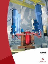
Chooz B1, France (N4, 1,500 MWe) upper internals.<br />
24 I