Areva EPR
Areva EPR
Areva EPR

You also want an ePaper? Increase the reach of your titles
YUMPU automatically turns print PDFs into web optimized ePapers that Google loves.
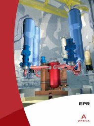
The dedicated corium spreading and cooling area is a core-catcher<br />
equipped with a solid metal structure and covered with “sacrificial”<br />
concrete. It aims to protect the nuclear island basemat from any<br />
damage, its lower section features cooling channels in which water<br />
circulates. The aim of its large spreading surface area (170 m 2 ) is to<br />
promote the cooling of the corium.<br />
The transfer of the corium from the reactor pit to the spreading area<br />
would be initiated by a passive device: a steel “plug” melting under<br />
the effect of the heat from the corium.<br />
After spreading, the flooding of the corium would also be initiated by<br />
a passive fusible plug-based device. It would then be cooled, still<br />
passively, by gravity injection of water from the tank located inside the<br />
containment and by evaporation.<br />
The effectiveness of the cooling would then provide stabilization of the<br />
corium in a few hours and its complete solidification in a few days.<br />
Containment heat removal system<br />
and long-term residual heat removal device<br />
In the eventuality of a severe accident, to prevent the containment<br />
from losing its long-term integrity, means would have to be provided<br />
to control the pressure inside the containment and to stop it from<br />
rising under the effect of residual heat. A dedicated dual-train spray<br />
system with heat-exchangers and dedicated heat sink is provided<br />
to fulfil this function. A long time period would be available for the<br />
deployment of this system by the operators: at least 12 hours owing<br />
to the large volume of the containment (80,000 m 3 ).<br />
A second mode of operation of the containment heat removal system<br />
enables to feed water directly into the core-catcher, instead of into<br />
the spray system.<br />
Collection of inter-containment leaks<br />
In the eventuality of a core melt leading to vessel failure, the<br />
containment remains the last of the three containment barriers; this<br />
means that provisions must be taken to make sure that it remains<br />
undamaged and leak-tight. For the <strong>EPR</strong>, the following measures have<br />
been adopted:<br />
•a 6 mm thick metal liner internally covers the pre-stressed concrete<br />
inner shell,<br />
• the internal containment penetrations are equipped with redundant<br />
isolation valves and leak recovery devices to avoid any containment<br />
bypass,<br />
• the architecture of the peripheral buildings and the sealing systems<br />
of the penetrations rule out any risk of direct leakage from the inner<br />
containment to the environment,<br />
• the space between the inner and outer shells of the containment is<br />
passively kept at slight negative pressure to enable the leaks to<br />
collect there,<br />
• these provisions are supplemented by a containment ventilation<br />
system and a filter system upstream of the stack.<br />
Containment heat removal system<br />
Spray nozzles<br />
x<br />
x<br />
Passive<br />
flooding<br />
device<br />
x<br />
CHRS<br />
(2x)<br />
Corium<br />
spreading area<br />
In-containment refueling<br />
water storage tank<br />
Melt flooding via cooling device<br />
and lateral gap<br />
x<br />
Water level in case of water<br />
injection into spreading area<br />
FL Flow limiter<br />
I 51