Areva EPR
Areva EPR
Areva EPR

You also want an ePaper? Increase the reach of your titles
YUMPU automatically turns print PDFs into web optimized ePapers that Google loves.
SAFETY INJECTION /<br />
RESIDUAL HEAT REMOVAL<br />
The Safety Injection System (SIS/RHRS) comprises the Medium Head<br />
Safety Injection System, the Accumulators, the Low Head Safety<br />
Injection System and the In-Containment Refueling Water Storage<br />
Tank. The system performs a dual function both during the normal<br />
operating conditions in RHR mode and in the event of an accident.<br />
The system consists of four separate and independent trains, each<br />
providing the capability for injection into the RCS by an Accumulator,<br />
a Medium Head Safety Injection (MHSI) pump and a Low Head<br />
Safety Injection (LHSI) pump, with a heat exchanger at the pump<br />
outlet.<br />
During normal operating conditions, the system in RHR mode:<br />
• provides the capability for heat transfer from the RCS to the<br />
Component Cooling Water System (CCWS) when heat transfer<br />
via the Steam Generators (SG) is no longer sufficiently effective<br />
(at an RCS temperature of less than 120 °C in normal operation),<br />
• transfers heat continuously from the RCS or the reactor refueling<br />
pool to the CCWS during cold shutdown and refueling shutdown,<br />
as long as any fuel assemblies remain inside the containment.<br />
In the event of an assumed accident and in conjunction with the<br />
CCWS and the Essential Service Water System (ESWS), the SIS<br />
in RHR mode maintains the RCS core outlet and hot leg<br />
temperatures below 180 °C following a reactor shutdown.<br />
The four redundant and independent SIS/RHRS trains are arranged<br />
in separate divisions in the Safeguard Buildings. Each train is<br />
connected to one dedicated RCS loop and is designed to provide<br />
the necessary injection capability required to mitigate accident<br />
conditions. This configuration greatly simplifies the system design.<br />
The design also makes it possible to have extended periods available<br />
for carrying out preventive maintenance or repairs. For example,<br />
preventive maintenance can be carried out on one complete safety<br />
train during power operation.<br />
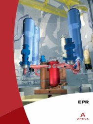
SI/RHR System<br />
– Four train SIS<br />
– In-containment refueling<br />
water storage tank<br />
– Combined RHRS/LHSI<br />
RHR<br />
SI<br />
Hot legs<br />
LHSI RHR<br />
pump<br />
LHSI RHR<br />
pump<br />
LHSI RHR<br />
pump<br />
Accumulators<br />
Accumulators<br />
LHSI RHR<br />
pump<br />
MHSI<br />
pump<br />
MHSI<br />
pump<br />
Cold legs<br />
MHSI<br />
pump<br />
MHSI<br />
pump<br />
IRWST<br />
IRWST<br />
Division 1 Division 2<br />
Division 3 Division 4<br />
I 35