Areva EPR
Areva EPR
Areva EPR

You also want an ePaper? Increase the reach of your titles
YUMPU automatically turns print PDFs into web optimized ePapers that Google loves.
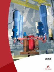
■ <strong>EPR</strong> NUCLEAR ISLAND<br />
<strong>EPR</strong> LAYOUT<br />
7<br />
3<br />
4<br />
1<br />
3<br />
3<br />
2<br />
3<br />
5<br />
4<br />
6<br />
1 Reactor Building<br />
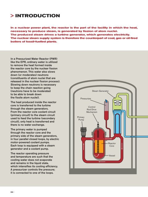
The Reactor Building located in the center of the Nuclear Island houses<br />
the main equipment of the Nuclear Steam Supply System (NSSS)<br />
and the In-Containment Refueling Water Storage Tank (IRWST). Its<br />
main function is to ensure protection of the environment against internal<br />
and external hazards consequences under all circumstances. It<br />
consists of a cylindrical pre-stressed inner containment with a metallic<br />
liner surrounded by an outer reinforced concrete shell.<br />
The main steam and feedwater valves are housed in dedicated<br />
reinforced concrete compartments adjacent to the Reactor Building.<br />
The primary system arrangement is characterized by:<br />
• pressurizer located in a separate area,<br />
• concrete walls between the loops and between the hot and cold<br />
legs of each loop,<br />
• concrete wall (secondary shield wall) around the primary system<br />
to protect the containment from missiles and to reduce the spread<br />
of radiation from the primary system to the surrounding areas.<br />
2 Fuel Building<br />
The Fuel Building, located on the same common basemat as the<br />
Reactor Building and the Safeguard Buildings, houses the fresh fuel,<br />
the spent fuel in an interim fuel storage pool and associated handling<br />
equipment. Operating compartments and passageways, equipment<br />
compartments, valve compartments and the connecting pipe ducts<br />
are separated within the building. Areas of high activity are separated<br />
from areas of low activity by means of shielding facilities. The<br />
mechanical floor houses the fuel pool cooling system, the emergency<br />
boration system, and the chemical and volume control system. The<br />
redundant trains of these systems are physically separated by a wall<br />
into two building parts.<br />
3 The Safeguard Buildings<br />
The four Safeguard Buildings house the safeguard systems such as<br />
the Safety Injection System and the Emergency Feedwater System,<br />
and their support systems. The four different trains of these safeguard<br />
systems are housed in four separate divisions, each located in one<br />
of the four Safeguard Buildings.<br />
The Low Head Safety Injection System is combined with the<br />
Residual Heat Removal System. They are arranged at the inner areas<br />
in the radiologically controlled areas, whereas the corresponding<br />
Component Cooling and Emergency Feedwater Systems are<br />
installed at the outer areas in the classified non-controlled areas.<br />
The Main Control Room is located in one of the Safeguard Buildings.<br />
4 Diesel Buildings<br />
The two Diesel Buildings shelter the four emergency Diesel<br />
generators and their support systems, and supply electricity to the<br />
safeguard trains in the event of a complete loss of electrical power.<br />
The physical separation of these two buildings provides additional<br />
protection.<br />
10 I