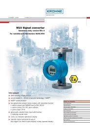
TI20 Intelligent Temperature Transmitter
TI20 Intelligent Temperature Transmitter
TI20 Intelligent Temperature Transmitter
You also want an ePaper? Increase the reach of your titles
YUMPU automatically turns print PDFs into web optimized ePapers that Google loves.
Product Specifications 05.97 PSS EMT0111 A-(en)<br />
<strong>TI20</strong><br />
<strong>Intelligent</strong> <strong>Temperature</strong> <strong>Transmitter</strong><br />
These intelligent transmitters are designed to perform measurements of temperature, voltage or resistance. The<br />
transmitters are approved for use in hazardous areas. They can either be mounted in a standard head housing<br />
as well as at a DIN rail. A rugged field housing allows EEx d applications. Bidirectional communication via the<br />
HART protocol is possible using the PC software ABO991 or the Universal Hand Terminal HT991. For the<br />
FOXCOM version configuration is made with the Hand Held Terminal HHT, PC-Software PC10 or directly from<br />
the I/A Series System.<br />
FEATURES<br />
• For all temperature sensors<br />
(resistance thermometers and thermocouples)<br />
• High accuracy over the complete temperature<br />
range<br />
• Intrinsically safe EEx ia IIC T4 ... T6 or<br />
EEx d in the field housing<br />
• Galvanic isolation between input and output<br />
• Open sensor and short-circuit detection<br />
• Can be mounted in a head housing,<br />
at a DIN rail or in a field housing<br />
• Continuous self diagnostics<br />
• Communication via HART or FOXCOM protocol<br />
(4 ... 20 mA and FOXCOM Digital)<br />
• Fast adaptation to a different measuring range<br />
without recalibration<br />
• Safety value configurable<br />
• Integrated current source for loop-check<br />
• Write protection<br />
• Redocumentation of measuring point<br />
• Customized characterization<br />
• Local display freely configurable<br />
• Conventional operation by means of the local<br />
keys of the LCD configurator<br />
• Software lock for local keys control<br />
• EMC protection in accordance with<br />
international standards and laws (CE)
2 <strong>TI20</strong> PSS EMT0111 A-(en)<br />
TECHNICAL DATA<br />
Specifications according to DIN IEC 770<br />
Reference operating<br />
Power supply .<br />
Ambient temperature.<br />
Vibration . . . .<br />
Humidity...............<br />
Input<br />
Resistance Thermometer<br />
Sensors . . . . .<br />
Sensor connection<br />
Temp. measurement<br />
Difference-temperature<br />
2-Channel<br />
Temp. measurem.<br />
Averaged...........<br />
Accuracy PV 1)<br />
Table 1<br />
Resistance<br />
thermometer<br />
Pt100 DIN IEC<br />
Pt100 SAMA<br />
Ni100 DIN<br />
Cu10 DIN 43760<br />
SAMA Ni.<br />
Ni120 MINCO<br />
Maximum line resistance<br />
with 2-, 3-, 4-wire<br />
measurement...........<br />
Maximum difference<br />
with 3-, 4-wire<br />
measurement...........<br />
Thermocouple<br />
Sensors . . . . .<br />
Measurement mode<br />
Temp. measurement<br />
Diff.-temp. meas.<br />
Accuracy PV 1)<br />
Table 2<br />
Thermocouples<br />
DIN IEC 584 T1,<br />
DIN IEC 584 T1,<br />
DIN IEC 584 T1,<br />
DIN IEC 584 T1,<br />
DIN IEC 584 T1,<br />
DIN 43 710, L<br />
DIN IEC 584 T1,<br />
DIN IEC 584 T1,<br />
DIN IEC 584 T1,<br />
DIN IEC 584 T1,<br />
DIN 43 710, U<br />
conditions<br />
. DC 24 V<br />
. 25 °C<br />
. none<br />
50%<br />
RTD<br />
. see table<br />
. 2-, 3-, 4-wire<br />
. 2-wire<br />
. 2-wire<br />
2-wire<br />
.......... 0.025%<br />
of input reading<br />
or value from<br />
Nominal range<br />
[°C]<br />
-200 ... 850<br />
-200 ... 650<br />
-60 ... 180<br />
-70 ... 150<br />
-130 ... 315<br />
-80 ... 320<br />
R L≤50 Ω<br />
R Ldiff ≤5Ω<br />
. see table<br />
. 2-wire<br />
. 2-wire, with<br />
junction temperature<br />
......... 0.025%<br />
of input reading<br />
or value from<br />
Nominal range<br />
[°C]<br />
43 ... 1820<br />
0 ... 2320<br />
-270 ... 1000<br />
-210 ... 1200<br />
-270 ... 1372<br />
-200 ... 900<br />
-270 ... 1300<br />
-50 ... 1768<br />
-50 ... 1768<br />
-270 ... 400<br />
-200 ... 600<br />
(PV)<br />
table 1 2)<br />
Accuracy<br />
PV<br />
0.07 K<br />
0.07 K<br />
0.05 K<br />
1.00 K<br />
0.07 K<br />
0.15 K<br />
wire<br />
given lowest<br />
(PV)<br />
table 2 2)<br />
Accuracy<br />
PV<br />
0.60 K 3)<br />
0.40 K<br />
0.15 K 4)<br />
0.15 K<br />
0.15 K 4)<br />
0.20 K<br />
0.40 K 5)<br />
0.40 K<br />
0.40 K<br />
0.30 K 6)<br />
0.30 K 5) Additional error due to cold junction compensation:<br />
Internal cold junction compensation<br />
TypeS,R...............≤1.00 K<br />
Type B . . . . . . . . . . . . . . . . . . ≤ 1.00 K 3)<br />
Type U,T,N,L,K,J,E,C . . . . . ≤ 0.50 K<br />
With Ni100 element 7)<br />
TypeS,R ..............≤1.00 K<br />
Type B . . . . . . . . . . . . . . . . . . ≤ 1.00 K 3)<br />
Type U,T,N,L,K,J,E,C . . . . . ≤ 0.50 K<br />
Maximum line resistane . . . R L ≤ 3kΩ<br />
Voltage<br />
Measurement mode<br />
mV....................2-wire<br />
Accuracy PV 1) ..........0.025%<br />
of input reading (PV)<br />
or value from table 3 2)<br />
Table 3<br />
Nominal range Accuracy<br />
Voltage<br />
max.<br />
PV<br />
-15 ... 115 mV 6 µV<br />
Resistance<br />
Measurement mode<br />
Resistance . . . . . . . . . . . . 2-, 3-, 4-wire<br />
Diff.-resistance.........2-wire<br />
2-channel<br />
Absolute meas. . . . . . . . 2-wire<br />
Averaged meas. . . . . . . 2-wire<br />
Accuracy PV 1) ..........0.025%<br />
of input reading (PV)<br />
or value from table 4 2)<br />
Table 4<br />
Nominal range Accuracy<br />
7) 8)<br />
Resistance max. PV<br />
-500 ... 500 Ω 20 mΩ<br />
Characteristic<br />
Characteristic . . . . . . . . . . . linear or<br />
customized with max.<br />
22 pairs of values<br />
1) Digital value PV (PV = primary variable)<br />
for HART and FOXCOM<br />
2) Whichever is greater<br />
3) At range > 100 °C<br />
4) At range > -200 °C<br />
5) At range > -100 °C<br />
6) At range > -150 °C<br />
8) Inclusively the resistance of the current-carrying wires<br />
. . . . . . . . .<br />
. . .<br />
. . . . . . . . .<br />
. . . . . . . . . 1<br />
. .<br />
. . .<br />
751<br />
per<br />
. . . . . . . . . 2<br />
. .<br />
. . . . .<br />
B<br />
C<br />
E<br />
J<br />
K<br />
N<br />
R<br />
S<br />
T<br />
9) Negativ numbers when diff.-measurement
PSS EMT0111 A-(en) <strong>TI20</strong> 3<br />
Output<br />
Analog<br />
Characteristic. . . . . . . . . . . linear<br />
Signal range. . . . . . . . . . . . 4 ... 20 mA / 20 ... 4 mA<br />
Outputrange........... 3.8...20.5mA<br />
Permittedload.......... RBmax<br />
=<br />
Us<br />
− 12 V<br />
0.02 A<br />
Accuracy AO . . . . . . . . . . . Accuracy PV plus 0.05 %<br />
Resolution............. 3.5µA<br />
Digital<br />
For connection to FBM 18, 39, 43 or 44 of<br />
I/A Series System<br />
LCD Configurator 1)<br />
One line<br />
LCD configurator. . . . . . .<br />
Three line<br />
LCD configurator. . . . . . .<br />
4-digits, without unit<br />
5-digits, sign plus unit<br />
(7-digits alphanumeric),<br />
bar graph display<br />
0 ... 100 %<br />
Failure handling<br />
Substitute value . . . . . . . . . store last good value /<br />
safety value<br />
Failsafevalue........... 3.6...23mA<br />
Sensor fault detection<br />
Open wire<br />
TC/RTD,R............<br />
ShortcircuitRTD/R.....<br />
Supply voltage 2)<br />
DC 12 ... 42 V<br />
Supply ripple V ss ........<br />
≥3kΩ/≥500 Ω<br />
≤6Ω/≤1Ω<br />
≤1%p.p.<br />
Environmental conditions 2)<br />
<strong>Temperature</strong> range . . . . . . -40 ... +85 °C<br />
With LCD configurator . . . . -30 ... +70 °C<br />
Relative humidity . . . . . . . . ≤ 100 %<br />
Condensation. . . . . . . . . . . permitted<br />
Transportation /<br />
Storage temperature . . . . . -50 ... +85 °C<br />
The device can be operated at a class D2 location in<br />
accordance to DIN IEC 654, part 1.<br />
Protection class<br />
With field housing<br />
Code–F............... IP66,NEMA4X<br />
Transitional behavior<br />
Noise suppression<br />
Commonmode........ ≤250 V rms<br />
Common mode rej. . . . . 120 dB 3)<br />
Series mode rej. . . . . . . 48 dB 4)<br />
Mains<br />
synchronization. . . . . . . . 50 Hz / 60 Hz<br />
Dynamic behavior<br />
Damping (63% time). . . . 0 ... 32 s configurable<br />
Step response . . . . . . . . 1 s, typ.<br />
Startup.............. 7s<br />
Update rate<br />
analog............... 150ms<br />
digital ............... 100ms(FOXCOM)<br />
Long term stabiliy<br />
analog............... ≤0.05 %/Year + 20 µA<br />
digital ............... ≤0.05 %/Year<br />
Effects of influencing quantities<br />
on the accurcay<br />
Ambient temperature<br />
analog . . . . . . . . . . . . . . . Accuracy AO x 0.15/10 K<br />
digital ............... 0.1xPV/10K<br />
Supply voltage<br />
analog............... 0.005%/V<br />
digital . . . . . . . . . . . . . . . no influence<br />
Load<br />
analog............... 0.05% 5)<br />
digital . . . . . . . . . . . . . . . no influence<br />
Humidity . . . . . . . . . . . . . . no influence<br />
Electromagnetic compatibility EMC<br />
Operating conditions . . . . . industrial environment<br />
Immunity according to<br />
- EN 50082-2 . . . . . . . . . . . fulfilled 6)<br />
Emission according to<br />
- EN 55011,<br />
Group 1, Class A . . . . . . fulfilled<br />
- EN 50081-2 . . . . . . . . . . fulfilled<br />
Electrical connection<br />
Output<br />
Screw terminals. . . . . . . . .<br />
Sensor<br />
Solder posts or<br />
Screw terminals. . . . . . . . .<br />
wire cross section<br />
max. 1.5 mm 2<br />
wire cross section<br />
max. 1.5 mm 2<br />
Mechanical stress<br />
Shock ................<br />
Vibration...............<br />
Vibration...............<br />
perDINIEC7706.2.13<br />
0.25mm/10...60Hz<br />
3g/60...500Hz<br />
1) Accessory only in combination with sensor connections<br />
Code 1, standard screws<br />
2) With explosionproof devices, please observe certificates<br />
of conformity for data<br />
3) Short circuited input<br />
4) Smaller than 4.5 mVrms<br />
5) When load is changed within the full range<br />
6) Acceptance criterion A: ± 1%F.S.<br />
Passing deviations > ± 1 % are possible
4 <strong>TI20</strong> PSS EMT0111 A-(en)<br />
Communication 1)<br />
HART<br />
Communication standard . HART protokol<br />
Load.................. ≥250 Ω<br />
PC software . . . . . . . . . . . . ABO991(Rev. greater 3.0)<br />
Modem ............... MOD991forPC<br />
Universal Hand Terminal. . HT991<br />
FOXCOM<br />
Foxboro protokol . . . . . . . .<br />
Load..................<br />
PC software . . . . . . . . . . . .<br />
Handterminal...........<br />
Weight<br />
<strong>Transmitter</strong><br />
Sensor connections<br />
Code 1 . . . . . . . . . . . . . . . .<br />
Sensor connections<br />
Codes 2 and 3 . . . . . . . . . .<br />
<strong>Transmitter</strong> with<br />
field housing,<br />
Code –F. . . . . . . . . . . . . . .<br />
LCD configurator<br />
One line . . . . . . . . . . . . .<br />
Three line . . . . . . . . . . . .<br />
analog or digital<br />
≥200 Ω<br />
PC10 (incl. Modem)<br />
HHT<br />
approx. 140 g<br />
approx. 110 g<br />
approx. 1 470 g<br />
approx. 20 g<br />
approx. 60 g<br />
SAFETY REQUIREMENTS<br />
CE marking<br />
Electromagnetic<br />
compatibility............ 89/336/EWG<br />
Low-voltage regulation . . . 73/23/EWG not applicable<br />
Safety<br />
As per EN 61010-1<br />
(rsp. IEC 1010-1). . . . . . . .<br />
Internal fuses . . . . . . . . . . .<br />
External fuses . . . . . . . . . .<br />
Explosion protection<br />
Safety class III<br />
none<br />
Limitation of power supplies<br />
for fire protection have to be<br />
observed due to<br />
EN 61010-1, appendix F<br />
(resp. IEC 1010-1)<br />
2) 3)<br />
See certificates of conformity,<br />
Document No. EX EMT0111 A-(de)(en)<br />
Type of protection . . . . . . . EEx ia IIC T4 ... T6<br />
Type BIA 409<br />
Certificate of conformity. . . KEMA No. Ex-95.D.4252 X<br />
Certified as per CENELEC standard for the type of<br />
protection intrinsic safety EEx ia IIC, temperature class<br />
T4 ... T6 for hazardous areas.<br />
1) Optional<br />
2) Only when ordered<br />
3) National requirements have to be observed<br />
4) Partly with appropriate housing<br />
<strong>Temperature</strong> transmitter for use in hazardous areas in<br />
circuits certified as being intrinsically safe and having the<br />
following maximum values:<br />
U 0 I 0 P i Temp.<br />
class<br />
Max. values<br />
0.9 W T4<br />
30 V 125 mA 0.5 W<br />
0.7 W<br />
T5<br />
0.5 W T6<br />
Internal capacitance . . . . . . 1 nF<br />
Internal inductance . . . . . . . negligible<br />
Sensor side<br />
Typeofprotection............... EExiaIIC<br />
with the following maximum values:<br />
max. values<br />
U 0 I 0<br />
14.6 V 9.2 mA<br />
Ambient<br />
temp.<br />
80 °C<br />
40 °C<br />
For the limits of L a and C a please refer to the Certificate<br />
of conformity EX EMT0111 A-(de)(en).<br />
Explosion protection zone 2<br />
Type of protection . . . . . . . . Ex N IIC T4 ... T6<br />
Non-incendive, BS 6941<br />
Type BN 409<br />
Test certificate . . . . . . . . . . . KEMA No. Ex-95.Y.4253 X<br />
Max. values<br />
Voltage...............30V<br />
Current...............125mA<br />
Power................900mW<br />
Ambient temperature . . . . 70 °C for T4 and T5<br />
40 °C for T6<br />
For connection to a thermocouple or an RTD sensor.<br />
Explosionproof CENELEC<br />
With field housing Code –F<br />
Type of protection . . . . . . . . EEx d II C T6<br />
Typ BDE 409<br />
Certificate of conformity . . . KEMA No Ex-95.D-4462<br />
Certified as per CENELEC standard for hazardous areas.<br />
Electrical data<br />
Voltage...............≤DC 42 V<br />
Current...............≤35 mA<br />
Power................≤1W<br />
Ambient temperature . . . . -40 °C ... +70 °C<br />
The electrical connection in type of protection EEx d has<br />
to be executed with approved cables and cable glands<br />
or pipes (not part of delivery).<br />
Cable entry 1/2 - 14 NPT only.<br />
Further certifications in preparation: 4)<br />
Intrinsically safe (FM/CSA/SAA)<br />
Explosionproof (FM/CSA)<br />
Non-incendive (FM/CSA)<br />
Non-sparking (SAA)<br />
Flameproof (SAA)
PSS EMT0111 A-(en) <strong>TI20</strong> 5<br />
ELECTRICAL CONNECTION<br />
Sensor- and loopwires:<br />
For the selection of the sensor- and the loopwires, please observe the national safety requirements.<br />
Resistance Thermometer or Resistor<br />
2-wire 3-wire 4-wire<br />
∆ 2-wire ( ϑ1 - ϑ2 )<br />
2-wire average (<br />
ϑ1 + ϑ2<br />
)<br />
2<br />
2 x 2-wire<br />
ϑ<br />
1)<br />
ϑ1<br />
ϑ ϑ ϑ2<br />
1 2 3 4<br />
Thermocouple or Voltage<br />
Thermocouple<br />
or Voltage<br />
Difference<br />
( ϑ1 ϑ2 )<br />
Thermocouple with external<br />
cold junction compensation<br />
1)<br />
ϑ2<br />
ϑ1<br />
2)<br />
1 2 3 4<br />
Supply, Loop signal and Communication (HART or FOXCOM)<br />
HT991 (HART)<br />
or<br />
HHT (FoxCom)<br />
≥ 250 Ω for HART<br />
≥ 200 Ω for FoxCom<br />
1) Short-circuit at transmitter 2) Option for mounting in a head housing
6 <strong>TI20</strong> PSS EMT0111 A-(en)<br />
MOUNTING<br />
NOTE<br />
When installing the transmitter or mounting in a housing,<br />
please observe the national safety requirements.<br />
DIN rail mounting<br />
The electronic can be mounted at a DIN rail:<br />
hat rail 35 mm according to EN 50 022 or<br />
monting rail form G according to EN 50 035.<br />
Head Housing<br />
The electronic with sensor connections code 2 and 3 are<br />
intended to be mounted into a head housing as per DIN<br />
43729 Type TZ-A/BL. Gauge slides as per DIN 43735<br />
respectively DIN 43762.<br />
Terminalsockettype............. B<br />
Max. numbers of terminals . . . . . . . . 4<br />
Distance between<br />
terminals(overallsize) ........... max.33mm<br />
SENSOR CONNECTIONS CODE 1<br />
STANDARD SCREWS<br />
Pg 16<br />
M24x1.5<br />
DIN RAIL<br />
BRACKET FOR DIN RAIL MOUNTING<br />
Field Housing<br />
The electronic can be mounted in a field housing. Therefore<br />
a mountig kit is available (wall or pipe mounting).<br />
For delivery with LCD configurator the cover has a glass<br />
window.<br />
Terminal socket<br />
33<br />
1.30<br />
mm<br />
in<br />
10<br />
0.39<br />
~24<br />
0.94
PSS EMT0111 A-(en) <strong>TI20</strong> 7<br />
Mounting instructions for type BIA 409<br />
The <strong>Transmitter</strong> must be mounted in an enclosure<br />
providing a degree of protection of at least IP 20 per IEC<br />
529, when installed in an indoor location, and in an<br />
enclosure providing a degree of protection of at least IP<br />
44 per IEC 529, when installed in an outdoor location.<br />
Mounting instructions for type BN 409<br />
A <strong>Temperature</strong> <strong>Transmitter</strong> without enclosure must be<br />
mounted in an enclosure providing a degree of<br />
protection of at least IP 54 per IEC 529.<br />
The degree of protection of at least IP 54 to IEC 529 is<br />
only achieved if cable entries are used that are suitable<br />
for the application and correctly installed.<br />
Cable entries must comply with Clause 5.3.2 of<br />
BS 6941.<br />
OVERVIEW ACCESSORIES<br />
Ni100 Element for cold junction temperature<br />
compensation<br />
Brackets for DIN rail mounting<br />
Mounting in a head housing<br />
DIN RAIL<br />
BRACKET FOR DIN RAIL MOUNTING<br />
(2 BRACKETS PER TRANSMITTER)<br />
One line LCD configurator<br />
Three line LCD configurator<br />
1 0 0.0<br />
- 2 0 0.0 0 C<br />
C E L S I U S
8 <strong>TI20</strong> PSS EMT0111 A-(en)<br />
MODEL CODES<br />
<strong>TI20</strong> <strong>Intelligent</strong> <strong>Temperature</strong> <strong>Transmitter</strong><br />
Package Configuration<br />
–B Basic Unit, no housing and no sensor<br />
–F Field housing without sensor<br />
–K Built in head housing with sensor<br />
(<strong>Temperature</strong> sensors with head housings see PSS EMT1000)<br />
Output<br />
I 4-20 mA (Definition of option –T is required to configure transmitter)<br />
T 4-20 mA with HART communication (Accessories for HART devices PSS EMO0100)<br />
D 4-20 mA with FOXCOM communication<br />
Sensor Connections<br />
1 Standard screws<br />
2 Solder terminals (c)<br />
3 Compact screws (c)<br />
Electrical Classification<br />
EAA CENELEC EEx ia IIC T6<br />
EDZ CENELEC EEx d (for package configuration –F only)<br />
KNZ BS 6941 non-incendive, Ex N IIC T6, Zone 2<br />
FAA FM intrinsically safe (pending)<br />
FDZ FM explosionproof (for package configuration –F only)<br />
SAA SAA intrinsically safe (pending)<br />
CAA CSA intrinsically safe (pending)<br />
ZZZ For general purpose areas; not intrinsically safe nor explosionproof<br />
Optional Features<br />
–T Custom Configuration<br />
–S Kit for DIN rail mounting (for sensor connections code 1 or 3 only)<br />
–A One line LCD configurator (a)<br />
–B Three line LCD configurator (a)<br />
–F Remote cold junction sensor Ni100 for thermocouple measurement<br />
–L TAG-Number labeling on sticker<br />
Example Model Code:<br />
<strong>TI20</strong> –B T 1 EAA –S–B<br />
(a) for sensor connections code 1 only<br />
(c) not for package configuration –F<br />
Product Specifications for <strong>Intelligent</strong> <strong>Transmitter</strong>s:<br />
PSS EMP0510 A-(en)<br />
PSS EMP0610 A-(en)<br />
PSS EMP0520 A-(en)<br />
PSS EMP0620 A-(en)<br />
PSS EMP0530 A-(en)<br />
PSS EMP0630 A-(en)<br />
131GP<br />
141GP}<br />
132AP<br />
142AP}<br />
133DP<br />
143AP}<br />
<strong>Intelligent</strong> Gauge Pressure <strong>Transmitter</strong><br />
<strong>Intelligent</strong> Absolute Pressure <strong>Transmitter</strong><br />
<strong>Intelligent</strong> d/p <strong>Transmitter</strong><br />
PSS EML2510 A-(en) 134FP <strong>Intelligent</strong> d/p <strong>Transmitter</strong> - Flange mounted<br />
PSS EML1510 A-(en) 134LVD <strong>Intelligent</strong> Buoyancy <strong>Transmitter</strong><br />
PSS EML0510 A-(en) 134LD <strong>Intelligent</strong> Buoyancy <strong>Transmitter</strong> with Torque Tube<br />
PSS EML9510 A-(en) 104 ... Accessories for Buoyancy <strong>Transmitter</strong>s<br />
PSS EMO0100 A-(en)<br />
Accessories for Devices with HART Protocol<br />
PSS 2A-1Z3 A HHT I/A Series Hand-Held Terminal<br />
PSS 2A-1Z3 C PC10 <strong>Intelligent</strong> <strong>Transmitter</strong> Configurator
PSS EMT0111 A-(en) <strong>TI20</strong> 9<br />
DIMENSIONS<br />
<strong>Temperature</strong> <strong>Transmitter</strong><br />
mm<br />
in<br />
42,8<br />
1.685<br />
1<br />
2 3<br />
4<br />
SENSOR CONNECTIONS<br />
CODE 1<br />
STANDARD SCREWS<br />
32,64<br />
1.285<br />
44,2<br />
1.740<br />
28,45<br />
1.120<br />
1 2 3 4<br />
26,16<br />
1.030<br />
SENSOR CONNECTIONS<br />
CODE 2<br />
SOLDER TERMINALS<br />
33<br />
1.3<br />
44,2<br />
1.740<br />
1 2 3 4<br />
SENSOR CONNECTIONS<br />
CODE 3<br />
COMPACT SCREWS<br />
59,69<br />
2.350<br />
29,5<br />
1.160<br />
One line LCD configurator<br />
50,00<br />
1.969<br />
mm<br />
in<br />
Three line LCD configurator<br />
63,5<br />
2.50<br />
42,8<br />
1.685<br />
32,64<br />
1.285<br />
53,82<br />
2.119<br />
42,8<br />
1.685<br />
32,64<br />
1.285<br />
63,02<br />
2.48<br />
1 0 0.0<br />
- 2 0 0.0 0 C<br />
C E L S I U S
72<br />
2.83<br />
106<br />
4.17<br />
36<br />
1.42<br />
25<br />
0.98<br />
10 <strong>TI20</strong> PSS EMT0111 A-(en)<br />
DIMENSIONS (continued)<br />
DIN rail mounting<br />
mm<br />
in<br />
11<br />
0.44<br />
DIN RAIL<br />
FIXING SCREW<br />
BRACKET FOR DIN RAIL MOUNTING<br />
Field housing<br />
DN50 OR 2 in<br />
X<br />
mm<br />
in<br />
PIPE (BY USER)<br />
29,4<br />
1.16<br />
PIPE MOUNTING<br />
109<br />
4.3<br />
119<br />
4.7<br />
9<br />
0.35<br />
1/2 NPT, 2 PLACES<br />
WALL MOUNTING<br />
10<br />
0.39<br />
45<br />
1.77<br />
NOTE 2<br />
72<br />
2.83<br />
89<br />
3.5<br />
DIMENSION X (NOTE 1)<br />
NOTES<br />
1.<br />
ALLOW 51 mm (2 in) CLEARANCE<br />
FOR COVER REMOVAL<br />
WITHOUT LCD COFIGURATOR<br />
WITH LCD COFIGURATOR<br />
87<br />
3.4<br />
112<br />
4.4<br />
2. EXTERNAL COVER LOCK AND<br />
GROUND SCREW LOCATION FOR<br />
ELECTRICAL CLASSIFICATION<br />
CODE EDZ AND FDZ
Form Sheet for Configuration 01.96 FS EMT0111 B-(en)<br />
<strong>TI20</strong><br />
<strong>Intelligent</strong> <strong>Temperature</strong> <strong>Transmitter</strong><br />
Standard Configuration<br />
Sensor .................... PT100<br />
Unit.. ..................... °C<br />
Measurementmode .......... 4-wire<br />
Measurementrange .......... 0...150°C<br />
Damping ................... 1sec<br />
Characteristic................ linear<br />
Failure handling<br />
Safetyvalue ................. 3.6mA<br />
Resetsubstitutevalue ......... auto<br />
Localkeys...................... active<br />
Noise Suppression<br />
MainsFrequency ............. 50Hz,highfilter<br />
HARTaddress................... 0<br />
Configuration according to customer:<br />
When ordering a configuration differing from the standard configuration, please fill in form below:<br />
Measurement point<br />
TAG Number:<br />
Description :<br />
Date :<br />
Sensor<br />
❑ Resistance Thermometer RTD<br />
Unit.................... °C .............. ❍<br />
°F............... ❑<br />
°R .............. ❑<br />
K ............... ❑<br />
Ω............... ❑<br />
SensorType............. Pt100DIN........ ❍<br />
Pt100SAMA...... ❑<br />
Ni100DIN........ ❑<br />
Cu10DIN........ ❑<br />
SAMANi......... ❑<br />
Ni120MINCO..... ❑<br />
1) ...........<br />
Special ❑<br />
Measurement Mode<br />
Temp.-measurement..... 2-wire............ ❑<br />
3-wire............ ❑<br />
4-wire............ ❍<br />
Diff.-temp.-measurement ................... ❑<br />
2-channnelabsolutemeasurement .......... ❑<br />
2-channelaveragedmeasurement........... ❑<br />
Opensensordetection..... On.............. ❍<br />
Off.............. ❑<br />
❑Thermocouple<br />
Unit.................... °C .............. ❑<br />
°F............... ❑<br />
°R .............. ❑<br />
K ............... ❑<br />
mV.............. ❑<br />
Sensortype.............. B ............... ❑<br />
C............... ❑<br />
E ............... ❑<br />
J................ ❑<br />
K ............... ❑<br />
L ............... ❑<br />
N............... ❑<br />
R............... ❑<br />
S ............... ❑<br />
T ............... ❑<br />
U............... ❑<br />
Special 1) ......... ❑<br />
Measurement Mode<br />
<strong>Temperature</strong>measurement ................. ❑<br />
Coldjunctioncomp..... intern............ ❑<br />
Ni 100 2) ......... ❑<br />
none ............ ❑<br />
fixtemperature .... ❑<br />
Fix cold junction temp.<br />
Differencetemperature..................... ❑<br />
Lowest junction temp. 3)<br />
Opensensordetection..... On.............. ❍<br />
Off.............. ❑<br />
❍ = Standard Configuration<br />
1) On request. Curve has to be supplied<br />
2) Accessories<br />
3) Lowest temperature at cold junction<br />
4) Via customized characteristic<br />
5) In combination with thermocouples (except type B) or resistance thermometer<br />
6) Update time 300 ms<br />
7) Text can be displayen the “Three line LCD configurator” only<br />
❑Resistance<br />
Unit..................... Ohm.............❑<br />
Special 4) .........❑<br />
Measurement mode<br />
Resistancemeasurement.. 2-wire............❑<br />
3-wire............❑<br />
4-wire............❑<br />
Differentialresistance.......................❑<br />
2-channelabsolutemeasurement..........❑<br />
2-channnelaveragedmeasurement ........❑<br />
❑Voltage<br />
Unit..................... mV ..............❑<br />
Special 4) .........❑<br />
Linearization<br />
Linearwithunit..............................❍<br />
Linear with dew point temp 5) .................❑<br />
Customized ................................❑<br />
Output<br />
❑ Measuring range<br />
Lowerrange.............. 0°C..............❍<br />
........................................❑<br />
Upperrange.............. 150°C ...........❍<br />
........................................❑<br />
Damping(max.60sec)..... 1sec.............❍<br />
........................................❑<br />
Failure handling<br />
❑ Analog output AO<br />
Substitutevalue........... holdlastgoodvalue.❑<br />
Safetyvalue.............. 3.6mA ...........❍<br />
........................................❑<br />
Resetsubstitutevalue...... auto..............❍<br />
manual...........❑<br />
Others<br />
❑ Mains frequency<br />
50Hz,highspeed ...........................❑<br />
50 Hz, high filter 6) ...........................❍<br />
60Hz,highspeed ...........................❑<br />
60 Hz, high filter 6) ...........................❑<br />
❑ LCD Configurator<br />
DisplayPVinunit............................❑<br />
DisplayAOin%.............................❑<br />
DisplayAOinmA............................❑<br />
AlternatingdisplayPV/AOin%................❑<br />
AlternatingdisplayPV/AOinmA...............❑<br />
NoLCDConfigurator.........................❍<br />
Text (max. 7 characters) 7) ....................❑<br />
Language................ German ..........❑<br />
English...........❑<br />
French ...........❑<br />
Spanish ..........❑<br />
Local keys<br />
Keysactive.................................❍<br />
Keysinactive ...............................❑<br />
Message(max.32Characters)....................❑<br />
.................❑
12 <strong>TI20</strong> PSS EMT0111 A-(en)<br />
Subject to alterations - reprinting, copying and translation prohibited. Products and publications are<br />
normally quoted here without reference to existing patents, registered utility models or trademarks.<br />
The lack of any such reference does not justify the assumption that a product or symbol is free.<br />
FOXBORO ECKARDT GmbH<br />
Postfach 50 03 47<br />
D-70333 Stuttgart<br />
Tel. # 49(0)711 502-0<br />
Fax # 49(0)711 502-597 DOKT 533 956 049







![[PSS 1-8A3 A] Model 84F Flanged Body Flowmeters; Model 84W ...](https://img.yumpu.com/33332673/1/190x245/pss-1-8a3-a-model-84f-flanged-body-flowmeters-model-84w-.jpg?quality=85)
