![[PSS 1-8A3 A] Model 84F Flanged Body Flowmeters; Model 84W ...](https://img.yumpu.com/33332673/1/500x640/pss-1-8a3-a-model-84f-flanged-body-flowmeters-model-84w-.jpg)
[PSS 1-8A3 A] Model 84F Flanged Body Flowmeters; Model 84W ...
[PSS 1-8A3 A] Model 84F Flanged Body Flowmeters; Model 84W ...
[PSS 1-8A3 A] Model 84F Flanged Body Flowmeters; Model 84W ...

Create successful ePaper yourself
Turn your PDF publications into a flip-book with our unique Google optimized e-Paper software.
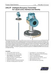
Product Specifications<br />
I/A Series ® Intelligent Vortex <strong>Flowmeters</strong><br />
Foxboro <strong>Model</strong> <strong>84F</strong> <strong>Flanged</strong> <strong>Body</strong> <strong>Flowmeters</strong> and<br />
Foxboro <strong>Model</strong> <strong>84W</strong> Wafer <strong>Body</strong> <strong>Flowmeters</strong><br />
with HART ® Communication Protocol<br />
<strong>PSS</strong> 1-<strong>8A3</strong> A<br />
NEED NEW PHOTO<br />
The Foxboro <strong>Model</strong>s <strong>84F</strong> and <strong>84W</strong> are part of a family of intelligent, high performance, flanged and wafer body<br />
vortex flowmeters. They transmit a 4 to 20 mA or digital multidrop, and a pulse output signal, as applicable,<br />
using HART communication protocol for remote configuration, calibration, and monitoring. An On-board LCD<br />
indicator with pushbuttons is also offered for local configuration.<br />
FEATURES<br />
• Liquid, gas, or steam applications.<br />
• <strong>Flanged</strong> or wafer body designs:<br />
– 3/4 to 12 in (DN 15 to DN 300) flanged body.<br />
– 3/4 to 8 in (DN 15 to DN 200) wafer body.<br />
• Best in class accuracy:<br />
– ±0.5% of reading in liquids.<br />
– ±1.0% of reading in gas and steam.<br />
• Widest rangeability in class.<br />
• Active Tuning:<br />
– Real time Reynolds number (R D ) low flow<br />
correction down to R D of 5000.<br />
– Compensation for piping effects.<br />
– Adaptive filtering and signal conditioning.<br />
– Tunable for specific operating conditions.<br />
• HART communication protocol.<br />
• DirectSense technology with lifetime sensor<br />
warranty.<br />
• New Pulse Output provides raw or scaled<br />
frequency, or total.<br />
• Foxboro has a free-to-use, flow sizing program<br />
on the internet at www.FlowExpertPro.com. See<br />
next page.
<strong>PSS</strong> 1-<strong>8A3</strong> A<br />
Page 2<br />
FlowExpertPro<br />
FlowExpertPro is a program primarily used to size<br />
Foxboro flowmeters. It also ensures that the user has<br />
selected the proper flowmeter type for his application.<br />
Invensys provides this meter selection tool as a free<br />
web site to all users, without the need for registration.<br />
In addition to flowmeter selection and sizing,<br />
FlowExpertPro includes the following features:<br />
• Incorporates a large library of the physical<br />
properties of typical process fluids.<br />
• Displays results in tabular or graphic format.<br />
• Allows user to save, print, or E-mail results.<br />
• Provides reference to applicable flowmeter <strong>PSS</strong>s<br />
and other related flowmeter documentation.<br />
The program calculates minimum and maximum flow<br />
rates, rangeability, pressure loss, and Reynolds<br />
Number, using established flow equations. It also<br />
allows for material and flange selection. You are<br />
invited to visit www.FlowExpertPro.com to access this<br />
program, or contact Invensys for further information,<br />
and technical support.<br />
WIDE VARIETY OF APPLICATIONS<br />
The Foxboro <strong>Model</strong>s <strong>84F</strong> and <strong>84W</strong> set the example<br />
for industry standards whether the application<br />
requires accuracy for totalizing and batching; utility<br />
metering of fluids in the process industries; fuel, air,<br />
steam, or gas metering for the measurement of<br />
energy in any high use application; or stability and<br />
repeatability for process control.<br />
SIMPLE DESIGN FOR BEST PERFORMANCE AND<br />
RELIABILITY<br />
This patented family of vortex flowmeters has the high<br />
accuracy and rangeability of positive displacement<br />
and turbine flowmeters without the mechanical<br />
complexity and high cost. They provide flow rate<br />
accuracy of ±0.5% in liquids and ±1.0% in gas and<br />
steam. It utilizes patented DirectSense technology to<br />
eliminate routine problems encountered with other<br />
vortex meters. DirectSense technology measures<br />
pressure pulses from vortex shedding directly, without<br />
losses due to mechanical linkages. The benefits of<br />
DirectSense technology include:<br />
• Provides best performance in class.<br />
• Increased measurement sensitivity for wider<br />
rangeability.<br />
• Greater immunity to pipe vibration.<br />
• High reliability backed by lifetime sensor<br />
warranty.<br />
• Replaceable sensor without recalibrating.<br />
Because these vortex flowmeters have no moving<br />
parts, they are very durable and reliable. The<br />
simplicity of design ensures low initial cost, low<br />
operating and maintenance costs, which contribute to<br />
an overall lower cost of ownership.<br />
ActiveTuning (See Paragraphs below)<br />
Reynolds Number<br />
Patented algorithm improves accuracy performance<br />
down to an R D of 5000.<br />
Compensations for Piping Effects<br />
When it is not possible to provide the recommended<br />
pipe diameters of unobstructed straight pipe<br />
upstream of the flowmeter, the 84 Series can be<br />
configured to compensate for most of the common<br />
non-ideal upstream conditions, such as elbows and<br />
reducers. Straight runs as short as 5-pipe diameters<br />
can be configured to achieve full accuracy.<br />
Adaptive Filtering and Signal Conditioning<br />
A patented, adaptive filtering algorithm provides realtime,<br />
dynamic frequency filters that follow the vortex<br />
shedding frequency. This results in unsurpassed lowflow<br />
measurement capability and vibration immunity.<br />
This is incorporated with a digital smoothing algorithm<br />
that conditions the raw vortex signal to virtually<br />
eliminate dropped or added pulses, further enhancing<br />
low-flow performance.<br />
Tunable for Specific Operating Conditions<br />
Configurable parameters for Low Flow Cut-in and<br />
damping allow tuning for specific flow conditions.<br />
SIMPLIFIED START-UP<br />
No primary device calculations or mechanical<br />
calibrations are required. The flowmeter is easily<br />
installed and configured. Simply wire it to a proper<br />
power source, an I/O module, or controller, and it is<br />
ready to measure flow.<br />
Invensys will preconfigure the flowmeter using flow<br />
data supplied by the customer. Generically<br />
preconfigured flowmeters can be used as shipped,<br />
but for more precise application, the flowmeter should<br />
be configured to specific process usage. The<br />
configurator allows selection of the fluid type, and<br />
provides general default configurations when process<br />
conditions are not available.<br />
REMOTE MOUNTED ELECTRONICS HOUSING<br />
Remote mounting is offered to allow access to the<br />
amplifier and other housing electronics when the<br />
measurement is not in an easily accessible location.<br />
The remote housing is supported by a bracket, which<br />
in turn mounts to a surface or nominal 2-in or DN 50<br />
pipe. This housing can be located up to a cable<br />
length of 50 ft (15.2 m) from the flowtube without loss<br />
of low level signal.<br />
ISOLATION VALVE<br />
An isolation valve allows the sensor to be removed or<br />
replaced without interrupting the flow in the pipe.
<strong>PSS</strong> 1-<strong>8A3</strong> A<br />
Page 3<br />
MEASUREMENT INTEGRATION<br />
These flowmeters provide efficient integration of<br />
measurements into HART process control schemes,<br />
as follows.<br />
HART -T and -U Versions<br />
These versions operate by using a bidirectional digital<br />
signal superimposed on the 4 to 20 mA current<br />
signal. They are also offered with or without a pulse<br />
output. Remote communication of digital values plus<br />
status and configuration information can be achieved<br />
via HART communication protocol.<br />
Configurators used with the HART versions are:<br />
• The HART Communicator (users having a HART<br />
Communicator for other devices can have them<br />
upgraded with Invensys Foxboro software to<br />
accommodate these flowmeters).<br />
• The Local Digital Indicator/Configurator with<br />
pushbuttons.<br />
With HART, digital multidropping is permitted. This is<br />
the connection of several transmitters to a single<br />
communications line. Up to fifteen transmitters can be<br />
connected on a single twisted pair of wires or over<br />
leased telephone lines.<br />
COMPACT, EFFICIENT, AND DURABLE DESIGN<br />
The flowmeter mounts between ANSI or EN 1092-1<br />
raised face flanges. See <strong>Model</strong> Code section for end<br />
connections offered with each line size. Other flange<br />
face surfaces can be used as a custom design.<br />
The electronics housing is of explosionproof and<br />
flameproof construction and provides environmental<br />
protection to the enclosed electronics. It is offered<br />
integrally mounted to the flowtube, or can be mounted<br />
remotely.<br />
The flowmeter’s simple, modular design requires<br />
minimum maintenance. Common, field replaceable<br />
parts are used, including the sensor assembly and<br />
amplifier. The amplifier can be replaced without<br />
interrupting the flow in the pipe, and sensor can be<br />
replaced without process shutdown when an isolation<br />
valve is installed. Since a single device is used for<br />
multiprocess-fluid applications, ordering is simplified<br />
and spare part needs minimized.<br />
LOCAL DIGITAL INDICATOR/CONFIGURATOR<br />
This is a full feature, 16-character digital indicator and<br />
configurator. Total flow and/or the instantaneous flow<br />
rate may be displayed in user-selected flow units. The<br />
display may be configured for either flow or total, or to<br />
toggle between them. Four pushbuttons on the<br />
indicator are used to configure the flowmeter.<br />
DUAL MEASUREMENT FLOWMETER (<strong>84F</strong> ONLY)<br />
Dual measurement flowmeters provide the user with<br />
redundant sensors and electronics. Two electronics<br />
housings and sensors are mounted to a common<br />
flowmeter body assembly. Should one transmitter fail,<br />
the redundant measurement avoids the necessity of<br />
shutting down the process. The failed transmitter can<br />
then be replaced at some later noncritical time.<br />
Applications include Safety Shutdown Systems<br />
(independent of Process Measurement Network),<br />
Safety Backup for critical flow loops, Comparative<br />
Verification of Measurement for high accuracy<br />
precision loops, or just for dual communications paths<br />
with the same primary element. See figure below.<br />
USABLE IN HAZARDOUS AREA LOCATIONS<br />
Meet numerous Agency requirements for hazardous<br />
locations. Versions available to meet Agency<br />
flameproof and zone requirements.<br />
“CE” COMPLIANCE<br />
These flowmeters comply with applicable European<br />
Community Standards for immunity to EMI emissions,<br />
and pressure equipment directive (PED) 97/23/EC.
<strong>PSS</strong> 1-<strong>8A3</strong> A<br />
Page 4<br />
OPERATING CONDITIONS (a)<br />
Influence<br />
Factory Calibration<br />
Conditions (b)<br />
Operating Limits<br />
Process Fluid Clear Water Liquid, Gas, and Steam<br />
Process Temperature<br />
• Std. Temp. Version/Fluorolube Fill<br />
• Std. Temp. Version/Silicone Fill<br />
• High Temp. Version/Unfilled<br />
• 70 to 85°F (20 to 30°C)<br />
• 70 to 85°F (20 to 30°C)<br />
• 70 to 85°F (20 to 30°C)<br />
• 0 and +200°F (-20 and +90°C)<br />
• 0 and +400°F (-20 and +200°C)<br />
• 400 and 800°F (200 and 430°C)<br />
Ambient Temperature (Housing)<br />
• with Indicator/Configurator<br />
• without Indicator/Configurator<br />
• 70 to 85°F (20 to 30°C)<br />
• 70 to 85°F (20 to 30°C)<br />
• 0 and +176°F (-20 and +80°C) (c)<br />
• -40 and +176°F (-40 and +80°C) (c)<br />
Relative Humidity 50 to 90% 0 and 100%<br />
Supply Voltage - mA Output 24 ±0.5 V dc 15.5 and 42 V dc (see Figure 2)<br />
(a) Limit are based on nonflashing, noncavitating conditions. A minimum positive back pressure is required for proper operation to avoid<br />
these effects.<br />
(b) Assumes ANSI Schedule 40 process piping; flanges bored to interfacing pipe I.D.; piping and flowmeter body bores aligned to within<br />
2% of meter bore; gaskets to be 3.18 mm (0.125 in) thick and not protruding into pipeline; a minimum of thirty pipe diameters of<br />
straight pipe upstream and five pipe diameters downstream of flowmeter; clear water is free from air or particles.<br />
(c) The 176°F (80°C) temperature is extended to 185°F (85°C) with certain electrical approvals or certifications. Refer to Electrical<br />
Safety Specifications table further in document.<br />
PERFORMANCE SPECIFICATIONS<br />
(Under Calibrated Operating Conditions unless Otherwise Stated)<br />
Factory Calibrated Flow Ranges<br />
Nominal Mean<br />
Factory-Calibrated Flow Range for Water (c)<br />
Nominal Meter K-Factor in<br />
Range in Range in<br />
Range<br />
Size Pulses/ft 3 (Pulses/L) (a) US gpm<br />
L/s Reynolds Number (R D )<br />
3/4 in (DN 15) 5580 (197) 6.9 to 34 0.43 to 2.1 30 000 to 150 000<br />
1 in (DN 25) 2250 (79.5) 8.9 to 56 0.56 to 3.5 30 000 to 190 000<br />
1 1/2 in (DN 40) 570 (20.1) 14 to 140 0.88 to 8.7 30 000 to 300 000<br />
2 in (DN 50) 258 (9.11) 18 to 230 1.1 to 15 30 000 to 380 000<br />
3 in (DN 80) 78.7 (2.78) 34 to 500 2.1 to 32 38 000 to 570 000<br />
4 in (DN 100) 34.8 (1.23) 59 to 890 3.7 to 56 50 000 to 750 000<br />
6 in (DN 150) 10.00 (0.353) 140 to 2000 8.5 to 130 76 000 to 1 100 000<br />
8 in (DN 200) 4.26 (0.150) 240 to 3600 15 to 220 100 000 to 1 500 000<br />
10 in (DN 250) (b) 1.99 (0.0703) 390 to 5800 24 to 370 130 000 to 1 900 000<br />
12 in (DN 300) (b) 1.16 (0.0410) 560 to 8400 36 to 530 160 000 to 2 300 000<br />
(a) The K-factor is the relationship between input (volumetric flow rate) and the output (pulse rate).<br />
Reference K-factor is the arithmetic mean value of K-factor over a designated flow rate range (reference conditions).<br />
The mean K-factor is derived as:<br />
Mean K-factor = (KMAX + KMIN) / 2<br />
Where KMAX is the Maximum K-factor and KMIN is the Minimum K-factor over the calibrated flow range.<br />
(b) The 10 and 12 in (DN 250 and DN 300) flowmeters are available with the <strong>Model</strong> <strong>84F</strong> only.<br />
(c) Factory calibrated Reynolds Number range applies to standard temperature sensor without isolation valve. Other sensor selections<br />
and manifold selections may alter the calibration range. See FlowExpertPro for specific calibration ranges.
<strong>PSS</strong> 1-<strong>8A3</strong> A<br />
Page 5<br />
Accuracy for Liquids<br />
Accuracy within the calibrated range is as follows<br />
(also see Figure 1):<br />
• Above 30 000 R D ; ±0.5%<br />
• Between 20 000 and 30 000 R D ; ±1.0%<br />
• Between 5 000 and 20 000 R D ; ±2.0%<br />
PERFORMANCE SPECIFICATIONS (Cont.)<br />
Figure 1. Flowmeter Accuracy for Liquids<br />
Accuracy for Gases and Steam<br />
Accuracy within the calibrated range is as follows:<br />
+1%<br />
• Above 20 000 R D ; ±1.0%<br />
+_ 0.5%<br />
• Between 5 000 and 20 000 R D ; ±2.0%<br />
-1%<br />
NOTE<br />
-2%<br />
To achieve the liquid, gas, and steam<br />
accuracy stated above, the flowing density<br />
5 20<br />
and viscosity must be entered in the<br />
0<br />
10 000 30 100 000 1 000 000<br />
database configuration. Also, refer to<br />
REYNOLDS NUMBER (R D<br />
)<br />
FlowExpertPro.com to determine accuracy for<br />
specific applications.<br />
-40° to +176°F (-40° to +80°C) (1) Relative Humidity Effect<br />
Supply Voltage Effect (Within Stated Limits)<br />
No effect if covers and conduit seals are properly<br />
WITH PULSE OUTPUT<br />
installed.<br />
No effect on accuracy<br />
WITH ANALOG OUTPUT<br />
EMI and RFI Effects<br />
Less than 0.005% per volt<br />
The flowmeters meet the EMI and RFI requirements<br />
WITH DIGITAL OUTPUT<br />
of EN 61326.<br />
No effect on accuracy<br />
Position Effect (Filled Pipe Conditions)<br />
Process Temperature Effect on K-Factor<br />
For most applications, the flowmeter can be<br />
There is an effect on the reference K-factor due to a mounted in a pipeline which may run in any direction<br />
diameter change of the flowtube bore with<br />
from the vertical (flow in upward direction) to the<br />
temperature. The effect is -0.3% of flow rate per horizontal. Measurement of liquid and gas streams<br />
100°F (55°C) increase in temperature. These<br />
is not effected by the pipeline orientation or the<br />
flowmeters will automatically recompute a flowing flowmeter orientation in the pipeline.<br />
K-factor when process temperature is entered in the<br />
database fluid definition.<br />
For saturated steam measurement, the<br />
recommended flowmeter position is in a horizontal<br />
Ambient Temperature Effect (Amplifier only)<br />
pipe with the electronics housing located below the<br />
WITH PULSE OUTPUT<br />
pipeline.<br />
±0.01% of reading from<br />
-40° to +176°F (-40° to +80°C) (1)<br />
For superheated steam, the electronics housing may<br />
WITH ANALOG OUTPUT<br />
be left or right or below the pipeline. The flowmeter<br />
For 50°F (28°C) change in ambient temperature should be insulated to maintain superheat conditions<br />
within operative limits.<br />
within the flowmeter, as well as insulating the<br />
Zero (4 mA)<br />
electronics away from the rising heat. The<br />
±0.02% of span maximum<br />
electronics temperature should not exceed 176°F<br />
Span (16 mA)<br />
(80°C) under any conditions.<br />
±0.1% of span maximum<br />
WITH DIGITAL OUTPUT<br />
Refer to Recommended Mounting Arrangements<br />
±0.01% of reading from<br />
section for further information.<br />
ACCURACY<br />
+2%<br />
SEE FACTORY CALIBRATION<br />
FLOW RANGES TABLE FOR<br />
REYNOLDS NUMBER RANGE<br />
(1) The 176°F (80°C) temperature may be extended to 185°F (85°C). Refer to Electrical Safety Specifications table further in the document.
<strong>PSS</strong> 1-<strong>8A3</strong> A<br />
Page 6<br />
FUNCTIONAL SPECIFICATIONS<br />
Direct Connectivity to Invensys Foxboro<br />
I/A Series Open Industrial System<br />
The <strong>Model</strong>s <strong>84F</strong> and <strong>84W</strong> can be connected directly<br />
to the I/A Series System using I/A Series fieldbus<br />
modules (FBMs). Invensys can provide the FBM<br />
applicable to your installation.<br />
Remote Communication/Configuration<br />
Refer to Table 1 for remote configurators/<br />
communicators used with these flowmeters.<br />
Local Communication/Configuration<br />
In addition to remote communications, a local digital<br />
indicator/configurator with pushbuttons is also<br />
available for local interrogation and configuration.<br />
Password Protection<br />
This is provided in the local display/configurator<br />
mode to assure operating security. A second level of<br />
protection is provided for configuration security.<br />
Write Protect Jumper<br />
A write protect jumper provides additional security<br />
by allowing the user to prevent the local indicator/<br />
configurator and remote configurator from writing to<br />
the electronics. This write protection capability<br />
meets the security requirements of ISA-584.01-<br />
1986.<br />
Communication Format<br />
Digital communications is provided in both the<br />
analog (4 to 20 mA) and digital modes based upon<br />
the FSK (Frequency Shift Keying) technique. See<br />
Table 1 for communication parameters.<br />
On-Line Diagnostics<br />
Flowmeter uses many internal diagnostic functions<br />
including hardware checks, and internal code and<br />
database validation. Error checking and diagnostic<br />
codes are also embedded in the communications<br />
protocol. These diagnostics are performed at startup<br />
and as continuous background checks.<br />
Offline Diagnostics (Self-Test)<br />
The configurators allow self-tests to be initiated to<br />
validate the transmitter electronics. This test uses an<br />
internally generated frequency signal.<br />
Supply Current<br />
DIGITAL MODE<br />
10 mA dc nominal<br />
ANALOG MODE<br />
22 mA dc maximum<br />
PULSE OUTPUT<br />
20 mA dc maximum<br />
Supply Voltage<br />
15.5 to 42 V dc, depending on electrical safety<br />
approvals and certifications. Refer to Figure 2.<br />
NOTE<br />
When operating at ambient temperatures<br />
below -29°C (-20°F), it is important to<br />
maintain a minimum loop voltage of<br />
15.75 V dc to maintain remote configurator<br />
communications capability.<br />
OUTPUT LOAD, Ω<br />
1400<br />
1200<br />
1000<br />
800<br />
600<br />
MINIMUM LOAD<br />
WITH<br />
CONFIGURATOR<br />
OR<br />
COMMUNICATOR<br />
30 V MAXIMUM FOR<br />
INTRINSICALLY<br />
SAFE UNITS.<br />
SEE NOTE 2.<br />
400<br />
250<br />
200<br />
227.5 Ω @ 17.7 V SEE NOTE 1 BELOW<br />
0<br />
15 16 18 20 22 24 26 28 30 32 34 36 38 40 42<br />
SUPPLY VOLTAGE, V dc<br />
NOTE<br />
1. The transmitter will function with an output load less than<br />
250 Ω provided that a PC-based Configurator or HART<br />
Communicator is not connected to it. Connecting a PC-Based<br />
Configurator or HART Communicator while operating in<br />
this area may cause output disturbances and/or<br />
communication problems.<br />
2. With intrinsically safe certifications with a 24 V dc supply,<br />
an active barrier is required.<br />
Figure 2. Supply Voltage vs Output Load for<br />
4 to 20 mA Output<br />
Table 1. Remote Communication Parameters<br />
HART<br />
Parameter<br />
Analog Mode Digital Multidrop Mode<br />
Remote Configurator/Communicator HART Communicator or PC-based Configurator<br />
Communication Rate 1200 baud 1200 baud<br />
Communication Distance (Rated) 1800 m (6000 ft) 1800 m (6000 ft)<br />
Flow/Total Measurement Update 5 times/s 5 times/s<br />
Raw Pulse Measurement Update – Vortex Shedding Frequency –
<strong>PSS</strong> 1-<strong>8A3</strong> A<br />
Page 7<br />
FUNCTIONAL SPECIFICATIONS (Cont.)<br />
Output Damping<br />
Damping smooths the flow rate output, and<br />
optimizes the flowmeter’s response time to the<br />
control system. Damping is an exponential filter with<br />
a selectable time constant; it can be set between 0<br />
and 32 seconds. An eight second damping factor will<br />
pass 64% of the step change in this time period.<br />
Damping applies to all outputs except the Raw Pulse<br />
Output where no damping is applied to the direct<br />
vortex shedding frequency.<br />
Response Time (Without Damping)<br />
ANALOG MODE<br />
0.5 second or the vortex shedding period for<br />
frequencies less than 2 Hz.<br />
DIGITAL MODE<br />
0.5 second or the vortex shedding period for<br />
frequencies less than 2 Hz.<br />
PULSE OUTPUT<br />
• Raw Pulse: Vortex shedding frequency<br />
• Rate or Total Pulse: 0.25 s or the vortex shedding<br />
period for frequencies less than 2 Hz.<br />
Nominal Flow Velocity Limits<br />
These limits can be calculated using Table 2. In the<br />
table, ρ f is the fluid density at flowing conditions in<br />
kg/m 3 or lb/ft 3 , as applicable. The specifications<br />
apply for most applications, but can deviate slightly<br />
for some combinations of density and line size. Also<br />
refer to FlowExpertPro.<br />
Range<br />
Limit<br />
Lower<br />
Upper<br />
Table 2. Nominal Flow Velocity Limits<br />
Standard<br />
Temperature Range<br />
Extended<br />
Temperature Range<br />
ft/s m/s ft/s m/s<br />
2.5/ ρ f<br />
3.0/ ρ f<br />
5.0/ ρ f<br />
6.0/ ρ f<br />
250/ ρ f<br />
300/ ρ f<br />
250/ ρ f<br />
300/ ρ f<br />
Flowmeter Ranges<br />
Flowmeter is shipped with flow range specified in the<br />
sales order or with a default flow range equal to the<br />
meter capacity. It can be reranged by the user<br />
keeping the same flow rate units, choosing new<br />
flowrate units from a built-in menu-selectable list, or<br />
entering custom flow rate units. Also refer to<br />
FlowExpertPro.<br />
Outputs<br />
These <strong>Flowmeters</strong> with full-featured electronics can<br />
support the following outputs:<br />
• HART Version -T: Digital and 4 to 20 mA Output,<br />
with a pulse output<br />
• HART Version -U: Digital and 4 to 20 mA output<br />
ANALOG OUTPUT<br />
Flow rate available as a 4 to 20 mA signal with the<br />
20 mA value being set by the configured full range<br />
flow rate.<br />
DIGITAL OUTPUT<br />
<strong>Model</strong>s <strong>84F</strong>/W-T and -U<br />
Measurements available via HART. Digital<br />
Information is superimposed on a 4 to 20 mA<br />
signal at 1200 baud (also see Table 1).<br />
PULSE OUTPUT<br />
The pulse output can be configured with the fullfunction<br />
electronics: raw pulse, rate pulse, and<br />
total pulse.<br />
Raw Pulse<br />
This is the vortex shedding frequency directly<br />
passed through providing an instantaneous,<br />
nondampened frequency output.<br />
Rate Pulse<br />
The frequency of this output is a 50% duty cycle<br />
pulse output with a frequency range of 0 to 10, 0<br />
to 100, or 0 to 1000 Hz, proportional to zero flow<br />
to the full range flow rate/upper range value<br />
(URV).<br />
Total Pulse<br />
The frequency of this output is also a 50% duty<br />
cycle pulse output that is configured to provide a<br />
pulse when a determined volumetric/totalized<br />
unit has flowed through the meter.<br />
Pulse Output Specifications<br />
The pulse output is an externally powered 2-wire<br />
transistor switch type output. This output can be<br />
configured using any applicable configuration device<br />
to select any one of three types of pulse outputs: raw<br />
pulse, rate pulse, and scaled pulse. The following<br />
specifications apply to all three types of outputs:<br />
• Isolated 2-Wire Transistor Switch<br />
• Applied Voltage: 5 to 30 V dc<br />
• Maximum “ON” State Voltage Drop: 1.0 V dc<br />
• Maximum “ON” State Current: 20 mA<br />
• Reverse polarity protected<br />
• Short circuit protected<br />
• Connectable to pull up or pull down counters.
<strong>PSS</strong> 1-<strong>8A3</strong> A<br />
Page 8<br />
Output Combinations (4 to 20 mA Outputs)<br />
Flowmeter wired as a 2-wire device without pulse<br />
output, and as a 4-wire device with pulse output.<br />
Reference K-Factor<br />
The reference K-factor is a coefficient that specifies<br />
the flowmeter calibration and is expressed as pulses<br />
per unit volume, where pulses/unit volume = pulses<br />
per second divided by volume flow per second.<br />
The reference K-factor is the arithmetic mean value<br />
of K over the factory-calibrated flow range. It is<br />
determined at the factory by actual flow calibration<br />
with water by comparison to a master flowmeter<br />
calibration, or by actual static weight. Both<br />
calibrations are traceable to NIST. The reference K-<br />
factor is entered in the flowmeter database and<br />
stamped on the data plate. Once established, this K-<br />
factor is available to gas, liquid, or steam<br />
applications.<br />
Flowing K-Factor<br />
The flowing K-factor is computed from the<br />
K-reference expressed in specified flowing units, and<br />
can be corrected for the following:<br />
– Process Temperature<br />
– Mating Pipe<br />
– Upstream Disturbances<br />
Process Temperature Correction<br />
The flowmeter computes a corrected K-factor at the<br />
specific process temperature entered by the user.<br />
K-Factor Bias<br />
Provisions are made in the configuration menu to<br />
bias the flowmeter K-factor by a percent (%) value.<br />
Flowing K-factor value will be automatically<br />
recalculated when the % bias is entered.<br />
Pressure-Temperature Limits<br />
See Figure 3 for pressure-temperature limits of<br />
flowtube when ANSI flanges are used. See Figure 4<br />
for pressure-temperature limits of flowtube when<br />
DIN flanges are used. And see Figure 5 when<br />
isolation valves are used. Also note the temperature<br />
limit when fluorolube fill (200°F/90°C) or silicone fill<br />
(400°F/200°C) is used, or when no fill (800°F/430°C)<br />
is used with extended temperature applications. The<br />
flange pressure-temperature graphs in Figures 3, 4,<br />
and 5 are also embedded in FlowExpertPro sizing<br />
program.<br />
FUNCTIONAL SPECIFICATIONS (Cont.)<br />
Static Pressure Limits<br />
MINIMUM STATIC PRESSURE<br />
The minimum static pressure is that pressure<br />
which is sufficient to prevent flashing and meet the<br />
pressure drop requirements to attain maximum<br />
flow rate. Refer to FlowExpertPro sizing program.<br />
MAXIMUM STATIC PRESSURE<br />
1500 psig (103.4 bar) (10 340 kPa) or that imposed<br />
by flange rating.<br />
Approximate Pressure Loss (Pressure Drop)<br />
The maximum pressure loss at maximum flow for<br />
any fluid is 8 psi (0.55 bar) (55 kPa). For many flow<br />
conditions, however, the actual pressure loss is<br />
much less than 8 psi (0.55 bar) (55 kPa). Use the<br />
FlowExpertPro Sizing Program to determine actual<br />
pressure loss for a given set of flow conditions.<br />
Minimum Back Pressure (Volatile Liquids or Low<br />
Pressure Conditions)<br />
Any condition that tends to contribute to the release<br />
of vapor from the liquid (flashing, which may also<br />
induce cavitation) shall be avoided by proper system<br />
design and operation of the flowmeter within the<br />
rated flow rate range. Location of flowmeter should<br />
consider the need for using a back-pressure valve,<br />
or for increasing inlet pressure. To avoid flashing and<br />
to ensure stable vortex generation, the minimum<br />
back pressure should be:<br />
P G = (3)(ΔP) + (1.25)(p v ) – (p atm )<br />
where,<br />
P G = Gauge pressure in psi or kPa five pipe<br />
diameters downstream of the flowmeter<br />
ΔP = Pressure loss in psi or kPa (see<br />
“Approximate Pressure Loss” section)<br />
p v = Vapor pressure at line conditions in psi or<br />
kPa absolute<br />
p atm = Atmospheric pressure in psi or kPa<br />
absolute<br />
Functional Block Diagrams<br />
Refer to Figures 6 and 7.
<strong>PSS</strong> 1-<strong>8A3</strong> A<br />
Page 9<br />
FUNCTIONAL SPECIFICATIONS (Cont.)<br />
1600<br />
1440<br />
1400<br />
200 400<br />
FLUOROLUBE SILICONE<br />
SENSOR SENSOR<br />
LIMIT<br />
LIMIT<br />
CL 600<br />
EXTENDED TEMP.<br />
SENSOR LIMIT,<br />
NO FILL<br />
ANSI FLANGES<br />
304 ss AND 316 ss<br />
CLASS 150/300/600<br />
800<br />
1600<br />
1480<br />
1400<br />
200 400<br />
FLUOROLUBE SILICONE<br />
SENSOR SENSOR<br />
LIMIT<br />
LIMIT<br />
CL 600<br />
EXTENDED TEMP.<br />
SENSOR LIMIT,<br />
NO FILL<br />
ANSI FLANGES<br />
CARBON STEEL<br />
CLASS 150/300/600<br />
800<br />
PROCESS PRESSURE, psig<br />
1200<br />
1000<br />
800<br />
600<br />
CL 300<br />
316 ss, 3/4 to 4 in LINE SIZES<br />
304 ss, 6 to 12 in LINE SIZES<br />
316 ss, 3/4 to 4 in LINE SIZES<br />
PROCESS PRESSURE, psig<br />
1200<br />
1000<br />
800<br />
600<br />
CL 300<br />
400<br />
CL 150<br />
304 ss, 6 to 12 in LINE SIZES<br />
400<br />
CL 150<br />
200<br />
316 ss OR 304 ss<br />
200<br />
0<br />
0 100 200 300 400 500 600 700 800<br />
PROCESS TEMPERATURE, °F<br />
0<br />
0 100 200 300 400 500 600 700 800<br />
PROCESS TEMPERATURE, °F<br />
Figure 3. Pressure-Temperature Limits with ANSI Flanges - U.S. Customary Units<br />
90 200<br />
FLUOROLUBE SILICONE<br />
SENSOR SENSOR<br />
LIMIT<br />
LIMIT<br />
EXTENDED TEMP.<br />
SENSOR LIMIT,<br />
NO FILL<br />
430<br />
90 200<br />
FLUOROLUBE SILICONE<br />
SENSOR SENSOR<br />
LIMIT<br />
LIMIT<br />
EXTENDED TEMP.<br />
SENSOR LIMIT,<br />
NO FILL<br />
430<br />
100<br />
90<br />
80<br />
PN 100<br />
DIN FLANGES<br />
STAINLESS STEEL<br />
PN 16/40/63/100<br />
100<br />
90<br />
80<br />
PN 100<br />
DIN FLANGES<br />
CARBON STEEL<br />
PN 16/40/63/100<br />
PROCESS PRESSURE, bar<br />
70<br />
60<br />
50<br />
40<br />
30<br />
PN 63<br />
PN 40<br />
PROCESS PRESSURE, bar<br />
70<br />
60<br />
50<br />
40<br />
30<br />
PN 63<br />
PN 40<br />
20<br />
PN 16<br />
20<br />
PN 16<br />
10<br />
10<br />
0<br />
0 50 100 150 200 250 300 350 400<br />
90<br />
PROCESS TEMPERATURE, °C<br />
430<br />
0<br />
0 50 100 150 200 250 300 350 400<br />
90<br />
PROCESS TEMPERATURE, °C<br />
430<br />
Figure 4. Pressure-Temperature Limits with Metric Flanges - Metric Units
<strong>PSS</strong> 1-<strong>8A3</strong> A<br />
Page 10<br />
FUNCTIONAL SPECIFICATIONS (Cont.)<br />
1600<br />
200 400<br />
FLUOROLUBE SILICONE<br />
SENSOR SENSOR<br />
LIMIT<br />
LIMIT<br />
EXTENDED TEMP.<br />
SENSOR LIMIT,<br />
NO FILL<br />
800<br />
90 200<br />
FLUOROLUBE SILICONE<br />
SENSOR SENSOR<br />
LIMIT<br />
LIMIT<br />
120<br />
EXTENDED TEMP.<br />
SENSOR LIMIT,<br />
NO FILL<br />
430<br />
1440<br />
1400<br />
1200<br />
PROCESS PRESSURE, psig<br />
1000<br />
800<br />
600<br />
400<br />
200<br />
STD. TEMP.<br />
RANGE;<br />
ALL LINE<br />
SIZES;<br />
FLUOROLUBE<br />
HIGH TEMP.<br />
RANGE;<br />
3/4 TO 4 inch<br />
LINE SIZES<br />
316 ss<br />
HIGH TEMP.<br />
RANGE;<br />
6 TO12 inch<br />
LINE SIZES<br />
304 ss<br />
STD. TEMP.<br />
RANGE;<br />
ALL LINE<br />
SIZES;<br />
SILICONE<br />
PROCESS PRESSURE, bar<br />
110<br />
100<br />
90<br />
80<br />
70<br />
60<br />
50<br />
40<br />
30<br />
20<br />
10<br />
STD. TEMP.<br />
RANGE;<br />
ALL LINE<br />
SIZES;<br />
FLUOROLUBE<br />
HIGH TEMP.<br />
RANGE;<br />
15 TO 100 mm<br />
LINE SIZES<br />
316 ss<br />
HIGH TEMP.<br />
RANGE;<br />
150 TO 300 mm<br />
LINE SIZES<br />
304 ss FL.<br />
STD. TEMP.<br />
RANGE;<br />
ALL LINE<br />
SIZES;<br />
SILICONE<br />
0<br />
0 100 200 300 400 500 600 700 800<br />
PROCESS TEMPERATURE, °F<br />
0<br />
0 50 100 150 200 250 300 350 400<br />
90<br />
PROCESS TEMPERATURE, °C<br />
Figure 5. Pressure-Temperature Limits with Isolation Valves in U.S. Customary and Metric Units<br />
430<br />
250 Ω MINIMUM BETWEEN POWER<br />
SUPPLY AND COMMUNICATOR<br />
+<br />
INDICATOR<br />
+<br />
+<br />
POWER<br />
SUPPLY<br />
HOST<br />
COMPUTER<br />
HART<br />
COMPATIBLE<br />
MODEM<br />
250<br />
MIN.<br />
FLOWMETER<br />
ELECTRONICS<br />
HOUSING<br />
HART<br />
CONTROLLER<br />
COMMUNICATOR<br />
OR RECORDER<br />
MAY BE CONNECTED<br />
AT ANY POINT IN THE<br />
LOOP.<br />
Figure 6. HART 4 to 20 mA Topology<br />
+<br />
TEMP.<br />
XMTR<br />
DP<br />
XMTR<br />
INTELLIGENT<br />
FLOWMETER<br />
Figure 7. HART Multidrop Topology<br />
POWER<br />
SUPPLY
Process-Wetted Parts - <strong>Model</strong> <strong>84F</strong><br />
FLOWMETER BODY, FLANGES, AND SHEDDING<br />
BAR (ALSO SEE MODEL CODE)<br />
316 ss up to 4 in (DN 100) sizes;<br />
304 ss body and shedder, and cs or ss flange, for<br />
sizes >4 in (>DN 100).<br />
GASKETS AND FLOW DAM (SENSOR SEALS)<br />
– Standard Temperature Sensor<br />
- ptfe gasket and flow dam<br />
– High Temperature Sensor<br />
- 316 ss gasket; 316 ss/grafoil flow dam<br />
- Hastelloy C gasket; Hastelloy C/grafoil flow dam<br />
Process-Wetted Parts - <strong>Model</strong> <strong>84W</strong><br />
(ALSO SEE MODEL CODE)<br />
FLOWMETER BODY AND SHEDDING BAR<br />
316 ss for all sizes; or<br />
Hastelloy C for 3/4 to 4 in (DN 15 to DN 100) sizes.<br />
GASKETS AND FLOW DAM (SENSOR SEALS)<br />
– Standard Temperature Sensor<br />
- ptfe gasket and flow dam<br />
– High Temperature Sensor<br />
- 316 ss gasket; 316 ss/grafoil flow dam<br />
- Hastelloy C gasket; Hastelloy C/grafoil flow dam<br />
Dual Measurement Manifold - <strong>Model</strong> <strong>84F</strong> Only<br />
CF8M stainless steel; pressure and temperature<br />
rating of dual manifold same as flowmeter body.<br />
Flowmeter Mounting<br />
Flowmeter can be located in a pipeline which may<br />
run in any direction from the vertical (upward flow) to<br />
the horizontal. The electronics housing can also be<br />
rotated 270° (in 90° increments) with respect to the<br />
body. A vertical pipeline is preferred for batch<br />
operations to provide improved full line assurance.<br />
See Recommended Mounting Arrangements section.<br />
Electrical Connections<br />
Field wires enter through 1/2 NPT or M20 conduit<br />
threaded entrances on either side of the electronics<br />
housing. Wires terminate under screw terminals and<br />
washers on terminal block (see Figure 8) in the field<br />
terminal compartment. Unused entrance is plugged<br />
to insure moisture and RFI/EMI protection.<br />
EARTH (GROUND)<br />
SCREW LOCATED<br />
EXTERNAL TO<br />
TERMINAL BLOCK<br />
(+) AND (-)<br />
POWER<br />
TERMINALS<br />
PHYSICAL<br />
EARTH (GROUND)<br />
+<br />
P<br />
U<br />
L<br />
S<br />
E<br />
PE<br />
+<br />
Figure 8. Terminal Block<br />
PHYSICAL SPECIFICATIONS<br />
TERMINAL BLOCK<br />
LOCATED IN FIELD<br />
TERMINAL SIDE<br />
OF HOUSING<br />
PULSE<br />
OUTPUT<br />
TERMINALS<br />
<strong>PSS</strong> 1-<strong>8A3</strong> A<br />
Page 11<br />
Electronics Housing and Housing Covers<br />
A two compartment housing separates the<br />
electronics from the field connections. Housing and<br />
covers are low copper, die-cast aluminum alloy with<br />
an epoxy finish. Buna-N O-ring seals are used to<br />
seal the housing covers, housing neck, and terminal<br />
block.<br />
Electronics Module<br />
Printed wiring assemblies (PWAs) are conformally<br />
coated for moisture and dust protection.<br />
Environmental Protection<br />
Electronics housing is dusttight and weatherproof<br />
per IEC IP66 and provides the environmental and<br />
corrosion resistant protection of NEMA Type 4X.<br />
Isolation Valve (if specified, see <strong>Model</strong> Code for<br />
Selection Options)<br />
VALVE BODY<br />
Grade CF8M stainless steel<br />
VALVE BALL<br />
316 ss<br />
VALVE SEATS<br />
Standard Temperature: Glass-Filled ptfe<br />
Extended Temperature: Graphite<br />
STEM SEAL<br />
The valve stem seal meets the external leakage<br />
requirements for fire safety per API Standard 607.<br />
VALVE HANDLE<br />
Use adjustable wrench.<br />
SEAT LEAKAGE<br />
Standard Temperature<br />
Class IV – Less than 5 mL/h per MSS-SPG1.<br />
High Temperature<br />
Class IV per ANSI/FCI-70.2<br />
FLOW VELOCITY LIMITS<br />
See “Flow Velocity Limits” section.<br />
APPLICATIONS<br />
Recommended for use with clean liquids,<br />
saturated steam, and all gases.<br />
LIMITATIONS<br />
Not recommended for use with superheated steam<br />
without insulation, or liquids with suspended solids.<br />
MOUNTING<br />
See MI 019-202 for installation guidelines.<br />
PRESSURE/TEMPERATURE RATING<br />
Both standard and high temperature isolation<br />
valves have a maximum pressure rating of<br />
1440 psi at 100°F (9930 kPa at 38°C). The<br />
standard temperature valve with ptfe seats is<br />
further limited to a maximum pressure of 500 psi at<br />
400°F (3450 kPa at 204°C). The high temperature<br />
valve has ANSI Class 600 temperature and<br />
pressure rating. See Figure 5.
<strong>PSS</strong> 1-<strong>8A3</strong> A<br />
Page 12<br />
Data Plate<br />
Stainless steel data plate encircles and is secured to<br />
the lower part of the electronics housing. Includes<br />
conventional <strong>Model</strong> and operating data, including<br />
the factory calibration factor (K-factor). If additional<br />
tag data space is required, an optional Stainless<br />
Steel Customer Tag is offered.<br />
NACE Certification<br />
The stainless steel material option has been<br />
designed, and materials selected, to meet the<br />
requirements of NACE (National Association of<br />
Corrosion Engineers) Standard MR-01. A NACE<br />
compliance certificate is available by selecting the<br />
-Q option.<br />
PHYSICAL SPECIFICATIONS (Cont.)<br />
Approximate Weight<br />
See Table 3.<br />
Table 3. Approximate Weight - <strong>Model</strong>s <strong>84W</strong> and <strong>84F</strong> (a)<br />
<strong>Model</strong> <strong>84W</strong><br />
Wafer <strong>Body</strong><br />
Dimensions<br />
Refer to Dimensions - Nominal section for general<br />
outline data. For more dimensional details, refer to<br />
the following Dimensional Prints (DPs).<br />
Dimensional<br />
<strong>Model</strong> Configuration<br />
Print<br />
<strong>84F</strong> Single Measurement DP 019-120<br />
<strong>84F</strong> Dual Measurement DP 019-121<br />
<strong>84W</strong> (a) Single Measurement (a) DP 019-122<br />
(a) The <strong>84W</strong> is not available as Dual Measurement Flowmeter.<br />
NOTES<br />
1. Standard temperature flowmeter weights are listed for integrally mounted electronics housings. There<br />
is a slight weight difference for high temperature flowmeters (adds about 1 lb (0.5 kg)), or for remote<br />
mounted housings (housing replaced by connector head assembly (junction box)). The electronics<br />
housing itself weighs about 4 lbs (2 kg) and varies slightly depending on whether indicator/configurator,<br />
and/or extended housing covers are used.<br />
2. For single measurement flowmeters, add approximately 2 lb (1 kg) if an isolation valve is used.<br />
3. For dual measurement flowmeters (applicable to <strong>84F</strong> flowmeters only):<br />
– Add approximately 9 lb (4 kg) when a manifold without isolation valves is used.<br />
– Add approximately 15 lb (7 kg) when a manifold with two isolation valves is used.<br />
PRODUCT SAFETY SPECIFICATIONS<br />
<strong>Model</strong> <strong>84F</strong><br />
<strong>Flanged</strong> <strong>Body</strong> (b)<br />
Nominal Line Size<br />
in mm lb kg lb kg<br />
3/4 DN 15 5 2.3 9 4.1<br />
1 DN 25 6 2.7 11 5<br />
1 1/2 DN 40 7 3.2 14 6.5<br />
2 DN 50 10 4.5 18 8<br />
3 DN 80 18 8.0 30 14<br />
4 DN 100 25 11.5 45 20<br />
6 DN 150 35 16 70 30<br />
8 DN 200 60 27 125 57<br />
10 DN 250 Not Available Not Available 190 90<br />
12 DN 300 Not Available Not Available 260 120<br />
(a) The weights shown are approximate and are meant as a guide to the user. See Notes below.<br />
(b) The weights listed are for the <strong>84F</strong> with ANSI Class 150 flanges.<br />
Pressure Safety<br />
Designed to withstand pressure within ANSI<br />
Class 150, 300, or 600 flange ratings, and DIN<br />
PN16, PN 40, PN 64, or PN 100 flange ratings.<br />
Refer to Figures 3 and 4. Note, for <strong>84W</strong> Wafer <strong>Body</strong><br />
<strong>Flowmeters</strong>, the flowtube face outside diameter is<br />
designed to center between ANSI Class 150<br />
flanges. For other flange ratings, centering spacers<br />
are provided.<br />
Personnel and Electrical Fire Safety<br />
This device is designed to be a minimum fire hazard<br />
by using low energy power and adequate insulation<br />
and separation of electrical circuits. The required<br />
standards of worldwide testing agencies such as<br />
FM, CSA, ATEX, IEC, and OSHA have been fulfilled.
<strong>PSS</strong> 1-<strong>8A3</strong> A<br />
Page 13<br />
ELECTRICAL SAFETY SPECIFICATIONS<br />
Agency, Types of Protection,<br />
and Area Classification<br />
Application Conditions<br />
ATEX intrinsically safe: II 1 GD EEx ia IIC Integrally mounted or remote mounted (electronics<br />
and junction box). Temperature Class T4, T103°C;<br />
Ta = -40 to +80°C.<br />
ATEX flameproof: II 2/1 (1) GD EEx d [ia] ia Integrally mounted electronics. Temperature Class<br />
T4, T85°C; Ta = -20 to +80°C.<br />
ATEX flameproof: II 2 (1) GD EEx d [ia] Electronics housing of remote mounted version.<br />
Temperature Class T4, T85°C; Ta = -20 to +80°C.<br />
ATEX flameproof: II 1 GD EEx ia IIC. Flowtube junction box of remote mounted version<br />
Temperature Class T4, T103°C; Ta = -40 to +80°C.<br />
FM intrinsically safe for Class I, II, III, Div. 1, Temperature Class T4; Ta = 80°C<br />
Groups A, B, C, D, E, F, G. Also, Class I,<br />
Zone 0, AEx ia IIC.<br />
FM explosionproof with IS sensor<br />
Temperature Class T5; Ta = 85°C<br />
connection for Class I, Div. 1, Groups B, C,<br />
and D; dust-ignitionproof for Class II, Div. 1,<br />
Groups E, F, and G; Class III, Div. 1.<br />
FM nonincendive for Class I, Div. 2, Temperature Class T4; T=80°C<br />
Groups A, B, C, and D; Class II, Div. 2,<br />
Groups F and G; Class III, Div. 2.<br />
CSA intrinsically safe for Class I, II, III, Temperature Class T4; Ta = 80°C<br />
Div. 1, Groups A, B, C, D, E, F, G. Also,<br />
Class I, Zone 0, Ex ia IIC.<br />
CSA explosionproof with IS sensor Temperature Class T5. Ta = 85°C<br />
connection for Class I, Div. 1, Groups B, C,<br />
and D; dust-ignitionproof for Class II, Div. 1,<br />
Groups E, F, and G; Class III, Div. 1.<br />
CSA nonincendive for Class I, Div. 2, Temperature Class T4. T=80°C<br />
Groups A, B, C, and D; Class II, Div. 2,<br />
Groups F and G; Class III, Div. 2.<br />
IECEx intrinsically safe Ex ia IIC<br />
Temperature Class T4, T103°C;<br />
Dust-ignitionproof Ex tD A20 IP66<br />
Ta = -40 to +80°C.<br />
IECEx flameproof: Ex d [ia] ia IIC<br />
Integrally mounted electronics. Temperature<br />
Dust-ignitionproof Ex tD A20 IP66<br />
Class T4, T85°C; Ta = -20 to +80°C.<br />
IECEx flameproof: Ex d [ia] Dustignitionproof<br />
Ex tD A20 IP66<br />
Temperature Class T4, T85°C; Ta = -20 to +80°C.<br />
Electronic housing of remote mounted version.<br />
IECEx flameproof: Ex ia IIC<br />
Dust-ignitionproof Ex tD A20 IP66<br />
Flowtube junction box of remote mounted version.<br />
Temperature Class T4, T103°C;<br />
Ta = -40 to +80°C.<br />
Unit with CE mark and PED controls and records.<br />
Unit does not have CE mark; not to be installed in European Union (EU) countries.<br />
Elect. Safety<br />
Design Code<br />
E<br />
H<br />
F<br />
G<br />
K<br />
C<br />
D<br />
M<br />
L<br />
B<br />
Y<br />
Z<br />
NOTE<br />
1. The <strong>Model</strong> 84 has been designed to meet the electrical safety descriptions listed above. For detailed<br />
information, or status of the testing laboratory approval/certification, contact Invensys Foxboro.<br />
2. With intrinsically safe approvals and certifications with a 24 V dc supply, an active barrier is required.<br />
3. Refer to MI 019-177 for FM and CSA Connection Diagrams.<br />
4. Refer to MI 019-179 for ATEX and IECEx Safety Information.
<strong>PSS</strong> 1-<strong>8A3</strong> A<br />
Page 14<br />
RECOMMENDED MOUNTING ARRANGEMENTS<br />
Flowmeter Mounting Arrangement<br />
<strong>Model</strong> <strong>84F</strong> Single Measurement Flowmeter Shown<br />
(Dual Measurement <strong>Flowmeters</strong> follow same arrangements)<br />
Housing Above Pipe; Isolation<br />
Valve and Dual Measurement<br />
Flowmeter NOT Used.<br />
Housing Above Pipe; Isolation<br />
Valve and Dual Measurement<br />
Flowmeter CAN be Used.<br />
Liquid<br />
Yes<br />
(1)<br />
No<br />
(5)<br />
Flowmeter for Use With:<br />
Gas<br />
Saturated<br />
Steam<br />
Superheated<br />
Steam<br />
Yes No Yes<br />
(2)<br />
Yes No Yes<br />
(2)<br />
Housing Below Pipe.<br />
Yes<br />
(3)<br />
(4)<br />
(6)<br />
Yes<br />
(4)<br />
Yes<br />
Yes<br />
(2)<br />
Housing to Side of Pipe. Yes Yes No Yes<br />
(2)<br />
Housing to Side and Below<br />
Pipe.<br />
Yes<br />
(6)<br />
Yes No Yes<br />
(2)<br />
Vertical Pipe, Flow upward. Yes Yes No Yes<br />
(2)<br />
Vertical Pipe, Flow Downward.<br />
Yes<br />
(7)<br />
Yes No Yes<br />
(2)<br />
(1) Possibility of temporary start-up error due to trapped air.<br />
(2) Requires adequate insulation.<br />
(3) Best choice when errors due to start-up cannot be<br />
tolerated.<br />
(4) Recommended only for clean fluids.<br />
(5) Not recommended for liquids with isolation valve.<br />
(6) Preferred for liquids with isolation valve.<br />
(7) Not preferred; must maintain full pipe with no voids in fluid.
Options -B, -D, -E, -G: Remote Cable Assembly to<br />
Flowtube Assembly<br />
When selecting Code -R for a Remote Mounted<br />
Housing, a cable length must be selected. Four<br />
cable lengths are offered as follows:<br />
Option<br />
Cable Length<br />
-B 20 ft (6 m)<br />
-D 30 ft (9 m)<br />
-E 40 ft (12 m)<br />
-G 50 ft (15 m)<br />
Option -H: Cleaning for Oxygen or Chlorine Gas<br />
Service<br />
Process wetted parts are cleaned for oxygen or<br />
chlorine service in compliance with Compressed<br />
Gas Association's CGA-4.1 and ASTM G93.<br />
Cleaning is not offered when an Isolation Valve is<br />
used with the flowtube. Select Option -H.<br />
Option -J: Gold Plated Sensor<br />
This option is recommended for H 2 (Hydrogen)<br />
processes. Specify Option -J.<br />
Options -L, -M, -Q: Foxboro Certificates of<br />
Conformance and Compliance<br />
Three material certificates are offered. Option -L<br />
provides a certificate of compliance to Foxboro<br />
specifications. The Foxboro quality system conforms<br />
to ISO 9001. Option -M is a certification of material<br />
for process wetted metal (conforms to<br />
BS EN 10204 3.1). And, Option -Q certifies that<br />
stainless steel materials meet NACE Std. MR-01.<br />
Option -N: Calibration Certificate<br />
A calibration and pressure test sheet come standard<br />
with each flowmeter. A certified flow calibrated K-<br />
factor and pressure test certificate is available by<br />
selecting Option -N.<br />
Options -F, -V, -X: Welding Certificates – With<br />
<strong>Flanged</strong> <strong>Body</strong> Flowtubes Only<br />
Three certificates are available. Option -F certifies<br />
that the fabrication of 150 to 300 mm (6 to 12 in)<br />
flowtubes by welders is to ASME Boiler Code,<br />
Section IX. Option -V provides radiographic<br />
examination and certification of circumferential<br />
welds (not available with ANSI Class 150 or Metric<br />
PN 16 flanges). And Option -X certifies that welding<br />
is per ASME Boiler Code and Radiographic<br />
Examination (except as noted for Option -F).<br />
Option -P: Cable Connector - Hawke-Type Cable<br />
Gland<br />
Brass cable gland with 1/2 NPT external thread.<br />
Provides support for field cable. Ensure that this<br />
cable connector is qualified to meet the electrical<br />
safety specification selected. See Electrical Safety<br />
Specification section. Available with Electrical Housing<br />
Codes T and R only (1/2 NPT). Select Option -P.<br />
OPTIONAL SELECTIONS AND ACCESSORIES<br />
<strong>PSS</strong> 1-<strong>8A3</strong> A<br />
Page 15<br />
Option -R: Cable Connector - PG11 Cable Gland<br />
A PG11 cable gland with 1/2 NPT external thread.<br />
Provides strain relieved support for field cable. The<br />
PG11 is for cable diameters from 8 to 12 mm.<br />
Ensure that this cable connector is qualified to meet<br />
the electrical safety specification selected. See<br />
Electrical Safety Specification section. Available with<br />
Electrical Housing Codes T and R only (1/2 NPT).<br />
Select Option -R.<br />
Option -T: Conduit Fitting<br />
A conduit fitting is available with Remote Mounting<br />
Code R only. It is provided when conduit is used to<br />
enclose the cable between the flowtube body and<br />
remote transmitter. Both ends of the fitting are<br />
1/2 NPT and interconnect the conduit and<br />
transmitter at the housing and flowtube ends.<br />
Specify Option -T.<br />
AS Code MTS: Stainless Steel Customer Tag<br />
Accessory<br />
A 1.5 x 3.5 in (40 x 90 mm) stainless steel tag for<br />
customer data that does not fit on the standard plate.<br />
It is fastened to housing with wire. Accommodates<br />
10 lines of data with 40 characters/spaces per line.<br />
Tag will also show customer’s K-factor (information<br />
with flowing conditions being submitted to Invensys<br />
Foxboro with sales order). Specify AS Code MTS.<br />
Bolting Kits – With Wafer <strong>Body</strong> Flowtubes Only<br />
Sets of carbon steel studs and nuts which conform<br />
to line size, and ANSI or DIN size and rating, are<br />
offered in 3/4 to 4 in line sizes for ANSI flanges, and<br />
50 to 100 mm line sizes for DIN flanges. See tables<br />
below to select the kit and part number required.<br />
ANSI Flange Bolting Kits - Part Numbers<br />
Size Cl. 150 Cl. 300 Cl. 600<br />
3/4 in D0148ZF D0148ZJ D0148ZJ<br />
1 in D0148ZF D0148ZJ D0148ZJ<br />
1 1/2 in D0148ZF D0148ZK D0148ZS<br />
2 in A2044HB A2044HB (a) A2044HC (a)<br />
3 in A2044HC A2044HD A2044HD<br />
4 in A2044HC (a) A2044HD A2044HE<br />
(a) Two kits required.<br />
DIN Flange Bolting Kits - Part Numbers<br />
Size PN 16 PN 40 PN 64 PN 100<br />
50 mm N/A D0148ZU N/A N/A<br />
80mm N/A D0148ZZ (a) N/A N/A<br />
100 mm L0114NT L0114NT N/A N/A<br />
(a) Two kits required.
<strong>PSS</strong> 1-<strong>8A3</strong> A<br />
Page 16<br />
MODEL CODES<br />
<strong>Model</strong> <strong>84F</strong> Intelligent Vortex <strong>Flowmeters</strong> – <strong>Flanged</strong> <strong>Body</strong><br />
<strong>84F</strong><br />
Description<br />
= Intelligent Vortex Flowmeter – <strong>Flanged</strong> <strong>Body</strong><br />
Electronics Version<br />
-T = Intelligent Electronics, HART Communication Protocol, with Pulse Output<br />
-U = Intelligent Electronics, HART Communication Protocol, without Pulse Output<br />
Nominal Line Size<br />
3Q = 3/4 in (DN 15) Line Size<br />
01 = 1 in (DN 25) Line Size<br />
1H = 1 1/2 in (DN 40) Line Size<br />
02 = 2 in (DN 50) Line Size<br />
03 = 3 in (DN 80) Line Size<br />
04 = 4 in (DN 100) Line Size<br />
06 = 6 in (DN 150) Line Size<br />
08 = 8 in (DN 200) Line Size<br />
10 = 10 in (DN 250) Line Size<br />
12 = 12 in (DN 300) Line Size<br />
<strong>Body</strong>, Flange, and Shedder Bar Material<br />
S = Sizes 3Q to 04 only; cast 316 ss (CF8M) <strong>Body</strong>/Flanges/Shedder, except 04S1.<br />
Size 04S1 (04 body with ANSI Class 150 Flange); <strong>Body</strong> fabricated from 316 ss pipe and 316 ss flanges.<br />
Sizes 06 to 12; body fabricated from 304 ss pipe with 304 ss flanges.<br />
K = Sizes 06 to 12 only; body fabricated from 304 ss pipe with carbon steel (A105) Flanges<br />
End Connections and Flange Rating<br />
Description<br />
Used with Line Sizes<br />
1 = ANSI Class 150 Flange All line sizes<br />
2 = ANSI Class 300 Flange All line sizes<br />
3 = ANSI Class 600 Flange Sizes 3Q through 08 only<br />
5 = PN 16 Flange, EN1092-1, RF, Type D Nut Groove Sizes 06 through 12 only<br />
6 = PN 40 Flange, EN1092-1, RF, Type D Nut Groove All line sizes<br />
7 = PN 63 Flange, EN1092-1, RF, Type D Nut Groove Sizes 02 through 12 only (a)<br />
8 = PN 100 Flange, EN1092-1, RF, Type D Nut Groove All line sizes<br />
D = PN 16 Flange, EN1092-1, RF, Finish Type B1<br />
Sizes 06 through 12 only<br />
F = PN 40 Flange, EN1092-1, RF, Finish Type B1<br />
All line sizes<br />
G = PN 63 Flange, EN1092-1, RF, Finish Type B2<br />
Sizes 02 through 12 only (b)<br />
H = PN 100 Flange, EN1092-1, RF, Finish Type B2<br />
All line sizes<br />
S =<br />
D =<br />
K =<br />
L =<br />
Single or Dual Measurement; Isolation Valve and Manifold<br />
Single Measurement; No Isolation Valve<br />
Dual Measurement; Manifold with no Isolation Valves<br />
Single Measurement; Manifold with one Isolation Valve; CF8M Stainless Steel<br />
Dual Measurement; Manifold with two Isolation Valves; CF8M Stainless Steel<br />
Sensor Fill, Temperature Range, and Material<br />
Standard Temperature Range (with Fill Fluid)<br />
D = Fluorolube Fill, 0 to 200°F (-20 to +90°C) Hastelloy Type CW2M<br />
F = Fluorolube Fill, 0 to 200°F (-20 to +90°C) Stainless Steel Type CF3M<br />
R = Silicone Fill, 0 to 400°F (-20 to +200°C) Hastelloy Type CW2M<br />
S = Silicone Fill, 0 to 400°F (-20 to +200°C) Stainless Steel Type CF3M<br />
Extended Temperature Range (No Fill Fluid)<br />
C = Unfilled, 300 to 800°F (150 to 430°C) Hastelloy Type CW2M (f)<br />
T = Unfilled, 300 to 800°F (150 to 430°C) Stainless Steel Type CF3M (f)<br />
Electronics Housing Mounting, Material, and Conduit Connections<br />
T = Mounted to Flowtube; Aluminum Housing; 1/2 NPT Conduit Connections<br />
V = Mounted to Flowtube; Aluminum Housing; M20 Conduit Connections<br />
R = Remote Mounted; Aluminum Housing; 1/2 NPT Conduit Connections (c)<br />
W = Remote Mounted; Aluminum Housing; M20 Conduit Connections (c)<br />
<strong>Model</strong> <strong>84F</strong> Code continued on next page
MODEL CODES (Cont.)<br />
<strong>Model</strong> <strong>84F</strong> Intelligent Vortex <strong>Flowmeters</strong> - <strong>Flanged</strong> <strong>Body</strong> (Cont.)<br />
Local Digital Indicator/Configurator<br />
N = No Digital Indicator/Configurator (Blind Unit)<br />
J = Full Function Digital Indicator/Configurator<br />
Electrical Safety (Also see Electrical Safety Specifications section for further details)<br />
E = ATEX intrinsically Safe; II 1 GD, EEx ia IIC; T4 (not available with mounting Codes T and R).<br />
H = ATEX flameproof:<br />
• for II 2/1 (1) GD, EEx d [ia] ia, T4; with Mounting Code V only.<br />
• for II 2 (1) GD, EEx d [ia], T4; with Mounting Code W only.<br />
• II 1 GD, EEx ia IIC, T4; with Mounting Code W only.<br />
C = CSA intrinsically safe; Division 1, T4.<br />
M = CSA Nonincendive; Division 2, T4.<br />
D = CSA explosionproof; Division 1, T5.<br />
F = FM intrinsically safe; Division 1, T4.<br />
K = FM nonincendive; Division 2, T4.<br />
G = FM explosionproof; Division 1, T5.<br />
L = IECEx intrinsically safe; Ex ia IIC, T4; Dust-ignitionproof Ex tD A20, IP66 (not available with<br />
Mounting Codes T and R).<br />
B = IECEx flameproof:<br />
• Ex d [ia] ia IIC; Dust-ignitionproof Ex tD A20, IP66; with Mounting Code V only.<br />
• Ex d [ia]; Dust-ignitionproof Ex tD A20, IP66; with Mounting Code W only.<br />
• Ex ia IIC; Dust-ignitionproof Ex tD A20, IP66; with Mounting Code W only.<br />
Y = No Agency Electrical Certifications; (with CE mark, PED Controls and Records).<br />
Z = No Agency Certifications; (no CE mark; Units not to be installed in European Union (EU) countries).<br />
Optional Selections<br />
Cable Length Selection for Remote Electronics Housing<br />
-B = 20 ft (6 m) Cable to Connect to Remote Electronics Housing<br />
-D = 30 ft (9 m) Cable to Connect to Remote Electronics Housing<br />
-E = 40 ft (12 m) Cable to Connect to Remote Electronics Housing<br />
-G = 50 ft (15 m) Cable to Connect to Remote Electronics Housing<br />
Cleaning - Oxygen/Chlorine Service<br />
-H = Cleaning of Process Wetted Parts per Compressed Gas Association's CGA G-4.1 and ASTM G93<br />
- Available only with <strong>Body</strong>/Flange/Shedder Material Code S.<br />
- Not available for Sizes -10 and -12 or with Isolation Valve Codes D, K, and L.<br />
- Not available with Extended Temperature Codes C and T.<br />
Sensor Plating<br />
-J = Gold Plated Sensor<br />
Foxboro Certificates of Compliance/Conformance<br />
-L = Standard Certificate of Compliance<br />
-M = Foxboro Material Certification of Process Wetted Metal (Conforms to BS EN 10204 3.1)<br />
-Q = Process Wetted Parts Conform to NACE Standard MR-01<br />
Foxboro Calibration Certificate<br />
-N = Calibration and Pressure Test Certified Copy<br />
Cable Connectors – with Electrical Housing Codes T and R only (1/2 NPT)<br />
-P = Hawke-Type Cable Gland<br />
-R = PG11 Cable Gland, Trumpet Shaped<br />
Conduit Fitting<br />
-T = Adapter for use with 1/2 NPT conduit (Available with Remote Mounted Housing Code R only)<br />
Welding Certificate (Size Codes 06 through 12 only)<br />
-F = Welding Certified to ASME Boiler Code (d)<br />
-V = Radiographic Examination (X-Ray) of Flange Welds (d)<br />
-X = Welding Certified to ASME Boiler and Radiographic Examination (X-Ray) of Flange Welds (e)<br />
Instruction Manual<br />
-C = Detailed Instruction Manual in place of Universal MI 019-145<br />
<strong>PSS</strong> 1-<strong>8A3</strong> A<br />
Page 17<br />
Examples: <strong>84F</strong>-T02S1SDTNK-X; <strong>84F</strong>-T06K7DCRJE-GQNT<br />
(a) For 3Q, 01, and 1H line sizes, select End Connection Code 8.<br />
(b) For 3Q, 01, and 1H line sizes, select End Connection Code H.<br />
(c) With remote mounted electronics housing, you must also select Optional Cable Length -B, -D, -E, or -G.<br />
(d) Not available with End Connection Codes 1, 5, and D for 6 and 8 inch sizes.<br />
(e) Not available with End Connection Codes 1 and 5 for 6 and 8 inch sizes.<br />
(f) Application ALERT: For Extended Temperature Range sensors used in hazardous or volatile gas applications, there is the potential of<br />
fugitive emissions to occur through the sensor vented restrictor if the sensor diaphragm were to fail.
<strong>PSS</strong> 1-<strong>8A3</strong> A<br />
Page 18<br />
MODEL CODES (Cont.)<br />
<strong>Model</strong> <strong>84W</strong> Intelligent Vortex <strong>Flowmeters</strong> – Wafer <strong>Body</strong><br />
Description<br />
<strong>84W</strong> = Intelligent Vortex Flowmeter – Wafer <strong>Body</strong><br />
Electronics Type<br />
-T = Intelligent Electronics, HART Communication Protocol, with Pulse Output<br />
-U = Intelligent Electronics, HART Communication Protocol, without Pulse Output<br />
Nominal Line Size<br />
3Q = 3/4 in (DN 15) Line Size<br />
01 = 1 in (DN 25) Line Size<br />
1H = 1 1/2 in (DN 40) Line Size<br />
02 = 2 in (DN 50) Line Size<br />
03 = 3 in (DN 80) Line Size<br />
04 = 4 in (DN 100) Line Size<br />
06 = 6 in (DN 150) Line Size<br />
08 = 8 in (DN 200) Line Size<br />
S =<br />
H =<br />
<strong>Body</strong> and Shedder Bar Material<br />
ASTM A351-CF8M (316 ss) Cast <strong>Body</strong> and Shedder<br />
ASTM A494-CW2M (Hastelloy C) Cast <strong>Body</strong> and Shedder; With Size Codes 3Q to 04 only<br />
Mounting and Centering System<br />
Description<br />
Used with Line Sizes<br />
1 = Centering for ANSI Class 150, 300, and 600 Flanges Sizes 3Q through 04 only<br />
Centering for PN 16 Flange<br />
Sizes 01 through 03 only<br />
Centering for PN 40 Flange<br />
Sizes 01 through 03 and 06 and 08 only<br />
Centering for PN 63 and PN 100 Flanges<br />
All line sizes<br />
3 = Centering for ANSI Class 600 Flange Sizes 06 and 08 only<br />
4 = Centering for PN16 Flange Sizes 04, 06, and 08 only<br />
5 = Centering for PN40 Flange Size 04 only<br />
9 = Centering for PN 16 and PN 40 Flanges Size 3Q only<br />
S =<br />
K =<br />
Isolation Valve and Manifold<br />
No Isolation Valve or Manifold<br />
Manifold with Isolation Valve, ASTM A 351-CF8M Stainless Steel (316 ss)<br />
Sensor Fill, Temperature Range, and Material<br />
Standard Temperature Range (with Fill Fluid)<br />
D = Fluorolube Fill, 0 to 200°F (-20 to +90°C) Hastelloy Type CW2M<br />
F = Fluorolube Fill, 0 to 200°F (-20 to +90°C) Stainless Steel Type CF3M<br />
R = Silicone Fill, 0 to 400°F (-20 to +200°C) Hastelloy Type CW2M<br />
S = Silicone Fill, 0 to 400°F (-20 to +200°C Stainless Steel Type CF3M<br />
Extended Temperature Range (No Fill Fluid)<br />
C = Unfilled, 300 to 800°F (150 to 430°C) Hastelloy Type CW2M (b)<br />
T = Unfilled, 300 to 800°F (150 to 430°C) Stainless Steel Type CF3M (b)<br />
Electronics Housing Mounting, Material, and Conduit Connections<br />
T = Integrally Mounted to Flowtube; Aluminum Housing, 1/2 NPT Conduit Connection<br />
V = Integrally Mounted to Flowtube; Aluminum Housing, M20 Conduit Connection<br />
R = Remote Mounted; Aluminum Housing, 1/2 NPT Conduit Connection (a)<br />
W = Remote Mounted; Aluminum Housing, M20 Conduit Connection (a)<br />
N =<br />
J =<br />
Local Digital Indicator/Configurator<br />
No Digital Indicator/Configurator (Blind Unit)<br />
Full Function Digital Indicator/Configurator<br />
<strong>Model</strong> <strong>84W</strong> Code continued on next page
<strong>PSS</strong> 1-<strong>8A3</strong> A<br />
Page 19<br />
MODEL CODE (Cont.)<br />
<strong>Model</strong> <strong>84W</strong> Intelligent Vortex <strong>Flowmeters</strong> - Wafer <strong>Body</strong> (Cont.)<br />
Electrical Safety (Also see Electrical Safety Specifications section for further details)<br />
E = ATEX intrinsically Safe; II 1 GD, EEx ia IIC; T4 (not available with mounting Codes T and R).<br />
H = ATEX flameproof:<br />
• for II 2/1 (1) GD, EEx d [ia] ia, T4; with Mounting Code V only.<br />
• for II 2 (1) GD, EEx d [ia], T4; with Mounting Code W only.<br />
• II 1 GD, EEx ia IIC; T4; with Mounting Code W only.<br />
C = CSA intrinsically safe; Division 1; T4.<br />
M = CSA Nonincendive; Division 2, T4.<br />
D = CSA explosionproof; Division 1; T5.<br />
F = FM intrinsically safe; Division 1; T4.<br />
K = FM nonincendive; Division 2, T4.<br />
G = FM explosionproof; Division 1; T5.<br />
L = IECEx intrinsically safe; Ex ia IIC, T4; Dust-ignitionproof Ex tD A20, IP66 (not available with<br />
Mounting Codes T and R).<br />
B = IECEx flameproof:<br />
• Ex d [ia] ia IIC; Dust-ignitionproof Ex tD A20, IP66; with Mounting Code V only.<br />
• Ex d [ia]; Dust-ignitionproof Ex tD A20, IP66; with Mounting Code W only.<br />
• Ex ia IIC; Dust-ignitionproof Ex tD A20, IP66; with Mounting Code W only.<br />
Y = No Agency Electrical Certifications; (with CE mark, PED Controls and Records).<br />
Z = No Agency Certifications; (no CE mark; Units not to be installed in European Union (EU) countries).<br />
Optional Selections<br />
Cable Length Selection for Remote Electronics Housing<br />
-B = 20 ft (6 m) Cable to Connect to Remote Electronics Housing<br />
-D = 30 ft (9 m) Cable to Connect to Remote Electronics Housing<br />
-E = 40 ft (12 m) Cable to Connect to Remote Electronics Housing<br />
-G = 50 ft (15 m) Cable to Connect to Remote Electronics Housing<br />
Cleaning - Oxygen/Chlorine Service<br />
-H = Cleaning of Process Wetted Parts per Compressed Gas Association's CGA G-4.1 and ASTM G93<br />
Not available with Isolation Valve Code K or Sensor Codes C and T<br />
Sensor Plating<br />
-J = Gold Plated Sensor<br />
Foxboro Certificates of Compliance/Conformance<br />
-L = Standard Certificate of Compliance<br />
-M = Material Certification of Process Wetted Metal (Conforms to BS EN 10204 3.1)<br />
-Q = Process Wetted Parts Conform to NACE Standard MR-01<br />
Foxboro Calibration Certificate<br />
-N = Foxboro Calibration and Pressure Test Certified Copy<br />
Cable Connectors – with Electrical Housing Codes T and R only (1/2 NPT)<br />
-P = Hawke-Type Cable Gland<br />
-R = PG11 Cable Gland, Trumpet Shaped<br />
Conduit Fitting<br />
-T = Adapter for use with 1/2 NPT conduit (Available with Remote Mounted Housing Code R only)<br />
Instruction Manual<br />
-C = Detailed Instruction Manual in place of Universal MI 019-145<br />
Examples: <strong>84W</strong>-T02S1SRJF-N; <strong>84W</strong>-T06H4SRNF-DLTC<br />
(a) With remote mounted electronics housing, you must also select Optional Cable Length -B, -D, E, or -G.<br />
(b) Application ALERT: For Extended Temperature Range sensors used in hazardous or volatile gas applications, there is the potential<br />
of fugitive emissions to occur through the sensor vented restrictor if the sensor diaphragm were to fail.
<strong>PSS</strong> 1-<strong>8A3</strong> A<br />
Page 20<br />
SUGGESTED RFQ SPECIFICATIONS FOR VORTEX FLOWMETER<br />
The manufacturer shall provide field-mounted vortex flowmeters featuring digital signal processing techniques<br />
capable of accurately measuring liquid, gas, or steam flows. The specifications for these meters are as follows:<br />
Communication Protocol:<br />
Outputs:<br />
Remote Communications:<br />
Configuration:<br />
Accuracy:<br />
Internal Flow Totalizer:<br />
Sensor:<br />
EMC Compatibility:<br />
Voltage Supply:<br />
Mounting:<br />
Housing:<br />
Electronics:<br />
HART<br />
Analog (4 to 20 mA) and digital, with or without pulse output.<br />
Direct digital with HART Multidrop.<br />
Can be configured from the LCD indicator, HART communicator, or<br />
PC-based configurator.<br />
0.5% of reading in liquids, 1.0% of reading in gas and steam.<br />
Standard.<br />
Replaceable without meter recalibration required.<br />
Complies with International and European Union 61326 standards.<br />
2-wire 24 V dc loop powered.<br />
Electronics to accommodate integral or remote mounting.<br />
Remote mounted transmitter aluminum housing with epoxy finish,<br />
optional flameproof housing.<br />
Enclosed in a NEMA 4X (IEC IP66) housing sealed with O-rings for<br />
protection against moisture or other contaminants, optional integral LCD<br />
indicator with on-board configuration pushbuttons.<br />
<strong>Body</strong> and Shedder Bar Materials: 316 or 304 stainless steel, or Hastelloy C.<br />
Electrical Classification: Must be suitable for Class 1 Division 1, Class 1 Division 2, ATEX zone 1,<br />
or ATEX zone 2 hazardous locations, and conform to applicable<br />
European Union directives.<br />
<strong>Model</strong> Code: Foxboro <strong>84F</strong> or <strong>84W</strong> Series Vortex Flowmeter, or equivalent.
<strong>PSS</strong> 1-<strong>8A3</strong> A<br />
Page 21<br />
DIMENSIONS - NOMINAL<br />
mm<br />
in<br />
<strong>84F</strong> AND <strong>84W</strong> FLANGED AND WAFER BODY FLOWMETERS; INTEGRAL MOUNT; SINGLE MEASUREMENT<br />
<strong>84F</strong> FLANGED BODY<br />
<strong>84F</strong> FLANGED BODY<br />
<strong>84F</strong> WITH ISOLATION VALVE<br />
84<br />
3.3<br />
EXTENDED<br />
COVER, THIS<br />
SIDE, WHEN<br />
DIGITAL<br />
DISPLAY IS<br />
SELECTED.<br />
30<br />
1.2<br />
A<br />
124<br />
4.9<br />
ISOLATION MANIFOLD<br />
B<br />
CL<br />
CL<br />
STANDARD<br />
TEMPERATURE<br />
BONNET SHOWN.<br />
SEE NOTE BELOW.<br />
CL<br />
<strong>84W</strong> WAFER BODY<br />
84<br />
3.3<br />
D<br />
<strong>84W</strong> WAFER BODY<br />
<strong>84W</strong> WITH ISOLATION VALVE<br />
D<br />
A<br />
B<br />
CL<br />
CL<br />
CL<br />
C<br />
C<br />
Dimension<br />
A<br />
B<br />
Dimensions - Nominal Line Size Code (a)<br />
3Q 01 1H 02 03 04 06 08 10 (b) 12 (b)<br />
173<br />
---------<br />
6.8<br />
----------<br />
269<br />
10.6<br />
173<br />
---------<br />
6.8<br />
----------<br />
269<br />
10.6<br />
173<br />
---------<br />
6.8<br />
----------<br />
269<br />
10.6<br />
173<br />
---------<br />
6.8<br />
----------<br />
269<br />
10.6<br />
79.5<br />
C ----------<br />
79.5<br />
----------<br />
79.5<br />
----------<br />
79.5<br />
----------<br />
95.3<br />
----------<br />
120.7<br />
--------------<br />
177.8<br />
-------------<br />
228.6<br />
-------------- N/A N/A<br />
3.13 3.13 3.13 3.13 3.75 4.75 7.00 9.00<br />
D Dimension D varies with flange type, rating, and size used. See Table 4 further in document for dimensions.<br />
(a) Refer to <strong>Model</strong> Code section for sizes.<br />
(b) Size Codes 10 and 12 are not available with wafer body flowtubes.<br />
NOTE:<br />
1. Dimensions A and B are shown with the standard temperature bonnet. A longer bonnet is used in<br />
extended temperature applications; when this selection is made, add 3.8 in (97 mm) to Dimensions A<br />
and B.<br />
2. Also refer to DP 019-120 for <strong>84F</strong> dimensions, and DP 019-122 for <strong>84W</strong> dimensions.<br />
173<br />
---------<br />
6.8<br />
----------<br />
269<br />
10.6<br />
173<br />
---------<br />
6.8<br />
----------<br />
269<br />
10.6<br />
173<br />
---------<br />
6.8<br />
----------<br />
269<br />
10.6<br />
173<br />
---------<br />
6.8<br />
----------<br />
269<br />
10.6<br />
173<br />
---------<br />
6.8<br />
----------<br />
269<br />
10.6<br />
173<br />
---------<br />
6.8<br />
----------<br />
269<br />
10.6
<strong>PSS</strong> 1-<strong>8A3</strong> A<br />
Page 22<br />
DIMENSIONS - NOMINAL (Cont.)<br />
mm<br />
in<br />
<strong>84F</strong> FLANGED FLOWMETER; INTEGRAL MOUNT; DUAL MEASUREMENT<br />
INTEGRAL MOUNT<br />
STANDARD<br />
TEMPERATURE<br />
FLOWMETER,<br />
AND MANIFOLD<br />
WITH NO VALVES,<br />
SHOWN<br />
A<br />
FIELD<br />
TERMINALS<br />
B<br />
VIBRATION-LIMITING<br />
SUPPORT BRACKET<br />
ELECTRONICS<br />
HOUSING<br />
REFER TO<br />
DIMENSIONAL<br />
PRINT DP 019-121<br />
FOR FLANGE<br />
DIMENSIONAL DATA.<br />
Integral Mount Dimensions<br />
Standard Temperature Flowmeter<br />
Extended Temperature Flowmeter<br />
Dimension No Isolation Valve With Isolation Valves No Isolation Valve With Isolation Valves<br />
A 7.8 in (199 mm) 8.9 in (226 mm) 11.3 in (287 mm) 12.0 in (306 mm<br />
B 13.9 in (353 mm) 14.3 in (363 mm) 19.7 in (500 mm) 20.7 in (526 mm)<br />
<strong>84F</strong> FLANGED FLOWMETER; REMOTE MOUNT; DUAL MEASUREMENT<br />
REMOTE MOUNT<br />
STANDARD<br />
TEMPERATURE,<br />
AND MANIFOLD<br />
WITH NO VALVES<br />
SHOWN<br />
A<br />
B<br />
VIBRATION-LIMITING<br />
SUPPORT BRACKET<br />
TERMINAL HEAD<br />
ACCEPTS CABLE<br />
FROM REMOTE<br />
ELECTRONICS<br />
HOUSING.<br />
REFER TO<br />
DIMENSIONAL<br />
PRINT DP 019-121<br />
FOR FLANGE<br />
DIMENSIONAL DATA.<br />
Remote Mount Dimensions<br />
Standard Temperature Flowmeter<br />
Extended Temperature Flowmeter<br />
Dimension No Isolation Valve With Isolation Valves No Isolation Valve With Isolation Valves<br />
A 7.0 in (178 mm) 8.9 in (226 mm) 11.3 in (287 mm) 12.0 in (306 mm)<br />
B 13.9 in (353 mm) 14.3 in (363 mm) 19.7 in (500 mm) 20.7 in (526 mm)<br />
NOTE:<br />
Also refer to DP 019-121 for further dimensions.
DIMENSIONS - NOMINAL (Cont.)<br />
<strong>PSS</strong> 1-<strong>8A3</strong> A<br />
Page 23<br />
mm<br />
in<br />
<strong>84F</strong> AND <strong>84W</strong> FLANGED AND WAFER BODY FLOWMETERS WITH REMOTE MOUNTED ELECTRONICS<br />
84<br />
3.3<br />
124<br />
4.9<br />
FOR DIGITAL DISPLAY, ADD<br />
1.2 in (30 mm) TO THIS END.<br />
140<br />
5.5<br />
FIELD<br />
TERMINALS<br />
CL<br />
0.40 in (10.2 mm)<br />
HOLES, SIX PLACES,<br />
FOR SURFACE OR<br />
PIPE MOUNTING.<br />
USE BRACKET AS<br />
TEMPLATE WHEN<br />
SURFACE MOUNTING<br />
CABLE TO<br />
REMOTE<br />
ELECTRONICS<br />
HOUSING<br />
(TYPICAL)<br />
A<br />
69.9<br />
2.75<br />
STANDARD<br />
TEMPERATURE<br />
BONNET WITH<br />
ISOLATION<br />
VALVE SHOWN.<br />
SEE NOTE<br />
BELOW<br />
69.9<br />
2.75<br />
99<br />
3.9<br />
46<br />
1.8<br />
B<br />
318<br />
12.5<br />
CABLE TO<br />
FLOWTUBE<br />
ASSEMBLY<br />
CONNECTOR<br />
HEAD (TYP.)<br />
A<br />
BRACKET FOR SURFACE<br />
OR PIPE MOUNTING.<br />
ISOLATION<br />
VALVE<br />
(TYPICAL)<br />
U-BOLT SHOWN FOR<br />
MOUNTING VERTICAL<br />
2 in OR DN 50 PIPE. FOR<br />
HORIZONTAL PIPE,<br />
MOUNTING, ROTATE<br />
U-BOLT 90 DEGREES.<br />
B<br />
CL<br />
C<br />
C<br />
<strong>84W</strong><br />
WAFER BODY<br />
<strong>84W</strong><br />
WITH ISOLATION VALVE<br />
D<br />
<strong>84F</strong> FLANGE BODY<br />
D<br />
<strong>84F</strong> WITH ISOLATION VALVE<br />
Dimension<br />
A<br />
B<br />
Dimensions - Nominal Line Size Code (a)<br />
3Q 01 1H 02 03 04 06 08 10 (b) 12 (b)<br />
173<br />
---------<br />
6.8<br />
----------<br />
269<br />
10.6<br />
173<br />
---------<br />
6.8<br />
----------<br />
269<br />
10.6<br />
173<br />
---------<br />
6.8<br />
----------<br />
269<br />
10.6<br />
173<br />
---------<br />
6.8<br />
----------<br />
269<br />
10.6<br />
79.5<br />
C ----------<br />
79.5<br />
----------<br />
79.5<br />
----------<br />
79.5<br />
----------<br />
95.3<br />
----------<br />
120.7<br />
--------------<br />
177.8<br />
-------------<br />
228.6<br />
-------------- N/A N/A<br />
3.13 3.13 3.13 3.13 3.75 4.75 7.00 9.00<br />
D Dimension D varies by with flange type, rating, and size used. See Table 4 further in document for dimensions.<br />
(a) Refer to <strong>Model</strong> Code section for sizes.<br />
(b) Size Codes 10 and 12 are not available with wafer body flowtubes.<br />
NOTE:<br />
1. Dimensions A & B are shown with the standard temperature bonnet. A longer bonnet is used in<br />
extended temperature applications; when this selection is made, add 3.6 in (91.4 mm) to Dimensions A<br />
&B.<br />
2. Also refer to DP 019-120 for <strong>84F</strong> dimensions, and DP 019-122 for <strong>84W</strong> dimensions.<br />
173<br />
---------<br />
6.8<br />
----------<br />
269<br />
10.6<br />
173<br />
---------<br />
6.8<br />
----------<br />
269<br />
10.6<br />
173<br />
---------<br />
6.8<br />
----------<br />
269<br />
10.6<br />
173<br />
---------<br />
6.8<br />
----------<br />
269<br />
10.6<br />
173<br />
---------<br />
6.8<br />
----------<br />
269<br />
10.6<br />
173<br />
---------<br />
6.8<br />
----------<br />
269<br />
10.6
<strong>PSS</strong> 1-<strong>8A3</strong> A<br />
Page 24<br />
DIMENSIONS - NOMINAL (Cont.)<br />
Line Size<br />
3/4 in<br />
1 in<br />
1 1/2 in<br />
2 in<br />
3 in<br />
4 in<br />
6 in<br />
8 in<br />
10 in<br />
12 in<br />
Table 4.<br />
Dimension D (Face-to-Face) for <strong>Model</strong> <strong>84F</strong> <strong>Flanged</strong> <strong>Body</strong> Flowtubes<br />
ANSI Flanges<br />
Metric Flanges<br />
Flange Rating<br />
Dimension D<br />
in (a) Line Size Flange Rating<br />
(a) For 3/4 to 4 in sizes, overall face-to-face length (D) tolerance is ±0.05 in.<br />
For 6 to 12 in sizes overall face-to-face length (D) tolerance is ±0.250 in.<br />
(b) For DN 15 to DN 100 sizes, overall face-to-face length (D) tolerance is ±1.3 mm.<br />
For DN 150 to DN 300 sizes, overall face-to-face length (D) tolerance is ±6.4 mm.<br />
(c) A PN 25 mating flange may be used in place of the PN 40 flange.<br />
Dimension D<br />
mm (b)<br />
Class 150 6.00<br />
PN 40 152<br />
DN 15<br />
Class 300 6.00 PN 100 160<br />
Class 600 6.50<br />
PN 40 179<br />
DN 25<br />
Class 150 6.50 PN 100 178<br />
Class 300 6.50<br />
PN 40 178<br />
DN 40<br />
Class 600 7.00 PN 100 198<br />
Class 150 7.12<br />
PN 40 (c) 189<br />
Class 300 7.25 DN 50 PN 63 186<br />
Class 600 7.50 PN 100 210<br />
Class 150 7.75<br />
PN 40 (c) 220<br />
Class 300 7.75 DN 80 PN 63 230<br />
Class 600 8.93 PN 100 240<br />
Class 150 8.75<br />
PN 40 240<br />
Class 300 8.75 DN 100 PN 63 250<br />
Class 600 9.43 PN 100 260<br />
Class 150 9.50<br />
PN 16 305<br />
Class 300 9.50 PN 40 320<br />
DN 150<br />
Class 600 10.43 PN 63 360<br />
Class 150 12.00 PN 100 360<br />
Class 300 12.75<br />
PN 16 381<br />
Class 600 14.75 PN 40 396<br />
DN 200<br />
Class 150 15.00 PN 63 443<br />
Class 300 15.75 PN 100 443<br />
Class 600 18.00<br />
PN 40 411<br />
Class 150 14.94 DN 250 PN 63 481<br />
Class 300 16.20 PN 100 481<br />
Class 150 17.00<br />
PN 40 459<br />
DN 300<br />
Class 300 18.20 PN 63 513
<strong>PSS</strong> 1-<strong>8A3</strong> A<br />
Page 25
<strong>PSS</strong> 1-<strong>8A3</strong> A<br />
Page 26
<strong>PSS</strong> 1-<strong>8A3</strong> A<br />
Page 27
<strong>PSS</strong> 1-<strong>8A3</strong> A<br />
Page 28<br />
ORDERING INSTRUCTIONS<br />
1. <strong>Model</strong> Number.<br />
2. Flow Data:<br />
a. Maximum, minimum, and normal flow rate.<br />
b. Fluid composition and viscosity at operating temperatures.<br />
c. Fluid density or relative density (specific gravity).<br />
d. Maximum, minimum, and normal operating temperatures.<br />
e. Maximum, minimum, and normal operating pressures.<br />
f. Mating pipe schedule.<br />
g. Type and location (distance) of upstream disturbances.<br />
3. Calibration Information (analog output only); maximum flow rate at 20 mA output.<br />
4. Electrical Classification.<br />
5. Optional Selections and Accessories<br />
Select from <strong>Model</strong> Code or “Optional Selections and Accessories” section<br />
6. Customer Tag Data.<br />
PATENT NOTICE<br />
This product and its components are protected by<br />
one or more of the following U.S. Patents.<br />
3,948,098; 4,085,614; 4,520,678; 5,003,827; 5,209,125<br />
and others pending. Corresponding patents have been<br />
issued or are pending in other countries.<br />
OTHER M&I PRODUCTS<br />
Invensys Foxboro provides a broad range of measurement<br />
and instrument products, including solutions for pressure,<br />
flow, analytical, positioners, temperature, controlling and<br />
recording. For a listing of these offerings, visit the Invensys<br />
Foxboro web site at:<br />
www.foxboro.com/instrumentation<br />
33 Commercial Street<br />
Foxboro, MA 02035-2099<br />
United States of America<br />
www.foxboro.com<br />
Inside U.S.: 1-866-746-6477<br />
Outside U.S.: 1-508-549-2424<br />
or contact your local Foxboro<br />
representative.<br />
Facsimile: 1-508-549-4999<br />
Invensys, Foxboro, Active Tuning, DirectSense, FlowExpertPro, and I/A Series are trademarks of<br />
Invensys plc, its subsidiaries, and affiliates.<br />
All other brand names may be trademarks of their respective owners.<br />
Copyright 2006-2007 Invensys Systems, Inc.<br />
All rights reserved<br />
MB 010 Printed in U.S.A. 0207