244LVP Intelligent Buoyancy Transmitter for Liquid Level, Interface ...
244LVP Intelligent Buoyancy Transmitter for Liquid Level, Interface ...
244LVP Intelligent Buoyancy Transmitter for Liquid Level, Interface ...

You also want an ePaper? Increase the reach of your titles
YUMPU automatically turns print PDFs into web optimized ePapers that Google loves.
Product Specifications 11.2004 PSS EML1710 A-(en)<br />
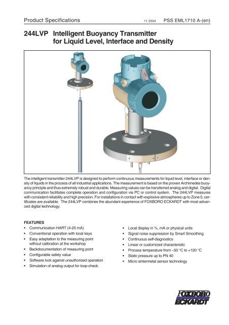
<strong>244LVP</strong> <strong>Intelligent</strong> <strong>Buoyancy</strong> <strong>Transmitter</strong><br />
<strong>for</strong> <strong>Liquid</strong> <strong>Level</strong>, <strong>Interface</strong> and Density<br />
The intelligent transmitter <strong>244LVP</strong> is designed to per<strong>for</strong>m continuous measurements <strong>for</strong> liquid level, interface or density<br />
of liquids in the process of all industrial applications. The measurement is based on the proven Archimedes buoyancy<br />
principle and thus extremely robust and durable. Measuring values can be transferred analog and digital. Digital<br />
communication facilitates complete operation and configuration via PC or control system. The <strong>244LVP</strong> measures<br />
with consistent reliability and high precision. For installations in contact with explosive atmospheres up to Zone 0, certificates<br />
are available. The <strong>244LVP</strong> combines the abundant experience of FOXBORO ECKARDT with most advanced<br />
digital technology.<br />
FEATURES<br />
• Communication HART (4-20 mA)<br />
• Conventional operation with local keys<br />
• Easy adaptation to the measuring point<br />
without calibration at the workshop<br />
• Backdocumentation of measuring point<br />
• Configurable safety value<br />
• Software lock against unauthorized operation<br />
• Simulation of analog output <strong>for</strong> loop-check<br />
• Local display in %, mA or physical units<br />
• Signal noise suppression by Smart Smoothing<br />
• Continuous self-diagnostics<br />
• Linear or customized characteristic<br />
• Process temperature from –50 °C to +120 °C<br />
• Static pressure up to PN 40<br />
• Micro sintermetal sensor technology
2 <strong>244LVP</strong> PSS EML1710 A-(en)<br />
TECHNICAL DATA<br />
Data refer to the sensor material Type 316L (1.4404)<br />
Explosion protection certificates must be observed!<br />
Input / Output<br />
Measuring ranges ........0...50 mm to 0...3 m<br />
upper and lower range value<br />
continuously adjustable<br />
Standard lenghts of<br />
Displacer (104DE) ........350..3000 mm, 14 .. 120 in;<br />
further lenghts on request<br />
Weight of displacer 1) ......max.25N<br />
Measuringspan..........2...20Ncontin.adjustable<br />
(to1Nonrequest)<br />
Span ratio<br />
Turn-down ..............1:1..1:10(1:20onrequest)<br />
Accuracy 2) .............± 0.2 % ; increased accuracy<br />
with customized adjustment<br />
Transferfunction .........linear or customized with up<br />
to 32 setpoints<br />
Configuration<br />
- with local push buttons and LCD<br />
- Digital (see communication ...)<br />
Local display ............LCD5digits, configurable in<br />
%, mA or phys. units<br />
Load .................R Bmax =(U S – 12V) / 23 mA<br />
Communication HART<br />
Connection .............Two-wiresystem<br />
Supply voltage U S :........12..42VDC 3) ,V SS 150 %,<br />
Data access failed,<br />
Over range > 110 %,<br />
Ambient temp. out of limits,<br />
Process temp. out of limits,<br />
Measuring range invalid<br />
1) For measurement of interface or density:<br />
25 N + buoyant <strong>for</strong>ce at lowest density<br />
2) Acc. ANSI / ISA - S51.1 - 1979<br />
3) With explosionproof device 12 .. 30 V
PSS EML1710 A-(en) <strong>244LVP</strong> 3<br />
Operating conditions 1)<br />
Processtemperature......–50°C...+120°C<br />
Pressure rating<br />
acc.toDIN............PN40<br />
acc.toANSI...........Class 150, 300<br />
Ambient temperature 2)<br />
without indicator ........–40°C...+85°C<br />
with LCD indicator .......–40°C...+70°C 3)<br />
Relative humidity .........
4 <strong>244LVP</strong> PSS EML1710 A-(en)<br />
Materials (Table of Comparison see page 6)<br />
Sensor<br />
Measuringcell...........316L (1.4404 / 1.4435)<br />
or Hastelloy C<br />
Fillfluid ................silicone oil<br />
Filling volume. ...........appox. 0.3 cm³<br />
Displacer 104DE .........316L (1.4404 / 1.4435),<br />
PTFE,<br />
PTFE with 25% carbon or<br />
Hastelloy C<br />
Suspension .............316L<br />
(1.4404 / 1.4435 / 1.4436)<br />
or Hastelloy C<br />
Connection flange ........316(1.4404 / 1.4571)<br />
Amplifier housing .........Aluminium<br />
(Alloy No GD-Al Si 12),<br />
Polyurethan coated, or<br />
Stainless Steel 316L (1.4404)<br />
For Sour Gas applications according to NACE Standard<br />
MR-0175-95:<br />
Diaphragm ............Hastelloy C<br />
Flange ...............316(1.4404 / 1.4571)<br />
Mounting<br />
Mounting method .........flange mounted<br />
acc.DIN..............DN50,DN80<br />
acc.ANSI.............2inchor3inch<br />
Weight<br />
<strong>Transmitter</strong> .............seetable page 6<br />
Displacer ...............seetable page 10<br />
Electrical connection<br />
Cableentrythread........M20x1.5or1/2-14NPT<br />
Cable gland and screwed sealing plug have to be ordered<br />
separately under model code BUSG ...<br />
For equipment in Ex d version, 1 screwed sealing plug<br />
made of stainless steel is included in delivery.<br />
Screw terminals ..........wirecross-section up to 2.5 mm²<br />
Testsockets ............Ø2mm<br />
Electromagnetic compatibility EMC<br />
Operating conditions ......industrialenvironment<br />
Immunity according to<br />
EN 61326 (3/2002) ......fulfilled<br />
Emission according to<br />
EN 61326 (3/2002) ......fulfilled<br />
EN 55011, May 2000,<br />
Group1,ClassA........fulfilled<br />
EN 61000-6-3 ..........fulfilled<br />
NAMUR recommendation Ne21 Status Aug.1998 fulfilled<br />
SAFETY REQUIREMENTS<br />
CE Label<br />
Electromagnetic compatibility . . 89/336/EWG<br />
Low-voltageregulation.....73/23/EWG<br />
Explosion protection. ......94/9/EG<br />
Safety<br />
According to EN 61010-1<br />
(resp. IEC 1010-1) ........safetyclassIII<br />
Internalfuses............none(ornotreplaceableby<br />
customer)<br />
Externalfuses ...........Limitationofpowersupplies<br />
<strong>for</strong> fire protection have to be observed due to EN 61010-1,<br />
appendix F (rsp. IEC 1010-1)
PSS EML1710 A-(en) <strong>244LVP</strong> 5<br />
Electrical classification ATEX<br />
1) 2)<br />
Intrinsic safe:<br />
AI 408 HART electronics II 2 G EEx ia/ib IIB/IIC T4 PTB 01 ATEX 2168 Zone 1<br />
mounted with:<br />
AI 419 C Sensor part <strong>244LVP</strong> II 1/2 G EEx ib/ia IIB T4..T6 PTB 01 ATEX 2044 Zone 0<br />
AI 419 D Sensor part <strong>244LVP</strong> II 1/2 G EEx ib/ia IIC T4..T6 PTB 01 ATEX 2044 Zone 0<br />
Explosion-proof:<br />
AD 931 Housing <strong>for</strong> HART II 2 G EEx d IIC T6 PTB 02 ATEX 1025 X Zone 1<br />
mounted with:<br />
AD 406 D Sensor part <strong>244LVP</strong> II 2 G EEx d IIC T6..T4 PTB 02 ATEX 1025 X Zone 1<br />
AD 406 C Sensor part <strong>244LVP</strong> II 2 G EEx d IIB T6..T4 PTB 02 ATEX 1025 X Zone 1<br />
Intrinsic safe and auxilliary protection:<br />
AID421 Housing <strong>for</strong> HART 1) II 2 G EEx ia d IIC T6 PTB 04 ATEX 2011 X Zone 1<br />
mounted with:<br />
AD 406 D Sensor part <strong>244LVP</strong> II 2 G EEx d IIC T6..T4 PTB 02 ATEX 1025 X Zone 1<br />
AD 406 C Sensor part <strong>244LVP</strong> II 2 G EEx d IIB T6..T4 PTB 02 ATEX 1025 X Zone 1<br />
Zone 2:<br />
AN 408 HART electronics II 3 G EEx ia/ib IIC T4 Certificated by Manufacturer Zone 2<br />
mounted with:<br />
AI 419 C Sensor part <strong>244LVP</strong> II 3 G EEx ib/ia IIB T4..T6 PTB 01 ATEX 2044 Zone 2<br />
Further National certificates<br />
- Overfill protection according to WHG<br />
International Certificates<br />
FM Certification<br />
Intrinsically Safe / I, II, III / 1 / ABCDEFG / T4 Ta=85°C<br />
Nonincendive /I/2/ABCD/T4Ta=85°C<br />
Special Protection / II / 2 /FG /T4 Ta=85°C<br />
Special Protection / III / 2 /T4 Ta=85°C<br />
Explosion proof/I/1/BCD/T6<br />
Dust-Ignitionproof / II, III / 1 / EFG / T6<br />
Type 4X<br />
Entity Parameters:<br />
Vmax=30 V, Imax=150 mA, Ci=2.45 nF, Li=0.14 mH<br />
CSA Certification<br />
Intrinsically safe / I, II, III / 2 / ABCDEFG /<br />
T3C Ta= 85 °C<br />
T4 Ta= 60 °C<br />
T4A Ta= 40 °C<br />
Type 4X<br />
Explosionproof / I, II, III / 1 / CDEFG / Ta= 85 °C<br />
Type 4X<br />
RUSSIAN “Intrinsic safety”<br />
RUSSIAN “Explosionproof”<br />
Belarus - Certificate Number 2176<br />
- Further protection types of on request -<br />
1) With appropriate order only<br />
2) National requirements have to be observed
6 <strong>244LVP</strong> PSS EML1710 A-(en)<br />
TABLE OF MATERIALS<br />
Comparison of Material<br />
Code WNr DIN Remarks equivalent to<br />
X6 CrNiMoTi 17 12 2 1.4571<br />
~ ASTM Typ 316Ti<br />
X2 CrNiMo 17 13 2 1.4404<br />
17 440<br />
X2 CrNiMo 18 14 3 1.4435<br />
ASTM Typ 316L<br />
X5 CrNiMo 17 13 3 1.4436<br />
NiMo 16 Cr 15 W 2.4819 17 744 equivalent to Hastelloy C-276 VdTÜV - Wbl. 400 UNS N 12 276<br />
GD - AlSi 12 3.2582.05 17 007 Al - Diecasting<br />
Service Limits <strong>244LVP</strong><br />
316 / 316L (1.4404 / 1.4571)<br />
Hastelloy C<br />
Nominal pressure Max. operating pressure in bar<br />
at temperature in °C<br />
–50 ... –10 –10 ... +50 +120<br />
PN 40 DIN 2635 40 40 35<br />
Class 150 19 18 16<br />
Class 300 49 49 42<br />
Table of Weights<br />
<strong>Transmitter</strong>,<br />
without displacer<br />
PN<br />
Weight [ kg ]<br />
Class<br />
40 150 300<br />
DN 50 / 2 inch 4.9 4.5 5.5<br />
DN 80 / 3 inch 7.2 7.4 9.2
PSS EML1710 A-(en) <strong>244LVP</strong> 7<br />
CONNECTIONS, OPERATIONAL ELEMENTS<br />
<br />
'<br />
"<br />
#<br />
$<br />
"<br />
!<br />
$<br />
# $<br />
%<br />
!<br />
<br />
# <br />
%<br />
<br />
1 Cover <strong>for</strong> terminal compartment<br />
2 Cable gland (as ordered)<br />
3 Plug, interchangable by Pos. 2<br />
4 External ground connection<br />
5 Internal ground connection<br />
6 Terminals(+/-)<br />
7 Test sockets Ø 2 mm integrated in terminals<br />
9 Security lock <strong>for</strong> EEx d version<br />
10 Cover <strong>for</strong> amplifier housing (with local display)<br />
12 Local key <strong>for</strong> lower range value / zero<br />
13 Local key <strong>for</strong> upper range value / damping<br />
14 LCD indicator<br />
15 Measuring variable<br />
16 Engineering unit<br />
17 Bottom housing cover<br />
50 Overvoltage protection (if present)
8 <strong>244LVP</strong> PSS EML1710 A-(en)<br />
MODEL CODES <strong>244LVP</strong><br />
<strong>Intelligent</strong> <strong>Buoyancy</strong> <strong>Transmitter</strong><br />
<strong>244LVP</strong><br />
with Displacer<br />
Flange Material: (Process wettet)<br />
316L 1.4404 1.4435. . . . . . . . . . . . . . . . . . . . . . -S<br />
Sensor Material: (Process Wetted)<br />
316L / 1.4435 / 1.4404 . . . . . . . . . . . . . . . . . . . . . . . . S<br />
316L / 1.4435 / 1.4404 with HC-Diaphragm . . . . . . . . . . . . . . N<br />
Flange Size<br />
DN50 . . . . . . . . . . . . . . . . . . . . . . . . . . . . . . . . . . . . 5<br />
DN80 . . . . . . . . . . . . . . . . . . . . . . . . . . . . . . . . . . . . 8<br />
2-Inch . . . . . . . . . . . . . . . . . . . . . . . . . . . . . . . . . . . . 2<br />
3-Inch . . . . . . . . . . . . . . . . . . . . . . . . . . . . . . . . . . . . 3<br />
Flange Pressure Rating & Contact Face<br />
PN40 (PN16 to PN40) C (a) . . . . . . (a). . . . . . . . . . . . . . . . . . . . C1<br />
PN160 (PN16 to PN40) N (a) . . . . . . (a). . . . . . . . . . . . . . . . . . . . N1<br />
PN250 (PN16 to PN40) E (a) . . . . . . (a). . . . . . . . . . . . . . . . . . . . E1<br />
ANSI Class 150 RF (b) . . . . . . . . . (b). . . . . . . . . . . . . . . . . . . . R1<br />
ANSI Class 300 RF (c) . . . . . . . . . (c). . . . . . . . . . . . . . . . . . . . R2<br />
ANSI Class 150 SF (b) . . . . . . . . . (b). . . . . . . . . . . . . . . . . . . . S1<br />
ANSI Class 300 SF (c) . . . . . . . . . (c). . . . . . . . . . . . . . . . . . . . S2<br />
ANSI Class 150 RJF (b). . . . . . . . . (b). . . . . . . . . . . . . . . . . . . . J1<br />
ANSI Class 300 RJF (c) . . . . . . . . . (c). . . . . . . . . . . . . . . . . . . . J2<br />
Version<br />
Base. . . . . . . . . . . . . . . . . . . . . . . . . . . . . . . . . . . . . . . . . . . . B<br />
Cable Entry<br />
M20x1.5 Without Cable Gland . . . . . . . . . . . . . . . . . . . . . . . . . . . . . . . . . . M<br />
1/2-14 NPT Without Cable Gland . . . . . . . . . . . . . . . . . . . . . . . . . . . . . . . . . N<br />
Communication:<br />
HART . . . . . . . . . . . . . . . . . . . . . . . . . . . . . . . . . . . . . . . . . . . . . . . . . . H<br />
Electrical Classification<br />
ATEXintrinsicsafe,Zone0-IIBT4. . . . . . . . . . . . . . . . . . . . . . . . . . . . . . . . . . . . . . . 0B4<br />
ATEXIntrinsicsafe,Zone0-IICT4 . . . . . . . . . . . . . . . . . . . . . . . . . . . . . . . . . . . . . . 0C4<br />
ATEXintrinsicsafe,Zone1-IICT4 . . . . . . . . . . . . . . . . . . . . . . . . . . . . . . . . . . . . . . 1C4<br />
ATEXintrinsicsafe,Zone1-IICT6 . . . . . . . . . . . . . . . . . . . . . . . . . . . . . . . . . . . . . . 1C6<br />
ATEXintrinsicsafe,Zone2-IICT4 . . . . . . . . . . . . . . . . . . . . . . . . . . . . . . . . . . . . . . 2C4<br />
ATEXintrinsicsafe,Zone1-IIBT6. . . . . . . . . . . . . . . . . . . . . . . . . . . . . . . . . . . . . . . 1B6<br />
ATEXexplosionproof,Zone1-IIBT6 . . . . . . . . . . . . . . . . . . . . . . . . . . . . . . . . . . . . . D1B<br />
ATEXexplosionproof,Zone1-IICT6 . . . . . . . . . . . . . . . . . . . . . . . . . . . . . . . . . . . . . D1C<br />
FM Nonincendive . . . . . . . . . . . . (d) . . . . . . . . . . . . . . . . . . . . . . . . . . . . . . . . . NFM<br />
FM Explosionproof . . . . . . . . . . . (d). . . . . . . . . . . . . . . . . . . . . . . . . . . . . . . . . . FDZ<br />
RUS Intrinsically Safe . . . . . . . . . . (d) . . . . . . . . . . . . . . . . . . . . . . . . . . . . . . . . . GAA<br />
CSA Explosionproof . . . . . . . . . . (d) . . . . . . . . . . . . . . . . . . . . . . . . . . . . . . . . . CDZ<br />
FM Intrinsically Safe . . . . . . . . . . . . . . . . . . . . . . . . . . . . . . . . . . . . . . . . . . . . . . FAA<br />
CSA Intrinsically Safe . . . . . . . . . . (d) . . . . . . . . . . . . . . . . . . . . . . . . . . . . . . . . . CAA<br />
For General Purpose Areas, Not Explosionproof . . . . . . . . . . . . . . . . . . . . . . . . . . . . . . . . ZZZ<br />
OPTIONS<br />
(continued on next page)
PSS EML1710 A-(en) <strong>244LVP</strong> 9<br />
MODEL CODES <strong>244LVP</strong> (continued)<br />
Options<br />
Custom Configuration . . . . . . . . . . . . . . . . . . . . . . . . . . . . . . . . . . . . . . . . . . . . . . . . . -T<br />
Tag No. Labeling<br />
Stamped With Weather Resistant Color . . . . . . . . . . . . . . . . . . . . . . . . . . . . . . . . . . . . . . . . -S<br />
Stainless Steel Label Fixed With Wire . . . . . . . . . . . . . . . . . . . . . . . . . . . . . . . . . . . . . . . . . -L<br />
Stainless Steel Label Fixed On Amplifier . . . . . . . . . . . . . . . . . . . . . . . . . . . . . . . . . . . . . . . . -F<br />
National Certificates<br />
Overfill Protection Per WHG Environmental Pollution . (d). . . . . . . . . . . . . . . . . . . . . . . . . . . . . . . -V<br />
Certificates<br />
EN 10204-2.1 (DIN 50 049-2.1), Certificate Of Compliance . . . . . . . . . . . . . . . . . . . . . . . . . . . . . . . -1<br />
EN 10204-2.3 (DIN 50 049-2.3), Specific Test Report (Calibration) . . . . . . . . . . . . . . . . . . . . . . . . . . . -2<br />
EN 10204-3.1B (DIN 50 049-3.1B), Inspection Certificate Of Process Wetted Material . . . . . . . . . . . . . . . . . -3<br />
PED 97/23/EC additional unit verification, according to module F/G . . . . . . . . . . . . . . . . . . . . . . . . . . . -4<br />
Comply With NACE Standard MR-01-75 (e) . . (e) . . . . . . . . . . . . . . . . . . . . . . . . . . . . . . . . . . -6<br />
EN 10204-3.1B (DIN 50 049-3.1B), Inspection Certificate Of Process Wetted Material<br />
with Copy of Original individual Material Certificate . . . . . . . . . . . . . . . . . . . . . . . . . . . . . . . . . . -9<br />
Footnotes<br />
a) Available with Flange Size 5 or 8<br />
b) Available with Flange Size 2 or 3<br />
c) Available with Flange Size 3<br />
d) Pending<br />
e) Only with Sensor Material N
10 <strong>244LVP</strong> PSS EML1710 A-(en)<br />
Displacer 104DE<br />
Standard Dimensions and Weights <strong>for</strong> Density Ranges ∆ρ 1)<br />
Material 316L (1.4404 / 1.4435) 2) PTFE /<br />
PTFE with 25 % C<br />
Hastelloy C<br />
<strong>Transmitter</strong><br />
Type<br />
-SD (PN 100) -ID 3) (PN 40 / 63) -SD (PN 250) -SD (PN 500) -SD (PN 100 / 160)<br />
Density Range ∆ρ<br />
<strong>244LVP</strong> 250 ... 1500 kg/m³ 100 ... 600 kg/m³ 400 ... 2000 kg/m³ 200 ... 1500 kg/m³ 300 ... 1500 kg/m³<br />
Model<br />
Code<br />
Len.<br />
L<br />
Ø<br />
mm<br />
Vol.<br />
cm³<br />
Wei.<br />
N<br />
PN<br />
bar<br />
Ø<br />
mm<br />
Vol.<br />
cm³<br />
Wei.<br />
N<br />
PN<br />
bar<br />
ρ min<br />
kg/m³<br />
Ø<br />
mm<br />
Vol.<br />
cm³<br />
Wei.<br />
N<br />
PN<br />
bar<br />
Ø<br />
mm<br />
Vol.<br />
cm³<br />
Wei.<br />
N<br />
PN<br />
bar<br />
Ø<br />
mm<br />
Vol.<br />
cm³<br />
Wei.<br />
N<br />
PN<br />
bar<br />
mm<br />
10 350 60.3 1000 19 100 101.6 2840 38 40 460 42.4 500 18 250 62 1056 23 500 60.3 1000 18 100<br />
11 500 48.3 920 17 100 88.9 3100 43 63 580 42.4 710 24 250 51 1021 23 500 48.3 920 19 100<br />
12 750 42.4 1060 21 100 76.1 3410 44 63 545 33.7 670 21 250 42 1039 24 500 48.3 1370 27 100<br />
13 1000 33.7 890 17 100 60.3 2855 41 63 545 26.9 570 18 250 35 961 21 500 33.7 890 19 100<br />
14 1200 33.7 1070 20 100 60.3 3425 48 63 675 26.9 680 22 250 35 1153 25 500 33.7 1070 22 100<br />
15 1500 26.9 850 16 100 51 3065 39 63 460 21.3 540 17 250 30 1060 24 500 26.9 850 18 160<br />
16 1800 26.9 1020 19 100 42.4 2540 38 63 495 21.3 640 20 250 28 1107 25 500 26.9 1020 21 160<br />
17 2000 26.9 1140 21 100 42.4 2825 41 63 565 21.3 710 22 250 25 981 22 500 26.9 1140 23 160<br />
18 2500 21.3 890 20 100 38 2840 37 63 425 17.2 580 16 250 22.5 993 23 500 21.3 890 23 160<br />
19 3000 21.3 1070 24 100 38 3400 45 63 575 17.2 700 23 250 20 942 22 500 21.3 1070 27 160<br />
inch<br />
20 14 60.3 1020 20 100 101.6 2885 38 40 455 42.4 510 18 250 62 1074 23 500 60.3 1020 18 100<br />
22 32 42.4 1150 23 100 76.1 3700 47 63 595 33.7 730 23 250 42 1126 26 500 33.7 720 16 100<br />
24 48 33.7 1090 20 100 60.3 3480 49 63 680 26.9 690 22 250 35 1171 26 500 33.7 1090 23 100<br />
25 60 26.9 870 16 100 51 3115 40 63 465 21.3 540 18 250 30 1076 24 500 26.9 870 18 100<br />
26 72 26.9 1040 19 100 42.4 2580 38 63 505 21.3 650 21 250 28 1124 26 500 26.9 1040 21 160<br />
27 84 26.9 1210 22 100 42.4 3000 44 63 635 21.3 760 23 250 25 1046 24 500 26.9 1210 25 160<br />
28 96 21.3 870 20 100 38 2765 37 63 420 17.2 570 16 250 22.5 968 22 500 21.3 870 23 160<br />
29 120 21.3 1090 25 100 38 3455 46 63 595 17.2 710 24 250 20 957 22 500 21.3 1090 25 160<br />
1) ∆ρ = ρ1-ρ2<br />
ρ1 = density of lower medium<br />
ρ2 = density of upper medium<br />
2) Using displacer material 1.4571 can cause small deviations in diameter, volume and weight.<br />
3) For measurement of interface or density, the max. density of the lower medium is 1350 kg/m³.<br />
If a Displacer Chamber is used, the difference between the diameter of the Displacer and the inside diameter of<br />
the Displacer Chamber must be at least 10 mm.<br />
Lengths < 350 mm and > 3000 mm, and density ranges < 100 kg/m³ and > 2000 kg/m³ on request.
PSS EML1710 A-(en) <strong>244LVP</strong> 11<br />
MODEL CODES 104DE<br />
Displacer Element<br />
104DE<br />
Density Range<br />
For 144LVD, <strong>244LVP</strong>, 144LD, 244L and 167LP<br />
Standard (Density Ranges see PSS) . . (b) . . . . . . . . . . . . . . . . -SD<br />
<strong>Interface</strong> (Density Ranges see PSS) . . (c) . . . . . . . . . . . . . . . . -ID<br />
Displacer Material<br />
316L (1.4404 / 1.4435 / 1.4571) (not available with Pressure Rating Code C) (a) . . S<br />
PTFE (<strong>for</strong> -SD only)<br />
(not <strong>for</strong> application in Zone 0 and Overfille Protection per VbF) . . . . . . . . . . P<br />
PTFE With 25% Carbon (<strong>for</strong> -SD only) (<strong>for</strong> application in Zone 0, IIA, IIB, IIC)<br />
(notwithdevice167LP). . . . . . . . . . . . . . . . . . . . . . . . . . . . . . O<br />
Hastelloy C (<strong>for</strong> -SD only) (not available with Pressure Rating Codes B, C) . (a) . . C<br />
Displacer Length "L"<br />
Standard <strong>for</strong> DIN<br />
Max Range<br />
350mm . . . . . . . . . . . . . . . . . . 0-350mm . . . . . . . . . . . . . . . . . 10<br />
500mm . . . . . . . . . . . . . . . . . . 0-500mm . . . . . . . . . . . . . . . . . 11<br />
750mm . . . . . . . . . . . . . . . . . . 0-750mm . . . . . . . . . . . . . . . . . 12<br />
1000 mm . . . . . . . . . . . . . . . . . 0-1000 mm . . . . . . . . . . . . . . . . . 13<br />
1200 mm . . . . . . . . . . . . . . . . . 0-1200 mm . . . . . . . . . . . . . . . . . 14<br />
1500 mm . . . . . . . . . . . . . . . . . 0-1500 mm . . . . . . . . . . . . . . . . . 15<br />
1800 mm . . . . . . . . . . . . . . . . . 0-1800 mm . . . . . . . . . . . . . . . . . 16<br />
2000 mm . . . . . . . . . . . . . . . . . 0-2000 mm . . . . . . . . . . . . . . . . . 17<br />
2500 mm . . . . . . . . . . . . . . . . . 0-2500 mm . . . . . . . . . . . . . . . . . 18<br />
3000 mm . . . . . . . . . . . . . . . . . 0-3000 mm . . . . . . . . . . . . . . . . . 19<br />
Standard <strong>for</strong> ANSI<br />
14-Inch. . . . . . . . . . . . . . . . . . . 0-14inch. . . . . . . . . . . . . . . . . . 20<br />
32-Inch. . . . . . . . . . . . . . . . . . . 0-32inch. . . . . . . . . . . . . . . . . . 22<br />
48-Inch. . . . . . . . . . . . . . . . . . . 0-48inch. . . . . . . . . . . . . . . . . . 24<br />
60-Inch. . . . . . . . . . . . . . . . . . . 0-60inch. . . . . . . . . . . . . . . . . . 25<br />
72-Inch. . . . . . . . . . . . . . . . . . . 0-72inch. . . . . . . . . . . . . . . . . . 26<br />
84-Inch. . . . . . . . . . . . . . . . . . . 0-84inch. . . . . . . . . . . . . . . . . . 27<br />
96-Inch. . . . . . . . . . . . . . . . . . . 0-96inch. . . . . . . . . . . . . . . . . . 28<br />
120-Inch . . . . . . . . . . . . . . . . . . 0-120inch . . . . . . . . . . . . . . . . . 29<br />
Intermediate Lengths . . . . . 0-3000 mm/0-120 inch (d) . . . . . . . . . . . . . . . . 30<br />
Suspension Length: (Dimension "b") (Specify exact length)<br />
UpTo0.99m/39Inches . . . . . . . . . . . . . . . . . . . . . . . . . . . . . . . . . . . . . 000<br />
1 m / 39.4 Inches To 3 m / 118.1 Inches . . . . . . . . . . . . . . . . . . . . . . . . . . . . . 003<br />
3 m / 118.1 Inches To 5 m / 196.8 Inches . . . . . . . . . . . . . . . . . . . . . . . . . . . . 005<br />
5 m / 196.8 Inches To 10 m / 394 Inches . . . . . . . . . . . . . . . . . . . . . . . . . . . . 010<br />
Suspension Material<br />
316L (1.4404 / 1.4435 / 1.4436) . . . . . . . . . . . . . . . . . . . . . . . . . . . . . . . . . . . . . S<br />
Hastelloy C . . . . . . . . . . . . . . . . . . . . . . . . . . . . . . . . . . . . . . . . . . . . . . . C<br />
Pressure Rating<br />
Up to PN 100/Class 600 (<strong>for</strong> interface Max PN 40/63) (Density ranges see PSS). . . . . . . . . . . . . . . . . A<br />
Up to PN 250/Class 1500 use only with 144LD, 244LD, 144LVD, <strong>244LVP</strong> and 167LP (Density ranges s. PSS) . B<br />
PN 500/Class 2500 use only with devices 144LVD and 167LP in Version -51 and -52 (Density ranges s. PSS) . C<br />
Options<br />
Damping Spring (Mat. 1.4301, Max. 250°C) . . . . . . . . . . . . . . . . . . . . . . . . . . . . . . . . . . . . . . -D<br />
Oxygen Service Cleaned . . . . . . . . . . . . . . . . . . . . . . . . . . . . . . . . . . . . . . . . . . . . . . . -O<br />
Additional Partition Point . . . . . . . . . . . . . . . . . . . . . . . . . . . . . . . . . . . . . . . . . . . . . . . . -X<br />
Tag No. Labeling<br />
Stamped With Weather Resistant Color . . . . . . . . . . . . . . . . . . . . . . . . . . . . . . . . . . . . . . . . -S<br />
Stainless Steel Label Fixed With Wire . . . . . . . . . . . . . . . . . . . . . . . . . . . . . . . . . . . . . . . . . -L<br />
Certificates<br />
EN 10204-2.1 (DIN 50 049-2.1), Certificate Of Compliance . . . . . . . . . . . . . . . . . . . . . . . . . . . . . . . -1<br />
EN 10204-3.1.B (DIN 50 049-3.1.B), Inspection Certificate Of Process Wetted Material . . (e) . . . . . . . . . . . . . -3<br />
(a) For application in Zone 0, IIA, IIB<br />
(b) Fluid Density, Pressure & Temp. required <strong>for</strong> calibration<br />
(c) Upper and Lower Fluid Density required <strong>for</strong> calibration<br />
(d) Length of Displacer in mm or inches required <strong>for</strong> manufacturing<br />
(e) Not with Displacer Material P or O
E % &<br />
' !<br />
% $<br />
<br />
" %<br />
12 <strong>244LVP</strong> PSS EML1710 A-(en)<br />
DIMENSIONS<br />
DN 50 and DN 80<br />
<br />
<br />
E<br />
% !<br />
& %<br />
'<br />
& #<br />
! ! #<br />
!<br />
"<br />
#<br />
#<br />
#<br />
$<br />
> <br />
E ! <br />
%<br />
&<br />
1 Connecting compartment cover<br />
2 Cable entry with screwed gland<br />
3 Amplifier housing<br />
4 Disconnection of sensor from the amplifier<br />
5 Connection flange (as per DIN / ANSI)<br />
6 Measuring cell<br />
7 Suspension<br />
8 Displacer 104DE<br />
9 Steel label with Tag.No.<br />
* Suited to the dimensions of<br />
FOXBORO ECKARDT - displacer,<br />
other lenghts on request<br />
** L (measuring range) see table page 10.
PSS EML1710 A-(en) <strong>244LVP</strong> 13<br />
OVERVIEW ACCESSORIES<br />
" " 8 2<br />
" . <br />
" , +<br />
" , -<br />
" * .<br />
For Displacer 104DE see page 10.<br />
For Displacer Chamber 104DC, Flange combination 104FK, Cover Flange Kit 104CF and Blanking Flange Kit<br />
104BF see Product Specifications PSS EML0900 A-(en), 104.. Accessories <strong>for</strong> <strong>Buoyancy</strong> <strong>Transmitter</strong>.<br />
Product Specifications <strong>for</strong> <strong>Intelligent</strong> <strong>Transmitter</strong>s<br />
PSS EMP0610 A-(en) 141GP <strong>Intelligent</strong> Gauge Pressure <strong>Transmitter</strong><br />
PSS EMP0620 A-(en) 142AP <strong>Intelligent</strong> Absolute Pressure <strong>Transmitter</strong><br />
PSS EMP0630 A-(en) 143DP <strong>Intelligent</strong> d/p <strong>Transmitter</strong><br />
PSS EML0610 A-(en) 144LD <strong>Intelligent</strong> <strong>Buoyancy</strong> <strong>Transmitter</strong> with Torque Tube<br />
<strong>for</strong> <strong>Liquid</strong> <strong>Level</strong>, <strong>Interface</strong> and Density<br />
PSS EML0710 A-(en) 244LD <strong>Intelligent</strong> <strong>Buoyancy</strong> <strong>Transmitter</strong> with Torque Tube<br />
<strong>for</strong> <strong>Liquid</strong> <strong>Level</strong>, <strong>Interface</strong> and Density<br />
PSS EML1610 A-(en) 144LVD <strong>Intelligent</strong> <strong>Buoyancy</strong> <strong>Transmitter</strong> <strong>for</strong> <strong>Liquid</strong> <strong>Level</strong>, <strong>Interface</strong> and Density<br />
PSS EML1710 A-(en) <strong>244LVP</strong> <strong>Intelligent</strong> <strong>Buoyancy</strong> <strong>Transmitter</strong> <strong>for</strong> <strong>Liquid</strong> <strong>Level</strong>, <strong>Interface</strong> and Density<br />
PSS EML2610 A-(en) 144FP <strong>Intelligent</strong> d/p <strong>Transmitter</strong> <strong>for</strong> <strong>Liquid</strong> <strong>Level</strong>, <strong>Interface</strong> and Density<br />
- Flange mounted<br />
PSS EML0900 A-(en) 104.. Accessories <strong>for</strong> <strong>Buoyancy</strong> <strong>Transmitter</strong>s<br />
PSS EMO0100 A-(en)<br />
Accessories <strong>for</strong> Devices with HART-Protocol
14 <strong>244LVP</strong> PSS EML1710 A-(en)<br />
Subject to alterations - reprinting, copying and translation prohibited. Products and publications are normally quoted<br />
here without reference to existing patents, registered utility models or trademarks. The lack of any such reference<br />
does not justify the assumption that a product or symbol is free.<br />
FOXBORO ECKARDT GmbH<br />
Postfach 50 03 47<br />
D-70333 Stuttgart<br />
Tel. # 49(0)711 502-0<br />
Fax # 49(0)711 502-597<br />
http://www.foxboro-eckardt.com DOKT 556 882 022


![[PSS 1-8A3 A] Model 84F Flanged Body Flowmeters; Model 84W ...](https://img.yumpu.com/33332673/1/190x245/pss-1-8a3-a-model-84f-flanged-body-flowmeters-model-84w-.jpg?quality=85)