SRD960 Universal Positioner SRD960-T Position Transmitter
SRD960 Universal Positioner SRD960-T Position Transmitter
SRD960 Universal Positioner SRD960-T Position Transmitter

Create successful ePaper yourself
Turn your PDF publications into a flip-book with our unique Google optimized e-Paper software.
Product Specifications 01.2006 PSS EVE0109 A-(en)<br />
<strong>SRD960</strong><br />
<strong>SRD960</strong>-T<br />
<strong>Universal</strong> <strong><strong>Position</strong>er</strong><br />
<strong>Position</strong> <strong>Transmitter</strong><br />
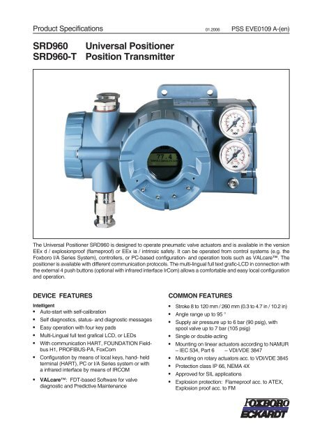
The <strong>Universal</strong> <strong><strong>Position</strong>er</strong> <strong>SRD960</strong> is designed to operate pneumatic valve actuators and is available in the version<br />
EEx d / explosionproof (flameproof) or EEx ia / intrinsic safety. It can be operated from control systems (e.g. the<br />
Foxboro I/A Series System), controllers, or PC-based configuration- and operation tools such as VALcare. The<br />
positioner is available with different communication protocols. The multi-lingual full text grafic-LCD in connection with<br />
the external 4 push buttons (optional with infrared interface IrCom) allows a comfortable and easy local configuration<br />
and operation.<br />
DEVICE FEATURES<br />
Intelligent<br />
• Auto-start with self-calibration<br />
• Self diagnostics, status- and diagnostic messages<br />
• Easy operation with four key pads<br />
• Multi-Lingual full text grafical LCD, or LEDs<br />
• With communication HART, FOUNDATION Fieldbus<br />
H1, PROFIBUS-PA, FoxCom<br />
• Configuration by means of local keys, hand- held<br />
terminal (HART), PC or I/A Series system or with<br />
a infrared interface by means of IRCOM<br />
• VALcare: FDT-based Software for valve<br />
diagnostic and Predictive Maintenance<br />
COMMON FEATURES<br />
• Stroke 8 to 120 mm / 260 mm (0.3 to 4.7 in / 10.2 in)<br />
• Angle range up to 95 °<br />
• Supply air pressure up to 6 bar (90 psig), with<br />
spool valve up to 7 bar (105 psig)<br />
• Single or double-acting<br />
• Mounting on linear actuators according to NAMUR<br />
– IEC 534, Part 6 – VDI/VDE 3847<br />
• Mounting on rotary actuators acc. to VDI/VDE 3845<br />
• Protection class IP 66, NEMA 4X<br />
• Approved for SIL applications<br />
• Explosion protection: Flameproof acc. to ATEX,<br />
Explosion proof acc. to FM
2 <strong>SRD960</strong> PSS EVE0109 A-(en)<br />
OVERVIEW<br />
- A ? JH E? I 8 A H I E I A A 2 $ <br />
0 0 ) 4 6 " ) <br />
. . N + , EC EJ= <br />
2 2 4 . 1* 7 5 2 )<br />
3 . 7 , ) 6 1 . EA @ > K I 0 <br />
2 '<br />
2 '<br />
2 <br />
2 <br />
) @ @ EJE = E 2 <br />
* E = HO E F K JI<br />
* E = HO K JF K JI<br />
2 I EJE BA A @ > = ? <br />
E EJI M EJ? D A I <br />
K JE C ) @ = F JA H I 2 %<br />
" & 2 6<br />
H/ "<br />
" 2 6<br />
H N #<br />
* I JA H I<br />
2 <br />
+ = > A / = @ I <br />
2 <br />
, EI F = O + L A H I 2 $<br />
+ , H - , H+ I A @<br />
> K EJE / = K C A I<br />
2 '<br />
Combinations<br />
Device version Controller Display local configuration remote configuration<br />
“H” HART (4-20) Digital LCD or 5 LEDs push buttons via communication<br />
“P” Profibus Digital LCD or 5 LEDs push buttons via communication<br />
“Q” F.Fieldbus Digital LCD or 5 LEDs push buttons via communication<br />
“F” FoxCom Digital LCD or 5 LEDs push buttons via communication
PSS EVE0109 A-(en) <strong>SRD960</strong> 3<br />
FUNCTIONAL SPECIFICATIONS (common data for all versions)<br />
Travel range<br />
Stroke range ............8to70mm(0.3to2.8in),<br />
and . . 60 to 120 mm (2.4 to 4.7 in),<br />
and . . 100 to 260 mm (3.9 to 10.2 in)<br />
Rotation angle range ......upto95°<br />
(without mechanical stop)<br />
Supply<br />
Supply air pressure .......1.4to6bar(20to90psig)<br />
with spool valve .......1.4to7bar(20to105psig)<br />
Outputtoactuator ........0to~100%ofsupply air<br />
pressure (up to 5.5 bar with 6<br />
bar supply pressure)<br />
Supply air. ..............according to ISO 8573-1<br />
For air supply we recommend to use the FOXBORO<br />
ECKARDT Filter regulator FRS923.<br />
1) 2)<br />
Response characteristic<br />
Sensitivity ..............
4 <strong>SRD960</strong> PSS EVE0109 A-(en)<br />
PHYSICAL SPECIFICATIONS (common data for all versions)<br />
Mounting (see page 17 for details)<br />
Attachment preparation by means of mounting adapter<br />
Option N for<br />
• NAMUR according to IEC 534, Part 6<br />
• Direct to IFC-/Flowserve actuators such as FoxPak<br />
and FoxTop<br />
• Rotary actuators according to VDI/VDE 3845<br />
Option R for<br />
• Rotary actuators according to VDI/VDE 3845<br />
Option T for<br />
• Integrated mounting with air connection on back<br />
- for details refer to page 23, Attachment prep.<br />
Option D for<br />
• NAMUR according to VDI/VDE 3847<br />
• Rotary actuators according to VDI/VDE 3845<br />
Attachment to stroke actuators<br />
- direct to FlowPak/FlowTop with attachment kit EBZG -E1<br />
- for casting yoke acc. to<br />
IEC 534-6 (NAMUR) .....withattachmentkitEBZG-H<br />
Stroke range<br />
with standard feedback lever EBZG-A: 8 to 70 mm<br />
with extended feedb. lever EBZG-B: 60 to 120 mm<br />
with extended feedb. lever EBZG-A1: 100 to 260 mm<br />
- for pillar yoke acc. to<br />
IEC 534-6 (NAMUR) .....withattachmentkitEBZG-K<br />
Stroke range<br />
with standard feedback lever ...8to70mm<br />
with extended feedback lever ...60to120mm<br />
Attachment to rotary actuators<br />
acc. to VDI/VDE 3845 ....withattachmentkitEBZG-R<br />
- Further attachment kits see ModelCodes page 21 -<br />
Materials<br />
Housingandcovers.......Aluminum(AlloyNo.230)<br />
finished with 2 component DD<br />
varnish<br />
All moving parts of<br />
feedback system (V4A) ....1.4306 / 1.4571 / 1.4104<br />
Mounting bracket .........Aluminum(AlloyNo.230)<br />
Pneumatic diaphragm Silicone (suitable for use in<br />
lacquer industry according to Lab-Test)<br />
Weight<br />
Singleacting ............approx.2.7kg(3.7lbs)<br />
Doubleacting............approx.3kg(4.4lbs)<br />
Pneumatic connection<br />
NAMURmounting........3xfemalethreads<br />
1/4-18 NPT or G1/4 for pipe diameter 6 to 12 mm (0.24<br />
to 0.47 in) for air supply and outputs y1, y2 to the actuator<br />
Directmounting..........Insteadoftheoutputy1<br />
an air connection on the backside with O-ring will be used<br />
(closed at NAMUR mounting).<br />
Electrical connection<br />
Line entry. ..............1or2cable glands<br />
M20 x1.5 or 1/2-14 NPT<br />
(others with Adapter AD-...)<br />
Cable diameter ..........6to12mm(0.24to0.47in)<br />
Screw terminals ..........2terminalsforinput,<br />
4 terminals for additional<br />
inputs/outputs<br />
Wire cross section 0.3 to 2.5 mm 2 (AWG 22-14)
PSS EVE0109 A-(en) <strong>SRD960</strong> 5<br />
Ambient conditions<br />
Operating conditions ......acc.toIEC654-1<br />
The device can be operated at a class Dx location<br />
Ambient temperature for<br />
Operation 1) ...........–40to80°C(–40to176°F)<br />
Transport and storage . . . –40 to 80 °C (–40 to 176 °F)<br />
Storage conditions acc.<br />
to IEC 60721-3-1: ......1K5;1B1;1C2; 1S3; 1M2<br />
Display<br />
LCD (visible) 2) ........–25to80°C(–13to176°F)<br />
LEDs...............–40to80°C(–40to176°F)<br />
Relative humidity .........upto100%<br />
Protection class<br />
acc.toIEC529.........IP66 3)<br />
acc.toNEMA..........Type4X<br />
Electromagnetic compatibility EMC<br />
Operating condititions: .....industriealenvironment<br />
Immunity according to<br />
- EN 61 326-1 ...........fulfilled<br />
Emission according to<br />
- EN 55 011,<br />
Group1,ClassB........fulfilled<br />
NAMUR<br />
recommendationNE21....fulfilled<br />
SAFETY REQUIREMENTS<br />
CE label<br />
Electromagnetic<br />
compatibility 4) ...........89/336/EWG<br />
Low-voltage regulation .....73/23/EWGnotapplicable<br />
Safety<br />
According to EN 61010-1<br />
(or IEC 1010-1) ..........safetyclassIII<br />
Overvoltage Category I<br />
Internalfuses............onlywithPROFIBUS or<br />
FONDATION Fieldbus,<br />
but not replaceable<br />
Externalfuses ...........limitationofpowersupplies<br />
for fire protection must be observed acc. to<br />
EN 61010-1, appendix F (or IEC 1010-1).<br />
Compliance with the essential health and safety<br />
requirements has been assured by compliance with<br />
EN 50014:1997 + A1 + A2 EN 50018:2000<br />
1) Details see Certificates of Conformity. With Option -T only –20 °C<br />
2) Below –20 °C reaction time for value changes is reduced<br />
3) Under service as directed<br />
4) With PROFIBUS or FOUNDATION Fieldbus only, if shield of wiring<br />
is grounded on both sides.
6 <strong>SRD960</strong> PSS EVE0109 A-(en)<br />
FUNCTIONAL SPECIFICATIONS<br />
Features<br />
Automaticstart-up........Autostartfunctionality<br />
Automatic detection of mechanical stops, control<br />
parameters and of direction of spring force. A dynamic<br />
optimization is included in this procedure. This procedure<br />
allows a full adaptation on optimi- zation of the positioner<br />
to the actuator without any manual adjustments!<br />
Options<br />
• Built-in independent inductive limit switches<br />
• Pressure Sensors for supply air pressure and output<br />
pressure I (y1) and II (y2)<br />
• Additional Inputs / outputs:<br />
• 2 binary outputs (position alarms)<br />
• <strong>Position</strong> feedback 4 to 20 mA + binary alarm output<br />
• 2 binary inputs<br />
Operation and configuration<br />
Local..................withfourkeys<br />
Display. ................Multi-Lingual Graphic LCD<br />
or five LEDs<br />
The positioner in LCD version is available with three<br />
different menu languages:<br />
Two menu languages are standard:<br />
- English<br />
- German<br />
Freely definable third language (additional languages on<br />
request):<br />
- French - Portuguese - Spanish<br />
- Italian - Swedish - etc.<br />
The third menu language has to be selected and specified<br />
with order.<br />
All additional Menu languages can be downloaded into the<br />
positioner by means of the operation- and configuration<br />
software VALcare. Additional language downloads are<br />
available on our homepage.<br />
<strong>Position</strong> feedback and alarms<br />
<strong>Position</strong> feedback / valve position . . via communication<br />
Optional 1) .............4to20mApositionfeedback<br />
Alarms.................viacommunication<br />
Optional 1) .............1alarm output<br />
<strong>Position</strong>alarms ..........viaKommunikation<br />
Hi and Lo alarm<br />
Hi/Hi and Lo/Lo alarm<br />
Optional 1) .............2binary outputs<br />
Hi and Lo alarm<br />
Hi/Hi and Lo/Lo alarm<br />
Independent feedback:<br />
Limit switch (inductive) .....Standard version<br />
Security version<br />
(common data for all versions)<br />
Diagnosis<br />
– local<br />
• Self diagnostics<br />
• Status- and diagnostic messages<br />
– via VALcare Valve Diagnostic Software:<br />
• Service Management for planning and scheduling of<br />
service intervals<br />
• Histograms for displaying the position- and response<br />
history over time<br />
• Partial Stroke Test for the functional inspection of safety<br />
related actuators<br />
• Hours in operation, cycle counter and travel sum of<br />
the actuator are determined<br />
• Surveillance of loop current<br />
• shows condition of device:<br />
- Potentiometer<br />
-IPMotor<br />
- exceeding range of actuator (possible indication for<br />
wear of plug or seat)<br />
- remaining control deviation (possible indication for<br />
jammed actuator, blocked valve stem or plug, not<br />
sufficient air capacity /supply air pressure /positioning<br />
pressure)<br />
• if equipped with pressure sensors (optional):<br />
• Monitoring of the stem friction<br />
• Histograms for displaying the friction-history<br />
over time<br />
• surveillance of air supply and output pressure,<br />
each with display of physical value<br />
• Additional diagnostical possibilities in control<br />
operation by means of external sensors (optional).<br />
See also the VALcare Documentation.<br />
Service plug and IrCom<br />
All basic devices (except FoxCom version before HW rev.3)<br />
are equipped with a service plug at the front side. There via<br />
RS232 interface a PC with VALcare (FDT Software) can<br />
be connected via modem EDC82 (galv. separated, not Ex).<br />
If the SRD is equipped with option “IrCom”, communication<br />
can take place contactless via infrared with the positioner<br />
(even with a closed cover!). Modem “IR Interface” (not Ex)<br />
is connected via RS232 interface to a PC (for practical<br />
reasons a notebook) with VALcare (FDT software) and<br />
makes possible a range of approx. 1 m.<br />
(If the notebook has an IrDa interface, this cannot be used,<br />
despite similar technique. The IrDa instruction set has no<br />
communication commands for positioners.-)<br />
1) By means of additional inputs/outputs (Option Board)
PSS EVE0109 A-(en) <strong>SRD960</strong> 7<br />
Manual settings:<br />
Actuatormode...........linear or rotary actuator<br />
Linear valve ...........leftorright mounted<br />
Rotaryactuator.........opening clockwise or<br />
counter-clockwise<br />
Characteristic of setpoint . . . linear, equal percentage,<br />
invers- equal percentage<br />
or custom (22 points)<br />
Valvefunction ...........opens or closes with<br />
increasing setpoint<br />
Split range .............freeupper and lower values<br />
Travellimits.............freeupper and lower values<br />
Cutoffs.................freeupper and lower values<br />
Stroke range ............configurable<br />
Temperature unit .........configurable (°C or °F)<br />
Autostart ...............-Endpoints<br />
- Standard Autostart<br />
- Enhanced Autostart 1)<br />
- Smooth response 1)<br />
- Fast response 1)<br />
Control parameters .......Determined during Autostart.<br />
Working range ...........freely adjustable (for indication<br />
on LCD<br />
Manual adjustment of. .....P-gain, I-time,<br />
T63-time and dead band<br />
Manual operation .........Manual input of setpoint to<br />
drive the valve in steps with<br />
12.5 % or 1 % 1)<br />
Pneumatic test ...........Functiontotestthepneumatic<br />
output<br />
Workshop ..............input and angle calibation<br />
LCD language ...........dependent on version<br />
LCD orientation ..........dependent on version<br />
PROFIBUS-PA ..........Busaddress<br />
FOUNDATION Fieldbus ...Simulation<br />
Switch from Link Master to<br />
Basic Field Device<br />
Software supported configurations:<br />
- by means of Hand Held Terminal (HART)<br />
- PC by means of VALcare Software<br />
- I/A Series System and other DCSs<br />
- Depending on the version, configurations can be achieved<br />
by a non-contact, protocol-independent infrared<br />
interface by means of IRCOM.<br />
Failure handling<br />
Safety position at<br />
-Airsupplyfailure ........pressurey1=zero<br />
- Electric power failure .....pressurey1=zero<br />
- Failure of electronics .....pressurey1=zero<br />
- Failure of communication is recognized by configurable<br />
watch dog with response delay of 0.1 s to 24 h<br />
behavior. ...............configurable as<br />
pressure y1 = zero or<br />
stop at last value or<br />
a configured value<br />
Diagnostic report .........viacommunication and local<br />
LCD<br />
-historicalstatus .........issetifalarm was activated at<br />
any time (also just short alarms)<br />
Reset..................byacknowledging<br />
1) from HW-Rev. 3.4 / Firmware Rev. 16
8 <strong>SRD960</strong> PSS EVE0109 A-(en)<br />
4) 5)<br />
Electrical Classification<br />
See certificate of conformity EX EVE0109 A (de)(en)<br />
Type of protection ATEX “EEx d – Flameproof”<br />
II 2 G EEx d IIC Temperature class T4...T6<br />
(Design AD 639)<br />
EC-Type-Examination Certificate PTB 02 ATEX 1084 X<br />
Permissible ambient temperature range:<br />
TemperatureclassT4 .....–30°Cto+80°C<br />
(–22 °F to 176 °F)<br />
TemperatureclassT4 .....(onrequest)<br />
–40 °C to +80 °C<br />
(–40 °F to 176 °F)<br />
TemperatureclassT6 .....–30°Cto+75°C<br />
(–22 °F to 167 °F)<br />
TemperatureclassT6 .....(onrequest)<br />
–40 °C to +75 °C<br />
(–40 °F to 167 °F)<br />
For connections in explosion protected hazardous areas<br />
according to directive 94/9/EG appendix II, with the<br />
following maximum values:<br />
Input circuit:<br />
Maximum electrical power . P max = 2.5 W<br />
Electrical connections ..........Umax=upto60V<br />
Self-heating of device surface ....1.3K/W<br />
Type of protection FM “explosion proof”<br />
Class I Division 1, Groups B, C, D<br />
hazardous locations, indoor and outdoor, NEMA 4X<br />
4) With appropriate order only<br />
5 National requirements must be observed
PSS EVE0109 A-(en) <strong>SRD960</strong> 9<br />
BASIC DEVICE with<br />
communication HART<br />
Signal Input<br />
Two wire system<br />
Reverse polarity protection. . feature<br />
Signal range ............4to20mA<br />
Operating range. .........3.6to21.5mA<br />
Voltage range of unloaded<br />
input signal .............12to48V<br />
Load ..................420Ohms,8.4Vat20mA<br />
Communication signal .....HART,1200 Baud, FSK<br />
(Frequency Shift Key)<br />
modulated on 4 to 20 mA<br />
0.5 Vpp at 1kOhm load<br />
Input impedance Zi. .......Z=320Ohms<br />
for ac voltage 0.5 to 10 kHz with < 3 dB non-linearity<br />
Cable capacity and inductance see HART standard<br />
specifications. (e.g. C < 100 nF).<br />
Impedance of other devices at the input (parallel or serial)<br />
must be within HART spec.<br />
Applications without communication require not to exceed<br />
input capacitance parallel to the input not higher than 100 µF.<br />
Start-up time (init phase) . . . approx. 2 sec<br />
Interruption time without power down:<br />
-withLCD..............85ms 1)<br />
-withLED..............75ms 1)<br />
Configuration<br />
Local / Display ...........seepage 6<br />
Software ...............VALcare(FDT-Software)<br />
Hardware. ..............Modem MOD991 for PC, IBM<br />
compatible<br />
Hand Terminal ...........HARTHandheld terminal<br />
I/A Series System ........onrequest<br />
Other control systems .....AMS, Siemens SIMATIC PDM<br />
(ProcessDeviceManager)<br />
BASIC DEVICE with<br />
communication FoxCom(digital)<br />
Signal Input<br />
Two wire system<br />
Reverse polarity protection. . feature<br />
Input ..................digital<br />
voltage range of supply input DC 8 to 48 V<br />
Supply current ...........approx. 9 mA at DC 24 V<br />
Communication signal .....FoxComdigital,4800Baud,<br />
FSK (Frequency Shift Key)<br />
modulated on supply voltage<br />
0.5Vpp at 500 Ohms load.<br />
Input impedance .........Z=500Ohms<br />
(for ac voltage 3 kHz to 15 kHz)<br />
Start-up time (init phase) approx. 2 sec<br />
Interruption time without power down:<br />
-withLCD..............85ms 1)<br />
-withLED..............75ms 1)<br />
Configuration<br />
Local/Display...........seepage6<br />
Software ...............VALcare(FDT-Software)<br />
Hardware...............Modem PC10<br />
I/A Series System ........FBM43,FBM243, 246 2)<br />
in connection with CP60<br />
Electrical classification hereto:<br />
seePage8<br />
Electrical classification hereto:<br />
see Page 8<br />
1) Worst case conditions 4-20mA, with position feedback option, i/p-output<br />
with max. current
10 <strong>SRD960</strong> PSS EVE0109 A-(en)<br />
BASIC DEVICE with<br />
communication PROFIBUS-PA and FOUNDATION Fieldbus H1<br />
PROFIBUS-PA<br />
Datatransfer............according to PROFIBUS- PA<br />
profile class B based on EN<br />
50170 and<br />
DIN 19245 part 4<br />
GSDfile................theactualfilecanbedownloaded<br />
from our homepage<br />
Configuration<br />
Local / Display ...........seepage 6<br />
Software ...............VALcare(FDT-Software)<br />
Hardware. ..............PC-orPCMCIA-interfaces<br />
from Softing<br />
I/A Series System ........withFBM223<br />
Other control systems .....AllProfibus-PA- compatible,<br />
e.g. Siemens SIMATIC PDM<br />
(ProcessDevice Manager)<br />
FOUNDATION Fieldbus H1<br />
Datatransfer............according to Fieldbus<br />
FOUNDATION Specification<br />
Rev. 1.4, Link-Master (LAS).<br />
FunctionBlocks..........AO,Transducer,Resource,<br />
PID<br />
DD files ................theactualfilecanbedownloaded<br />
from our homepage<br />
Configuration<br />
Local / Display ...........seepage 6<br />
Software ...............VALcare(FDT-Software)<br />
or National Instruments<br />
NI-FBUS configurator<br />
Hardware. ..............FBUS-interfaces(AT-FBUS<br />
and PCMCIA- FBUS)<br />
I/A Series System ........withFBM220/221<br />
Other control systems .....AllFieldbus FOUNDATION<br />
H1-compatible.<br />
Fisher Rosemount Delta-V,<br />
Honeywell, Yokogawa, ABB<br />
For both fieldbus versions<br />
Input signal .............digital<br />
Supply voltage ...........DC9to32V*)<br />
max. Supply voltage. ......DC48V<br />
Operatingcurrent.........10.5mA±0.5<br />
(base current)<br />
Current amplitude ........±8mA<br />
Faultcurrent.............basecurrent+0mA<br />
(base current + 4 mA by means of independent<br />
FDE-safety circuit) according to IEC 1158-2<br />
Start-up time (init phase) ...approx.2sec<br />
Operating values<br />
Busconnection ..........Fieldbusinterfacebased<br />
on IEC 1158-2 according to FISCO-Model<br />
(see Electrical certifications)<br />
Powersupply............Powersupply is achieved<br />
dependant on the application by means of fieldbus<br />
power supply units or segment coupler<br />
Electrical classification hereto:<br />
seePage8<br />
*) Data of ”Intrinsically Safe” version
PSS EVE0109 A-(en) <strong>SRD960</strong> 11<br />
BASIC DEVICE as<br />
<strong>Position</strong> <strong>Transmitter</strong> <strong>SRD960</strong>-T (<strong>SRD960</strong>-TXQSSX6EDZNS)<br />
- <strong>Position</strong> feedback device without pneumatic components -<br />
Input .................Stroke/Rotaryangle by<br />
means of conductive<br />
plastic precision<br />
potentiometer<br />
Output ................Twowiresystem<br />
Signal range ............4to20mA/20to4mA<br />
or free configuration<br />
3.3 to 23.5 mA<br />
Permitted load ...........R bmax = (Us–12 V) / 0.02 A [Ω]<br />
(Us = supply voltage)<br />
Power supply<br />
Reverse polarity protection. . standard feature<br />
Supply voltage ...........Us=DC12to36V<br />
Permitted ripple ..........
12 <strong>SRD960</strong> PSS EVE0109 A-(en)<br />
ADDITIONAL EQUIPMENT for all versions.<br />
Additional Inputs / Outputs, built into basic device<br />
Order in Model Code: <strong>SRD960</strong>–ooýoooooooo Order in Model Code: <strong>SRD960</strong>–ooýoooooooo<br />
Two binary outputs (limit signals) [item 1]<br />
Stroke / angle derivated from positioner feedback,<br />
configurable<br />
galvanically separated 2 limit signals, two-wire system,<br />
according to DIN 19234, for external supply<br />
supply voltage ..........DC8to48V<br />
Logic:<br />
limit value not exceeded ...2.2mA (typ.6mA)<br />
device fault ...........40mA/10V<br />
(power derated)<br />
Reference: AB1 for upper, AB2 for lower limit<br />
Terminals for AB1 ........81+,82–<br />
AB2 83+, 84–<br />
Explosion protection hereto see page 15.<br />
Parts set for subsequent mounting:<br />
Code P ................EW426346021<br />
<strong>Position</strong> feedback 4 to 20 mA [item 2]<br />
Stroke / angle derivated from positioner feedback,<br />
1 output analog, galvanically separated, two-wire system<br />
according to DIN 19234, for external supply<br />
supplyvoltage..........DC8to48V<br />
signal range ...........3.8to21.5mA<br />
0 % and 100 % configurable<br />
devicefault............
PSS EVE0109 A-(en) <strong>SRD960</strong> 13<br />
ADDITIONAL EQUIPMENT<br />
(continued)<br />
Additional Inputs / Outputs, built into basic device<br />
Order in Model Code: <strong>SRD960</strong>–ooýoooooooo Order in Model Code: <strong>SRD960</strong>–ooooooooooý<br />
Two Binary inputs [item 3]<br />
Two independent binary inputs, supplied by the basic<br />
device, for connection of sensors. A connected switch is<br />
loaded with 3 V, 150 µA.<br />
Both binary inputs can be used for diagnostics or also<br />
configurable for the control functions.<br />
Switch 1 Switch 2 Actuator control function<br />
close close normal operation<br />
open close go to stop at 0 %<br />
close open go to stop at 100 %<br />
open open hold last position<br />
Terminals for EB1 ........13+,14–<br />
EB2 ........15+,16–<br />
Requirements for connected switches:<br />
Capacitance in parallel .....10kOhms<br />
Hysteresis..............2to5kOhms<br />
For application with .......-mechanical switches<br />
- opto couper outputs<br />
- open collector / drain<br />
outputs of transistor<br />
circuits<br />
Pressure sensors [item 5]<br />
Three built-in pressure sensors, Code "Option" – B,<br />
suitable for versions with communication<br />
For supply air, output y1 and y2 to actuator<br />
Measuringrange.........0to8bar(0to120psig)<br />
Accuracy ...............0.5%<br />
Temperature influence .....0.5%/10k(–40to80°C)<br />
Parts set for subsequent mounting: –<br />
Explosion protection hereto see page 15.<br />
Parts set for subsequent mounting:<br />
Code B ................EW426346012<br />
Option “Built-in pressure sensors”<br />
#
14 <strong>SRD960</strong> PSS EVE0109 A-(en)<br />
ADDITIONAL EQUIPMENT<br />
(continued)<br />
For all versions. Built into basic device<br />
Order in Model Code: <strong>SRD960</strong>–ooýoooooooo<br />
Built-in Limit Switch [item 4]<br />
Inductive Limit Switch<br />
standard version (SJ2-N) . . . . . . Code T<br />
security version (SJ2-SN). . . . . . Code U<br />
- in three wire technology<br />
(SI 2-K08-AP7). .......... . . Code R<br />
Stroke / angle derivated from positioner feedback,<br />
two-wire system<br />
Output.................2inductive proximity sensors<br />
acc. to DIN 19 234 or NAMUR for connection to<br />
switching amplifier with intrinsically safe control circuit 1)<br />
Current consumption<br />
vane clear .............>2.2mA<br />
vaneinterposed.........
PSS EVE0109 A-(en) <strong>SRD960</strong> 15<br />
ADDITIONAL EQUIPMENT (continued)<br />
For all versions. Built into basic device<br />
Security version ”U”<br />
CE label<br />
Electromagnetic compatibility 89/336/EWG<br />
Low-voltage regulation...73/23/EWGnotapplicable<br />
Safety<br />
According to EN 61010-1<br />
(or IEC 1010-1) ..........SafetyClass III<br />
Overvoltage Category I<br />
Internalfuses............notreplaceable<br />
Externalfuses ...........limitationofpower supplies<br />
for fire protection must be observed acc. to<br />
EN 61010-1, appendix F (or IEC 1010-1)<br />
Compliance with the essential health and safety<br />
requirements has been assured by compliance with<br />
EN 50014:1997 + A1 + A2 EN 50018:2000<br />
1) 2)<br />
Electrical Classification<br />
See certificate of conformity EX EVE0109 A (de)(en)<br />
Type of protection ATEX “EEx d – Flameproof”<br />
II 2 G EEx d IIC Temperature class T4...T6<br />
(Design AD 639)<br />
EC-Type-Examination Certificate PTB 02 ATEX 1084 X<br />
Permissible ambient temperature range:<br />
TemperatureclassT4 .....–30°Cto+80°C<br />
(–22 °F to 176 °F)<br />
TemperatureclassT4 .....(onrequest)<br />
–40 °C to +80 °C<br />
(–40 °F to 176 °F)<br />
TemperatureclassT6 .....–30°Cto+75°C<br />
(–22 °F to 167 °F)<br />
TemperatureclassT6 .....(onrequest)<br />
–40 °C to +75 °C<br />
(–40 °F to 167 °F)<br />
For connections in explosion protected hazardous areas<br />
according to directive 94/9/EG appendix II, with the<br />
following maximum values:<br />
Input circuit:<br />
Maximum electrical power . P max = 2.5 W<br />
Electrical connections ..........Umax=upto60V<br />
Self-heating of device surface ....1.3K/W<br />
Type of protection ATEX “Intrinsic safety“ *)<br />
II 2 G EEx ia IIC Temperature class T4...T6<br />
(Elektronics family Type xxx)<br />
Permissible ambient temperature range:<br />
TemperatureclassT4 .....–40°Cto+80°C<br />
(–40 °F to 176 °F)<br />
TemperatureclassT6 .....–40°Cto+75°C<br />
(–40 °F to 167 °F)<br />
Type of protection FM “explosion proof”<br />
Class I Division 1, Groups B, C, D<br />
hazardous locations, indoor and outdoor, NEMA 4X<br />
Type of protection FM “Intrinsic Safety” *)<br />
Class I Division 1, Groups A, B, C, D<br />
Class II Division 1, Groups E, F, G<br />
Class III Division 1 in acc. with entity requirements<br />
hazardous locations, indoor and outdoor, NEMA 4X<br />
Type of protection CSA “explosion proof” *)<br />
Class I Division 1, Groups B, C, D<br />
hazardous locations, indoor and outdoor, NEMA 4X<br />
Type of protection CSA “Intrinsic Safety” *)<br />
Class I Division 1, Groups A, B, C, D<br />
Class II Division 1, Groups E, F, G<br />
Class III Division 1 in acc. with entity requirements<br />
hazardous locations, indoor and outdoor, NEMA 4X<br />
*) In preparation<br />
1) In corresponding version<br />
2) National directives have to be observed
16 <strong>SRD960</strong> PSS EVE0109 A-(en)<br />
LOCAL DISPLAY<br />
Order in Model Code: <strong>SRD960</strong>–oooýoooooýo<br />
There are three Display covers available:<br />
• Cover with LCD and 4 external push buttons<br />
• Cover with 5 LEDs and 4 external push buttons<br />
• Cover, solid, without window; internal push buttons<br />
The positioner in version with LCD is available with three<br />
different menu languages:<br />
Standard menu languages:<br />
- English - German<br />
Freely definable third language (additional languages on<br />
request):<br />
- French - Portuguese - Spanish<br />
- Italian - Swedish - see ModelCode<br />
The third menu language has to be selected and specified<br />
with order.<br />
The pre-set menu language is English. This menu language<br />
can easily be set to another pre-configured menu language<br />
by means of the local push buttons.<br />
All “freely definable” third Menu languages can be downloaded<br />
into the positioner by means of the operation- and<br />
configuration software VALcare. This way also the preconfigured<br />
third language can be modified. The additional<br />
language downloads are available on our homepage.<br />
Despite some special functions all configurable parameters<br />
are accessible by means of the local push buttons.<br />
Displayed data<br />
in operation:<br />
• valve position<br />
• stem position<br />
• input current<br />
• setpoint digital<br />
• setpoint stem<br />
• supply pressure<br />
• output pressure 1<br />
• output pressure 2<br />
• temperature<br />
• valve cycles<br />
• travel sum<br />
• Hours of operation<br />
• Tag number<br />
• Tag name<br />
• Firmware version<br />
Configuration<br />
Main Menus:<br />
• 1: attachment<br />
• 2: autostart<br />
• 3: valve function<br />
• 4: characteristics<br />
• 5: limits / alarms<br />
• 6: parameters<br />
• 7: pneumatic output<br />
• 8: manual setting of valve<br />
position<br />
• 9: calibration / workshop<br />
• 10:Bus Address/Simulation<br />
(Profibus PA / F.Fieldbus)<br />
With LED display the configuration functionallity is the same<br />
as with LCD (but LCD is easier to use).<br />
Details see Master Instructions or Quick Guide.<br />
LCD Cover<br />
LED Cover<br />
Local Push buttons:<br />
Value<br />
What is displayed<br />
Status and diagnostic message<br />
Configuration Menus<br />
LCD orientation can be changed<br />
by means of local push<br />
buttons under Menu 9.9<br />
MENU DOWN UP ENTER
PSS EVE0109 A-(en) <strong>SRD960</strong> 17<br />
ATTACHMENT PREPARATION<br />
Order in Model Code: <strong>SRD960</strong>–ooooooooýoo<br />
The <strong>Universal</strong> <strong><strong>Position</strong>er</strong> needs a linking piece for attachment<br />
to the different brands of actuators.<br />
The standard Mounting Adapter is marked with Option N.<br />
Mounting Adapter<br />
Preparation for attachment to:<br />
• NAMUR, according to IEC 534-6<br />
• Direct mounting to FoxPak and FoxTop actuators, with<br />
y1-d air supply (no external tubing for y)<br />
• Rotary actuators acc. to VDI/VDE 3845<br />
Order Option N.<br />
<br />
Preparation for attachment to:<br />
• Rotary actuators acc. to VDI/VDE 3845<br />
Order Option R.<br />
4<br />
Preparation for attachment to:<br />
• Integrated mounting with air connections on rear<br />
• Rotary actuators acc. to VDI/VDE 3845<br />
Order Option T.<br />
6<br />
Preparation for attachment to:<br />
• NAMUR, according to VDI/VDE 3847<br />
• Rotary actuators acc. to VDI/VDE 3845<br />
Order Option D.<br />
,<br />
Option F<br />
as Option N, but no y1-d air supply (with external tubing<br />
for y)
18 <strong>SRD960</strong> PSS EVE0109 A-(en)<br />
FUNCTIONAL DESIGNATIONS<br />
#<br />
!<br />
<br />
! =<br />
<br />
<br />
=<br />
&<br />
<br />
'<br />
"<br />
! =<br />
! > ! ?<br />
! @<br />
=<br />
&<br />
#<br />
$<br />
%<br />
$<br />
#<br />
<br />
<br />
'<br />
$<br />
1 Cable gland 1)<br />
2 Plug, interchangeable with Pos. 1 1)<br />
3 Connection 2) (11 +/12 –) for input (w) or<br />
terminals (11 / 12) for bus connection IEC 1158-2<br />
3a Connection 2) for additional inputs / outputs<br />
4 Ground connection<br />
5 Female thread G ¼ or ¼-18 NPT 3) for output I (y1)<br />
6 Female thread G ¼ or ¼-18 NPT 3) for air supply (s)<br />
7 Female thread G ¼ or ¼-18 NPT 3) for output II (y2)<br />
8 Direct attachment hole for output I (y1)<br />
9 Feedback shaft<br />
10 Connection manifold for attachment to stroke actuators<br />
(see page 17 for details)<br />
11 Connection base for attachment to rotary actuators<br />
12 Cover with window and push buttons<br />
12a Push button protection cover (option -X)<br />
13a Key ΠMENU<br />
13b Key – DOWN<br />
13c Key + UP<br />
13d Key ! ENTER / STORE<br />
15 pneumatic unit with amplifier and connection<br />
16 4 screws for connection of pneumatic unit<br />
18 built-in pressure gauges for air-supply, output Y1<br />
and output Y2<br />
19 Cover for electronic connection compartment<br />
20 Protection screw for electronic connection- and<br />
electronic compartment<br />
21 Air vent, dust and water protected<br />
(IP65 and NEMA 4X)<br />
22 Data label<br />
25 Tip jacks, 2 mm dia.<br />
26 Arrow is perpendicular to shaft 9 at angle 0 degree<br />
1) See cable glands BUSG on page 27. The device is supplied with dust<br />
protection covers<br />
2) Screw terminals or WAGO Cage clamps<br />
3) Type of thread marked on housing
PSS EVE0109 A-(en) <strong>SRD960</strong> 19<br />
Model Codes <strong>SRD960</strong><br />
<strong>Universal</strong> <strong><strong>Position</strong>er</strong> <strong>SRD960</strong> 201205<br />
Version<br />
Single Acting . . . . . . . . . . . . . . . . . . . . -B<br />
Double Acting . . . . . . . . . . . . . . . . . . . -C<br />
<strong>Position</strong> <strong>Transmitter</strong> (w/o pneumatic components) . -T<br />
Input / Communication<br />
Intelligent without Communication (4-20 mA) . . . (a)(g) . D<br />
HART(4-20mA). . . . . . . . . . . . . . . . . . (g). . H<br />
FoxCom (Digital) . . . . . . . . . . . . . . . . . . (g) . . F<br />
Profibus PA based on IEC 1158-2 (MBP)<br />
according to FISCO (Fieldbus) . . . . . . . . . . (g). . P<br />
FOUNDATION Fieldbus H1 based on IEC 1158-2 (MBP)<br />
according to FISCO (Fieldbus) . . . . . . . . . . (g). . Q<br />
(not applicable) . . . . . . . . . . . . . . . . . . . (f) . . X<br />
Additional Inputs / Outputs<br />
Without Additional Inputs / Outputs . . . . . . . . . (g). . . . . . N<br />
Binary Input - integrated . . . . . . . . . . . . . . (g). . . . . . B<br />
Binary Output - integrated . . . . . . . . . . . . . (g). . . . . . P<br />
Analog <strong>Position</strong> Feedback (4-20 mA) . . . . . . . . . . . . . . . Q<br />
- integrated and connected as Option Board . . . . (g)<br />
- stand alone feedback unit. . . . . . . . . . . . . (f)<br />
Limit Switches (standard version SJ2-N) . . . . . . (g). . . . . . T<br />
LimitSwitches(securityversionSJ2-SN). . . . . . (g). . . . . . U<br />
Limit Switch (three-wire version) . . . . . . . . . . (g). . . . . . R<br />
Mechanical Switches (Micro-Switches) . . . . . . . (a). . . . . . V<br />
Display / Indication<br />
LEDs (cover without window and without external pushbuttons) . . . . . . S<br />
Grafical LCD (cover with window and with external pushbuttons) . (g) . . D<br />
LEDs (cover with window and with external pushbuttons) . . . . . (g) . . L<br />
Gauges<br />
Without Gauges . . . . . . . . . . . . . . . . . . . . . . . . . . . . . . . . . S<br />
Built-In Gauges with scale in bar/psi . . . . . . . . (g) . . . . . . . . . . . . . M<br />
Built-In Gauges with scale in kPa/psi . . . . . . . . (g) . . . . . . . . . . . . . N<br />
Pneumatical Connection<br />
1/4-18NPT . . . . . . . . . . . . . . . . . . . . (g) . . . . . . . . . . . . . . . . . N<br />
G1/4. . . . . . . . . . . . . . . . . . . . . . . . (g) . . . . . . . . . . . . . . . . . G<br />
not applicable. . . . . . . . . . . . . . . . . . . . (f) . . . . . . . . . . . . . . . . . X<br />
Electrical Connection<br />
1/2-14NPT. . . . . . . . . . . . . . . . . . . . . . . . . . . . . . . . . . . . . . . . . . . 6<br />
M20x1.5 . . . . . . . . . . . . . . . . . . . . . . . . . . . . . . . . . . . . . . . . . . . . 7<br />
Electrical Certification / Explosion protection<br />
Flameproof II 2 G EEx d IIB/IIC T4/T5/T6 according to ATEX (w/o cable glands or plugs) . . . . . . . EDZ<br />
Explosion-proof according to FM (w/o cable glands or plugs) . . . . . . . . . . . (g) . . . . . . . . . FDZ<br />
GOST Approved For Explosion-proof . . . . . . . . . . . . . . . . . . . . . . (g) . . . . . . . . . GDZ<br />
GOSTApprovedForIntrinsicSafety . . . . . . . . . . . . . . . . . . . . . . (a)(g) . . . . . . . . GAA<br />
Without Ex (with cable glands and plugs). . . . . . . . . . . . . . . . . . . . . . . . . . . . . . . . ZZZ<br />
Mounting Preparation on <strong><strong>Position</strong>er</strong><br />
NAMUR acc. to IEC 534-6 / Direct Mounting to Flowserve actuators FlowPak and FlowTop /<br />
/ Rotary Actuators according to VDI/VDE 3845 . . . . . . . . . . . . . . . . . . . . . . . . . . . . . . . . N<br />
Rotary Actuators according to VDI/VDE 3845 . . . . . . . . . . . . . . (g) . . . . . . . . . . . . . . . . . R<br />
Integrated attachment with air channels on back / Rotary Actuators according to VDI/VDE 3845. (g) . . . . . . T<br />
Direct mounting acc. to NAMUR VDI/VDE 3847 / Rotary Actuators according to VDI/VDE 3845 (a)(g) . . . . . D<br />
NAMUR acc. to IEC 534-6 / Rotary Actuators according to VDI/VDE 3845 . . . . . . . . . . . . . . . . . . . F<br />
Language<br />
LCD Language in English / German / French . . . (e)(g). . . . . . . . . . . . . . . . . . . . . . . . . . . . . . . . A<br />
LCD Language in English / German / Spanish . . (e)(g). . . . . . . . . . . . . . . . . . . . . . . . . . . . . . . . B<br />
LCD Language in English / German / Portuguese . (e)(g) . . . . . . . . . . . . . . . . . . . . . . . . . . . . . . . C<br />
LCD Language in English / German / Polish . . . (e)(g) . . . . . . . . . . . . . . . . . . . . . . . . . . . . . . . D<br />
LCD Language in English / German / Czech. . . (a)(e)(g). . . . . . . . . . . . . . . . . . . . . . . . . . . . . . . E<br />
LCD Language in English / German / Italian. . . . (e)(g). . . . . . . . . . . . . . . . . . . . . . . . . . . . . . . . F<br />
LCD Language in English / German / Turkish . . . (e)(g) . . . . . . . . . . . . . . . . . . . . . . . . . . . . . . . G<br />
LCD Language in English / German / Swedish . . (e)(g) . . . . . . . . . . . . . . . . . . . . . . . . . . . . . . . H<br />
LCD Language in English / German / Finnish . . . (e)(g). . . . . . . . . . . . . . . . . . . . . . . . . . . . . . . . J<br />
LCD Language in English / German / Chinese . . (a)(e)(g) . . . . . . . . . . . . . . . . . . . . . . . . . . . . . . . K<br />
(continued on next page)
20 <strong>SRD960</strong> PSS EVE0109 A-(en)<br />
MODEL CODES <strong>SRD960</strong> (continued)<br />
LCD Language in English / German / Russian . . (e)(g). . . . . . . . . . . . . . . . . . . . . . . . . . . . . . . . L<br />
LCD Language in English / German / Hungarian . (e)(g). . . . . . . . . . . . . . . . . . . . . . . . . . . . . . . . J<br />
LCD Language in English / German / Serbian. . . (e)(g) . . . . . . . . . . . . . . . . . . . . . . . . . . . . . . . N<br />
LCD Language in English / German / Dutch. . . . (e)(g) . . . . . . . . . . . . . . . . . . . . . . . . . . . . . . . O<br />
Without. . . . . . . . . . . . . . . . . . . . . . . (h) . . . . . . . . . . . . . . . . . . . . . . . . . . . . . . . . S<br />
Options<br />
PressureSensors. . . . . . . . . . . . . . . . . . . . . . . . . . . . (d)(g) . . . . . . . . . . . . . . . . . . . . . . . . -B<br />
Infrared Interface for communication by means of IRCOM. . . . . . . . (d)(g) . . . . . . . . . . . . . . . . . . . . . . . . -I<br />
Coverforprotectionoflocalpushbuttons. . . . . . . . . . . . . . . . . (g). . . . . . . . . . . . . . . . . . . . . . . . . -X<br />
Certificate for SIL2 / SIL3 application . . . . . . . . . . . . . . . . . . (a)(i) . . . . . . . . . . . . . . . . . . . . . . . . -Q<br />
Custom Configuration. . . . . . . . . . . . . . . . . . . . . . . . . . (b)(g) . . . . . . . . . . . . . . . . . . . . . . . . -T<br />
Cage Clamp Connection (WAGO) instead of Screw terminals . . . . . . . . . . . . . . . . . . . . . . . . . . . . . . . . . -W<br />
Version of <strong>Position</strong> <strong>Transmitter</strong> with a potentiometer for remote mounting . (f) . . . . . . . . . . . . . . . . . . . . . . . . . -H<br />
Tag No. Labeling<br />
Stamped With Weather Resistant Color . . . . . . . . . . . . . . . . . . . . . . . . . . . . . . . . . . . . . . . . . . . . -G<br />
Stainless Steel Label Fixed With Wire . . . . . . . . . . . . . . . . . . . . . . . . . . . . . . . . . . . . . . . . . . . . . -L<br />
(a) Not released (f) Only with Version -T<br />
(c) Pending (g) Not available with Version -T<br />
(d) Not available with Input / Communication D<br />
(h) Not availalbe with Display / Indication D<br />
(e) Only with Display / Indication D (i) Only available for Version single-acting -B<br />
ACCESSORIES, FOR ALL DEVICES<br />
Booster relays, Code LEXG -F, -G, -H<br />
Connection manifold, Code LEXG -K<br />
Lateral attachment to positioner<br />
Airoutput...............seetable on page 3<br />
! N <br />
" & 2 6<br />
I<br />
O O <br />
0<br />
<br />
*<br />
O <br />
N <br />
" 2 6<br />
O <br />
O<br />
I<br />
! N <br />
" & 2 6<br />
O <br />
+ @ A - : / /<br />
* I JA HB H@ K > A <br />
= ? JE C F I EJE A H<br />
I<br />
+ @ A - : / 0<br />
* I JA HB HI E C A <br />
= ? JE C F I EJE A H<br />
M EJD @ K > A @ K JF K J? = F = ? EJO<br />
N * N 0 <br />
# N $ # N $ # <br />
N * N 0 <br />
# N $ N # <br />
I<br />
N <br />
" & 2 6<br />
O<br />
+ @ A - : / .<br />
* I JA HB HI E C A <br />
= ? JE C F I EJE A H<br />
N * N 0 <br />
# N $ N # <br />
O <br />
I<br />
! N <br />
/ " <br />
O O <br />
N * N 0 <br />
& ! N N # <br />
+ @ A - : / <br />
+ A ? JE = EB @ <br />
M EJD / " JD HA = @ I<br />
7 K I A @ JD HA = @ I B HF HA I I K HA C = K C A = HA ? I A @<br />
> O A = I B ? I ? HA M 2 = HJ " # " !
PSS EVE0109 A-(en) <strong>SRD960</strong> 21<br />
Model Codes Accessories<br />
Parts for Intelligent <strong><strong>Position</strong>er</strong><br />
Attachment kit<br />
EBZG<br />
for diaphragm actuators with casting yoke acc. NAMUR (incl. standard couple lever) . . . . . . . . . . . . . . . . . . . . . -H2<br />
for diaphragm actuators with pillar yoke acc. NAMUR (incl. standard couple lever). . . . . . . . . . . . . . . . . . . . . . . -K2<br />
for directly mounting (incl. standard couple lever) . . . . . . . . . . . . . . . . . . . . . . . . . . . . . . . . . . . . . . . -D<br />
for mounting to rotary actuators acc. VDI/VDE 3845 (without bracket) . . . . . . . . . . . . . . . . . . . . . . . . . . . . . -R<br />
for FlowTop / FlowPak . . . . . . . . . . . . . . . . . . . . . . . . . . . . . . . . . . . . . . . . . . . . . . . . . . . . -E1<br />
Further Attachment kits on request. See also http://www.foxboro-eckardt.com /Products /<strong><strong>Position</strong>er</strong>s /Attachment kits<br />
Couple lever<br />
standard (stroke max. 80 mm) . . . . . . . . . . . . . . . . . . . . . . . . . . . . . . . . . . . . . . . . . . . . . . . . -A<br />
extended (stroke max. 120 mm) . . . . . . . . . . . . . . . . . . . . . . . . . . . . . . . . . . . . . . . . . . . . . . . . -B<br />
extended (stroke max. 260 mm). . . . . . . . . . . . . . . . . . . . . . . . . . . . . . . . . . . . . . . . . . . . . . . . -A1<br />
Manifold (for <strong>SRD960</strong>, SRD991 and SRI990)<br />
LEXG<br />
With Connection G 1/4. . . . . . . . . . . . . . . . . . . . . . . . . . . . . . . . . . . . . . . . . . . . . . . . . . . . . -K<br />
Booster Relay (for <strong>SRD960</strong>, SRD991 and SRI990, with connection 1/4 - 18 NPT)<br />
for Version single acting . . . . . . . . . . . . . . . . . . . . . . . . . . . . . . . . . . . . . . . . . . . . . . . . . . . . -F<br />
for Version double acting . . . . . . . . . . . . . . . . . . . . . . . . . . . . . . . . . . . . . . . . . . . . . . . . . . . -G<br />
for Version single acting with doubled output capacity . . . . . . . . . . . . . . . . . . . . . . . . . . . . . . . . . . . . . -H<br />
with connection G1/4 - 18<br />
for Version single acting. . . . . . . . . . . . . . . . . . . . . . . . . . . . . . . . . . . . . . . . . . . . . . . . . . . . -F1<br />
for Version double acting . . . . . . . . . . . . . . . . . . . . . . . . . . . . . . . . . . . . . . . . . . . . . . . . . . . -G1<br />
for Version single acting with doubled output capacity . . . . . . . . . . . . . . . . . . . . . . . . . . . . . . . . . . . . . -H1<br />
Booster Relay (mounted independent from positioner, for <strong>SRD960</strong>, SRD991 und SRI990, with connection G1/4)<br />
for Version single acting. . . . . . . . . . . . . . . . . . . . . . . . . . . . . . . . . . . . . . . . . . . . . . . . . . . . -X1<br />
for Version double acting . . . . . . . . . . . . . . . . . . . . . . . . . . . . . . . . . . . . . . . . . . . . . . . . . . . -Y1<br />
for Version single acting with doubled output capacity . . . . . . . . . . . . . . . . . . . . . . . . . . . . . . . . . . . . . -Z1<br />
Adapter<br />
AD<br />
Adapter 1/2" NPT to 3/4" NPT (stainless steel) . . . . . . . . . . . . . . . . . . . . . . . . . . . . . . . . . . . . . . . . -A3<br />
Adapter M20 x 1.5 to 1/2" - 14 NPT (internal thread) (Brass nickel plated) . . . . . . . . . . . . . . . . . . . . . . . . . . . -A5<br />
Adapter M20 x 1.5 to 1/2" - 14 NPT (internal thread) (stainless steel) . . . . . . . . . . . . . . . . . . . . . . . . . . . . . -A6<br />
Adapter M20 x 1.5 to PG13.5 (internal thread) (stainless steel) . . . . . . . . . . . . . . . . . . . . . . . . . . . . . . . . -A7<br />
Adapter M20 x 1.5 to G1/2" (internal thread) (stainless steel) . . . . . . . . . . . . . . . . . . . . . . . . . . . . . . . . . -A8<br />
Adapter (plastic) M20 x 1.5 to PG13.5 (internal thread) . . . . . . . . . . . . . . . . . . . . . . . . . . . . . . . . . . . . -A9<br />
Cable Gland<br />
BUSG<br />
M20 x 1.5 stainless steel . . . . . . . . . . . . . . . . . . . . . . . . . . . . . . . . . . . . . . . . . . . . . . . . . . . -S6<br />
M20 x 1.5 plastics, color gray . . . . . . . . . . . . . . . . . . . . . . . . . . . . . . . . . . . . . . . . . . . . . . . . . -K6<br />
M20 x 1.5 plastics, color blue . . . . . . . . . . . . . . . . . . . . . . . . . . . . . . . . . . . . . . . . . . . . . . . . . -K7<br />
M20 x 1.5 plastics, color white. . . . . . . . . . . . . . . . . . . . . . . . . . . . . . . . . . . . . . . . . . . . . . . . . -K9<br />
M20 x 1.5 HF-cable gland for Fieldbus . . . . . . . . . . . . . . . . . . . . . . . . . . . . . . . . . . . . . . . . . . . . -P4<br />
M20 x 1.5 Plug-connector for Fieldbus (ss / threaded connection 7/8 - UN) . . . . . . . . . . . . . . . . . . . . . . . . . . -F2<br />
M20 x 1.5 Plug-connector for Fieldbus (ss / threaded connection M12) . . . . . . . . . . . . . . . . . . . . . . . . . . . . -P3<br />
M20 x 1.5 stainless steel EEx d . . . . . . . . . . . . . . . . . . . . . . . . . . . . . . . . . . . . . . . . . . . . . . . . -S7<br />
M20 x 1.5 brass zink plated EEx d . . . . . . . . . . . . . . . . . . . . . . . . . . . . . . . . . . . . . . . . . . . . . . -S8<br />
1/2-14 NPT cable gland 6…12 mm, Stainless steel, EEx d . . . . . . . . . . . . . . . . . . . . . . . . . . . . . . . . . . -N1<br />
1/2-14 NPT cable gland 6…12 mm, Steel zink plated, EEx d . . . . . . . . . . . . . . . . . . . . . . . . . . . . . . . . . -N2<br />
1/2-14 NPT, brass zink plated, EEx d . . . . . . . . . . . . . . . . . . . . . . . . . . . . . . . . . . . . . . . . . . . . . -N3<br />
M20 x 1.5 Plug, plastic . . . . . . . . . . . . . . . . . . . . . . . . . . . . . . . . . . . . . . . . . . . . . . . . . . . . -V3<br />
M20 x 1.5 Plug, EEx d / explosionproof certified, stainless steel . . . . . . . . . . . . . . . . . . . . . . . . . . . . . . . . -V4<br />
1/2-14 NPT Plug, EEx d / explosionproof certified, stainless steel . . . . . . . . . . . . . . . . . . . . . . . . . . . . . . . -V5<br />
M20 x 1.5 Plug, brass zink plated, EEx d . . . . . . . . . . . . . . . . . . . . . . . . . . . . . . . . . . . . . . . . . . . -V6<br />
1/2-14 NPT Plug, brass zink plated, EEx d . . . . . . . . . . . . . . . . . . . . . . . . . . . . . . . . . . . . . . . . . . -V7
22 <strong>SRD960</strong> PSS EVE0109 A-(en)<br />
DIMENSIONS – Direct attachment to stroke actuators<br />
! <br />
&<br />
&<br />
! #<br />
! &<br />
<br />
E<br />
. A A @ > = ? A L A H + @ A - * / ) B H& % JH= L A <br />
!<br />
$ %<br />
$ $ "<br />
!<br />
<br />
! '<br />
<br />
" !<br />
&<br />
! # ' <br />
! & ! # "<br />
. A A @ > = ? A L A H . N 2 = . N 6 F E + @ A - * / -<br />
! " #<br />
' % %<br />
!<br />
+ = H H EA H > JB H? A ? JE J L = L A I JA <br />
' &<br />
% # <br />
$<br />
% &<br />
! <br />
+ A ? JE J O A K I E C JD A @ EHA ? J<br />
? A ? JE D A B HHA = H K JF K J1O O <br />
, A J= EI D = BJI JK > EI ' F A HF A @ E? K = H<br />
J JD A = HH M $ JD A D K I E C<br />
N &<br />
$<br />
" "<br />
"<br />
# #<br />
'<br />
$<br />
4 E C<br />
N <br />
# <br />
' %
&<br />
&<br />
PSS EVE0109 A-(en) <strong>SRD960</strong> 23<br />
Attachment to stroke actuators acc. to IEC 534-6 (NAMUR)<br />
LCD orientation can be<br />
changed by means of local<br />
push buttons under Menu<br />
9.9.2 to „flipped“, to ensure<br />
a correct orientation of the<br />
display.<br />
<br />
E<br />
! <br />
&<br />
) JJ= ? D = JJ ? = I JE C O A<br />
M EJD = JJ= ? D A J EJ<br />
+ @ A - * / 0 <br />
! # ' <br />
! & ! # "<br />
K JE C > H = ? A J<br />
" N<br />
'<br />
! #<br />
" !<br />
$ '<br />
! N<br />
'<br />
! #<br />
$ %<br />
$ "<br />
$ N &<br />
" !<br />
$ '<br />
! #<br />
# !<br />
#<br />
" '<br />
% ! # ! & #<br />
& ' #<br />
$<br />
" "<br />
# !<br />
% ' # ' $<br />
$ % #<br />
$ $<br />
. A A @ > = ? A L A H + @ A - * / ) B H& % JH= L A <br />
!<br />
$ %<br />
$ $ "<br />
!<br />
. A A @ > = ? A L A H + @ A - * / * B H$ JH= L A <br />
& !<br />
$ %<br />
! %<br />
$ "<br />
!<br />
) JJ= ? D A JJ F E= H O A<br />
M EJD = JJ= ? D A J EJ<br />
+ @ A - * / <br />
! #<br />
% ' ! &<br />
! # ' <br />
! & ! # "<br />
$ %<br />
$ "<br />
F EA ? A I<br />
+ = H H EA H > JB H? A ? JE J L = L A I JA <br />
& ! '<br />
% & % #<br />
% &<br />
!
! #<br />
%<br />
24 <strong>SRD960</strong> PSS EVE0109 A-(en)<br />
DIMENSIONS – Attachment to rotary actuators acc. to VDI/VDE 3845<br />
Attachment diagram of bracket<br />
: <br />
4<br />
: <br />
4<br />
"<br />
' #<br />
<br />
4<br />
"<br />
# #<br />
&<br />
! <br />
" N<br />
$ #<br />
$<br />
"<br />
# !<br />
&<br />
% <br />
# <br />
' %<br />
$ %<br />
<br />
! '<br />
" <br />
%<br />
" # <br />
&<br />
<br />
"<br />
$ # <br />
$<br />
Delivery of bracket by manufacturer of actuator<br />
or see EBZG -C1, -C2 or -C3<br />
(991)Parts Kits for additional installation of auxiliary functions<br />
Model code<br />
before HW-Rev. 3.0 from HW-Rev. 3.0<br />
Additional inputs / outputs/ Limit signal switch<br />
Code EW 411 407 273 EW 411 407 325<br />
Code D: Potentiometer Input EW 411 407 352<br />
Code EW 411 407 264 EW 411 407 316<br />
Code EW 411 407 255 EW 411 407 282<br />
Code EW 426 164 012 EW 426 164 012<br />
Code EW 426 164 021 EW 426 164 021<br />
Code EW 426 164 057<br />
Code EW 426 164 066<br />
Parts Kits for additional installation of auxiliary functions<br />
Code P: Binary outputs EW 426 346 021<br />
Code Q: <strong>Position</strong> feedback 4-20 mA EW 426 346 039<br />
Code B: Binary intputs EW 426 346 012<br />
Code T: Limit signal switch, normal version EW 426 346 057<br />
Code U: Limit signal switch, security versionEW 426 346 066<br />
Code R: Limit signal switch, 3-wire EW 426 346 075<br />
Code V: Limit signal switch, micro switches -
PSS EVE0109 A-(en) <strong>SRD960</strong> 25<br />
DIMENSIONS<br />
! <br />
&<br />
! <br />
&<br />
# <br />
# '<br />
! <br />
&<br />
N & N <br />
& N ! ' @ A A F<br />
" # # <br />
# % !<br />
# <br />
# '<br />
# <br />
<br />
# <br />
" <br />
<br />
E<br />
" " <br />
' $ <br />
" N $ N <br />
$ N ! ' @ A A F<br />
! ' # <br />
# " '<br />
" % <br />
" ' <br />
% ! & <br />
'<br />
% <br />
#<br />
# <br />
' %<br />
' $ <br />
! &<br />
N<br />
& " <br />
! !<br />
" <br />
# #<br />
& " <br />
% !<br />
$ <br />
" "
26 <strong>SRD960</strong> PSS EVE0109 A-(en)<br />
Additional Documentation for this product<br />
Technical Information of Attachment Kits for <strong><strong>Position</strong>er</strong>s:<br />
TI EVE0011 A Overview of Attachment Kits of all positioners on actuators/valves of different manufacturers<br />
Quick Guide:<br />
QG EVE0109 A Extract of Master Instruction for an easy to use, easy understandable and fast start-up.<br />
This document highlights the most important.<br />
Master Instructions:<br />
MI EVE0109 A <strong>SRD960</strong> –HART and -FoxCom<br />
MI EVE0109 D <strong>SRD960</strong> -PROFIBUS-PA and -FOUNDATION Fieldbus H1<br />
Technical Information for Fieldbus-Communication:<br />
TI EVE0109 P SRD991/960 -PROFIBUS-PA<br />
TI EVE0109 Q SRD991/960 -FOUNDATION Fieldbus H1<br />
Master Instruction for HART-Communication:<br />
MI EVE0109 B HART with Hand-Held Terminal<br />
Master Instruction for configuration- and operation-software PC20 and integration into Foxboro I/A Series System:<br />
MI 020-495 HART / FoxCom / PROFIBUS-PA und IRCOM with PC by means of PC20/ IFDC<br />
B 0193 VH I/A Series System<br />
Additional Documentation for other products<br />
Product Specifications<br />
PSS EVE0105 A-(en) SRD991 Intelligent <strong><strong>Position</strong>er</strong><br />
PSS EVE0107 A-(en) SRI990 Analog <strong><strong>Position</strong>er</strong><br />
PSS EVE0102 A-(en) SRI986 Electro-Pneumatic <strong><strong>Position</strong>er</strong><br />
PSS EVE0103 A-(en) SRI983 Electro-Pneumatic <strong><strong>Position</strong>er</strong>- explosion proof or EEx d version<br />
PSS EVE0101 A-(en) SRP981 Pneumatic <strong><strong>Position</strong>er</strong><br />
PSS EMO0100 A-(en) Accessories for devices with HART Protocol<br />
Subject to alterations - reprinting, copying and translation prohibited. Products and publications are normally<br />
quoted here without reference to existing patents, registered utility models or trademarks. The lack of any such<br />
reference does not justify the assumption that a product or symbol is free.<br />
FOXBORO ECKARDT GmbH<br />
Postfach 50 03 47<br />
D-70333 Stuttgart<br />
Tel. # 49(0)711 502-0<br />
Fax # 49(0)711 502-597<br />
http://www.foxboro-eckardt.com DOKT 533 495 117


![[PSS 1-8A3 A] Model 84F Flanged Body Flowmeters; Model 84W ...](https://img.yumpu.com/33332673/1/190x245/pss-1-8a3-a-model-84f-flanged-body-flowmeters-model-84w-.jpg?quality=85)