EPI Catalog
EPI Catalog
EPI Catalog
- No tags were found...

Create successful ePaper yourself
Turn your PDF publications into a flip-book with our unique Google optimized e-Paper software.
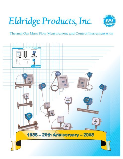
Thermal Gas Mass Flow Measurement and Control Instrumentation
<strong>EPI</strong> produces a wide variety<br />
of thermal instrumentation<br />
for gas mass flow measurement<br />
and control. Built with<br />
over twenty years experience<br />
in thermal mass flow<br />
metering design and production,<br />
our thermal flowmeters<br />
and flow switches are<br />
known for superior quality,<br />
dependability, ease of use,<br />
and durability in real world<br />
applications.<br />
Our Master-Touch Family<br />
of thermal gas mass flowmeters<br />
greatly expanded this<br />
legacy by adding a powerful<br />
microprocessor to our<br />
proven thermal technology<br />
for an unparalleled degree<br />
of flexibility, accuracy, and<br />
control. Upon its introduction,<br />
the Master-Touch raised<br />
the standard for “smart”<br />
technology and it remains at<br />
the forefront of thermal gas<br />
mass flow instrumentation.<br />
Sensor Theory and<br />
Operation<br />
Master-Touch products include a<br />
rugged, cleanable, thermal mass<br />
flow sensor. These units consist of a<br />
sensor assembly which utilizes two<br />
RTD (Resistance Temperature<br />
Detector) sensing elements. The<br />
sensors are constructed of reference<br />
grade platinum, ceramic,<br />
glass, and stainless steel. Two platinum<br />
resistance sensors are built up<br />
upon the ceramic substrate and<br />
then given a thin glass coating.<br />
The assembly is then slipped into a<br />
stainless steel sheath for ruggedness,<br />
corrosion and abrasion resistance.<br />
The sensor assembly is large,<br />
rugged, insensitive to dirt buildup,<br />
and easily cleaned.<br />
During operation, the temperature<br />
sensor constantly measures the<br />
ambient temperature of the gas<br />
and maintains a reference resistance<br />
on one side of a Wheatstone<br />
bridge. The second sensor is<br />
forced through self-heating to a<br />
constant temperature above that<br />
of the gas stream and is controlled<br />
by the temperature sensor and our<br />
forced null Wheatstone bridge<br />
amplifier. Our bridge circuit is set<br />
up with precise resistance values<br />
to maintain the overheat temperature<br />
and to counterbalance the<br />
process gas temperature effects.<br />
Optional wide temperature<br />
ranges are supported by <strong>EPI</strong>’s<br />
patented µp-controlled sensor<br />
bridge.<br />
Since the sensor compensates for<br />
temperature changes and pressure<br />
effects are negligible, the<br />
heated sensor becomes a mass<br />
flow sensor. Gas mass flow across<br />
the heated sensor is measured by<br />
the thermal heat transfer (loss) of<br />
the sensor. Gas molecules absorb<br />
heat while passing the heated<br />
sensor surface. As the velocity of<br />
the gas is increased, more heat is<br />
transferred from the sensor to the<br />
gas stream and more power is<br />
required of the sensor's drive circuit<br />
to maintain a constant sensor<br />
overheat temperature. This heat<br />
transfer is directly proportional to<br />
the mass velocity of the gas (density<br />
x velocity). The power demand<br />
of the flow transmitter is what we<br />
use as our non-linear mass flow or<br />
mass velocity transmitter signal.<br />
This signal is then linearized for a<br />
direct reading of the process flow<br />
output.<br />
Inline & Insertion Styles<br />
The inline style flowmeter assembly<br />
includes the flow sensing element,<br />
temperature sensing element,<br />
bridge amplifier/signal output<br />
board, microprocessor, linearizer<br />
circuit board, transmitter<br />
enclosure, and flow section. The<br />
flow section is specified to match<br />
the user's flow conduit and<br />
plumbed directly in the flow line.<br />
This design has the sensing elements<br />
mounted in the flow section<br />
for exposure to the process gas.<br />
Our inline style flowmeters are<br />
available in sizes from 1/4" pipe<br />
through 4" pipe and are provided<br />
with threaded male NPT ends as<br />
the standard mounting style for<br />
sizes as large as 2 1/2". For sizes 3"<br />
and larger, ANSI 150# flanges are<br />
standard. Optional end mounting<br />
styles may be specified, such as<br />
tube ends, tube end fittings, butt<br />
weld ends, flanged ends, etc. as<br />
required for any size. Pipe sizes in<br />
excess of 4" require insertion style<br />
thermal mass flow meters.<br />
ELDRIDGE PRODUCTS, INC. 2700 Garden Road, Building A Monterey, CA 93940
The insertion style flowmeter<br />
assembly includes the flow sensing<br />
element, temperature<br />
sensing<br />
element,<br />
bridge amplifier/signal<br />
output<br />
board,<br />
mincroprocessor,<br />
linearizer<br />
circuit board,<br />
transmitter<br />
enclosure, and<br />
probe assembly<br />
which supports<br />
the sensing<br />
elements.<br />
This design<br />
requires the<br />
probe assembly to be inserted into<br />
the process gas flow conduit to<br />
allow the process gas to flow<br />
across the sensor assembly. The<br />
insertion style thermal mass flow<br />
meter probe assemblies may be<br />
inserted into any suitable flow section,<br />
pipe, duct, etc.<br />
Our Insertion style thermal mass<br />
flowmeters are available with 1/2",<br />
3/4", or 1" OD probes and may be<br />
installed with pipe fitting connections<br />
or user supplied bored<br />
through tube fittings. Tube fittings,<br />
with or without mounting flange,<br />
are also available from the factory<br />
as an option. The tube length must<br />
be specified upon ordering.<br />
Standard probe lengths are available<br />
in 6” increments for lengths of<br />
6” to 24”, and in 12” for lengths of<br />
24” to 60”.<br />
Integral & Remote<br />
Styles<br />
Integral style flowmeters are<br />
assembled with all electrical components,<br />
digital display and power<br />
supply located within one enclosure.<br />
This enclosure is mounted<br />
directly to the flowbody (inline<br />
thermal mass flowmeters) or probe<br />
assembly (insertion thermal mass<br />
flowmeters).<br />
Remote style flowmeters are<br />
assembled with the flow transmitter<br />
located in an enclosure that is<br />
mounted directly to the flowbody<br />
(inline flowmeters) or probe assembly<br />
(insertion flowmeters). The linearizing<br />
electronics, digital display<br />
and power supply are remotely<br />
mounted for convenient access. A<br />
two-wire, twisted pair cable is typically<br />
used to connect the electronics<br />
enclosures.<br />
Flow Straightening<br />
Asembly<br />
All inline style flowmeters for line<br />
sizes of 3/4” and larger include a<br />
pair of inlet flow conditioners.<br />
These conditioners help to improve<br />
problematic, uneven flow profiles<br />
by disrupting the gas flow and<br />
allowing it to assume a more uniform<br />
profile, without adding any<br />
significant pressure drop in most<br />
applications.<br />
Our Master-Touch<br />
flowmeters<br />
include infrared<br />
communications<br />
via our LightWIRE<br />
technology.<br />
LightWIREenabled<br />
flowmeters are used with<br />
PCs and laptops running<br />
<strong>EPI</strong>Communicator software via<br />
Communicator I RS232 or USB<br />
adapters, or with Communicator II<br />
modules. The Communicator<br />
modules do not include a rating<br />
for hazardous-area locations.<br />
T: 800/321-FLOW(3569) F: 831/648-7780 sales@epiflow.com www.epiflow.com
Our Master-Touch technology<br />
adds a powerful microcontoller<br />
to our proven sensor<br />
and bridge circuitry for<br />
improved performance<br />
and user control. The microcomputer<br />
performs digital<br />
signal processing (DSP) functions<br />
utilizing a high speed,<br />
high resolution 16-bit analog<br />
to digital converter (ADC), a<br />
central processing unit (CPU)<br />
and a high resolution 14-bit<br />
digital to analog converter<br />
(DAC). Operations are performed<br />
in real time while<br />
supporting simultaneous full<br />
duplex RS232 communications.<br />
Digital Subsystems<br />
Five digital subsystems control the<br />
Master-Touch functions:<br />
1. Analog-to-Digital Converter<br />
(ADC) to acquire the data generated<br />
by the sensors.<br />
2. Curve Linearizer to transform<br />
nonlinear to linear voltages.<br />
3. Digital-to-Analog Converter<br />
(DAC) to generate output voltage<br />
from sensor data.<br />
4. Voltage Tracking to perform<br />
real-time processing of input<br />
and output signals.<br />
5. EEPROM to store and maintain<br />
user configurable variables.<br />
Major Features<br />
Every Master-Touch flowmeter supports<br />
up to Four Separate Meter<br />
Ranges that can include independent<br />
calibration data for different<br />
gases, flow ranges, pressures,<br />
etc. The meter ranges can<br />
be selected through the keypad,<br />
a PC, your DCS, or by external<br />
switching.<br />
The Master-Touch provides<br />
Continuous Curve Fitting as the<br />
microprocessor uses a polynomial<br />
curve fit to linearize data into a<br />
continuous linear output with 14-<br />
bit precision. The flowmeter variables<br />
may be viewed without any<br />
interruption to the flow signal or<br />
elapsed flow totalization.<br />
The Master-Touch also supports<br />
Continuous Tracking and<br />
Timestamping of high and low flow<br />
rates. These values can be easily<br />
reset as needed.<br />
The user can choose from a variety<br />
of Engineering Units while the<br />
flowmeter is in operation. All flow<br />
rate, accumulated total, alarm,<br />
and timestamp information is<br />
FLOW<br />
MICROPROCESSOR<br />
OUTPUT<br />
SENSOR<br />
SIGNAL<br />
100%<br />
automatically converted into the<br />
new units.<br />
User input and control of the fieldadjustable,<br />
smart transmitter is supported<br />
by the four-button touch<br />
keypad or via RS232 I/O communications<br />
using <strong>EPI</strong>Communicator<br />
software.<br />
E-Logger includes a fully functional,<br />
PC-based data logger<br />
that works in conjunction with<br />
Master-Touch flowmeters<br />
which have v4.1A and higher<br />
software. The user can select<br />
from a set of categories for the<br />
data collection, the time interval<br />
for each data "snapshot"<br />
and, if necessary, programmed<br />
start and stop times. The data is<br />
stored on either the flowmeter<br />
or a PC. E-Logger will also<br />
graph the data, and it provides<br />
tools for analysis of the data.<br />
Data files stored on a PC can<br />
be accessed by most common<br />
spreadsheet applications.<br />
0%<br />
VOLTS<br />
ELDRIDGE PRODUCTS, INC. 2700 Garden Road, Building A Monterey, CA 93940
<strong>EPI</strong>’s flowmeters have been<br />
installed in a wide variety of<br />
process control applications,<br />
from steel and paper mills to<br />
auto manufacturers to pharmaceutical<br />
houses, from<br />
natural gas submetering and<br />
compressed air consumption<br />
to water & wastewater<br />
treatment plants.<br />
Gas Submetering<br />
For many companies, the use of<br />
natural gas is the obvious choice<br />
for submetering. The gas is typically<br />
delivered through large lines at<br />
very high pressure and the gas<br />
company supplies the figures for<br />
your overall consumption. But<br />
beyond this general custody transfer,<br />
how much do you know about<br />
specific consumption and how are<br />
opportunities for cost savings<br />
determined Submetering at<br />
selected points will show where<br />
the gas is used, how much gas is<br />
used at each location or work<br />
area, and when each location or<br />
work area is using the gas. This is<br />
the information needed to analyze<br />
ongoing expenses and to<br />
refine overall usage.<br />
Compressed Air<br />
Monitoring<br />
In many facilities, compressed air is<br />
one of the primary components of<br />
overall energy use. As energy costs<br />
continue to rise, accurately tracking<br />
the use of compressed air can<br />
produce direct and immediate<br />
benefits by providing the information<br />
you need to establish a program<br />
that:<br />
1) monitors general usage to<br />
encourage cost conservation;<br />
2) tracks peak usage to determine<br />
the optimum compressor<br />
capacity; and<br />
3) simplifies the overall instrumentation<br />
needs through the use of<br />
thermal gas mass flow technology.<br />
<strong>EPI</strong> flowmeters are the instrument<br />
of choice for compressor distributors<br />
and air audit professionals<br />
throughout the country.<br />
Water & Wastewater<br />
Treatment<br />
The treatment of water and wastewater<br />
is a critical element of<br />
municipal responsibility. Increased<br />
public and private awareness of<br />
water quality, availability, and cost<br />
is a driving force behind the<br />
demands for better efficiency and<br />
economy in these processes.<br />
The use of compressed air is necessary<br />
to promote optimal bacteria<br />
growth in aeration basins.<br />
Closely controlling the aeration<br />
process can reduce energy consumption<br />
by as much as 25%, and<br />
accurate measurement is critical<br />
to achieving this goal.<br />
Monitoring Digester or Bio Gas is<br />
equally important. The primary<br />
objective is to achieve an overall<br />
system balance. A secondary<br />
objective is to monitor the excess<br />
gas (waste gas) that is used as a<br />
fuel to power onsite generators<br />
and pumps, or to create energy<br />
for a more widespread power grid.<br />
In addition, monitoring is often a<br />
requirement of local, state, and<br />
Federal environmental guidelines.<br />
Typical Industrial Applications<br />
AUTOMOTIVE INDUSTRY<br />
Compressed air monitoring *<br />
Natural gas consumption * Powder<br />
paint air flow * Paint booth/paint<br />
oven ventilation<br />
UTILITY SERVICES<br />
Stack or flue gas * Waste water<br />
aeration * Ventilation systems *<br />
Digester gas * Gas flows * Nitrogen<br />
purge * Combustion air * Boiler<br />
inlet air<br />
FOOD PROCESSING<br />
Drying air * Ventilation systems *<br />
Boiler inlet air * Exhaust gas *<br />
Process control * Compressor lines<br />
HVAC<br />
Air balancing * Duct flows * Energy<br />
conservation * Fume hoods *<br />
Clean rooms * Laminar flow<br />
benches<br />
LABORATORY AND R & D<br />
Flow research * Biomedical studies<br />
* University studies * Toxicology<br />
studies * Energy studies * Industrial<br />
Hygiene * Occupational Safety *<br />
Experimentation<br />
PETROLEUM & GAS INDUSTRIES<br />
Custody transfer * Landfill gas<br />
recovery * Flare gas measurement<br />
* Gas mixing * Gas quality studies *<br />
Leak testing<br />
RAW MATERIALS INDUSTRIES<br />
Pulp & paper mills * Mining *<br />
Semiconductor manufacturing *<br />
Chemical processing * Primary<br />
metals * Plastics & synthetics<br />
T: 800/321-FLOW(3569) F: 831/648-7780 sales@epiflow.com www.epiflow.com
Manufacturing applications<br />
typically require accurate,<br />
dependable measurement<br />
in an approved industrialstrength<br />
package. Our<br />
Master-Touch MP Series is<br />
the answer to this demand.<br />
Available in a variety of configurations<br />
to meet virtually<br />
any situation, the MP Series is<br />
the instrument of choice<br />
through the world. All of the<br />
MP Series flow transmitters<br />
include an explosion-proof<br />
enclosure for use in hazardous<br />
areas. The remote<br />
signal processor enclosures<br />
are for use in non-hazardous<br />
area locations.<br />
Series 8000MP-8100MP<br />
Master-Touch Series 8000MP-<br />
8100MP flowmeters are inline style<br />
instruments with the flow transmitter<br />
mounted on the flow section<br />
and the signal processor electronics<br />
remotely mounted in a separate<br />
enclosure. Input power is supplied<br />
to the remote electronics.<br />
This configuration uses only a twowire<br />
connection between the flow<br />
transmitter and the signal processor.<br />
Flow sections for pipes ¾" and<br />
larger have flow straightening<br />
screens as standard. Flow sections<br />
for pipes up to 2½" have MNPT<br />
ends as standard; flow sections for<br />
pipes 3" and up have ANSI 150lb.<br />
Class flanges as standard.<br />
Depending on the line size, a variety<br />
of alternatives are available,<br />
including ANSI 300lb. and DIN<br />
flanges, butt ends, sanitary fittings,<br />
etc.<br />
Series 8200MP<br />
Master-Touch Series 8200MP<br />
flowmeters are insertion style instruments<br />
with the flow transmitter<br />
mounted on the sensor probe<br />
assembly and the signal processor<br />
electronics remotely mounted in a<br />
separate enclosure. This configuration<br />
uses only a two-wire connection<br />
between the flow transmitter<br />
and the signal processor. A variety<br />
of installation options are available,<br />
including ball valve retractor<br />
assemblies, tube to pipe compression<br />
fittings, and probe mounted<br />
flanges. Input power is supplied to<br />
the remote electronics.<br />
Series 8600MP-8700MP<br />
Master-Touch Series 8600MP-<br />
8700MP flowmeters are inline style<br />
instruments with all electronics<br />
mounted integrally on the flow<br />
section. All input power and signal<br />
output connections are accessible<br />
through the double-sided enclosure.<br />
Flow sections for pipes ¾" and<br />
larger have flow straightening<br />
screens as standard. Flow sections<br />
for pipes up to 2½" have MNPT<br />
ends as standard; flow sections for<br />
pipes 3" and up have ANSI 150lb.<br />
Class flanges as standard.<br />
Depending on the line size, a variety<br />
of alternatives are available,<br />
including ANSI 300lb. and DIN<br />
flanges, butt ends, sanitary fittings,<br />
etc.<br />
Series 8800MP<br />
Master-Touch Series 8800MP<br />
flowmeters are insertion style instruments<br />
with all electronics mounted<br />
integrally on the sensor probe<br />
assembly. All input power and signal<br />
output connections are accessible<br />
through the<br />
double-sided<br />
enclosure. A variety<br />
of installation<br />
options are available,<br />
including<br />
ball valve retractor<br />
assemblies,<br />
tube to pipe<br />
compression fittings,<br />
and probe<br />
m o u n t e d<br />
flanges.<br />
ELDRIDGE PRODUCTS, INC. 2700 Garden Road, Building A Monterey, CA 93940
ELDRIDGE PRODUCTS, INC.<br />
SHIFT<br />
MODE<br />
MAX<br />
800-321-FLOW<br />
800-321-FLOW<br />
MIN<br />
ELDRIDGE PRODUCTS, INC.<br />
SHIFT<br />
MODE<br />
MAX<br />
MIN<br />
WE WORK AS HARD AS OUR METERS<br />
ELDRIDGE PRODUCTS, INC.<br />
WE WORK AS HARD AS OUR METERS<br />
ELDRIDGE PRODUCTS, INC.<br />
TM<br />
TM<br />
Specifications<br />
* Remote Enclosure<br />
* Remote Enclosure<br />
800-321-FLOW<br />
800-321-FLOW<br />
Linear signal output<br />
Relay Output<br />
Computer Signal Interface<br />
Accuracy, including linearity<br />
(Ref.: 21°C) with ideal flow profile<br />
Repeatability<br />
Sensor flow response time<br />
Turn down ratio<br />
Electronics temperature range<br />
Gas temperature range<br />
Gas pressure effect<br />
Conduit/probe pressure rating range<br />
Input power requirement<br />
Flow Transmitter power requirements<br />
Wetted materials<br />
Standard temperature & pressure<br />
(STP)<br />
NIST traceable calibration<br />
0-5 VDC & 4-20 mA<br />
Two 1-amp, user-selectable alarm<br />
functions<br />
RS232 & RS485<br />
(optional Modbus or HART-compatible)<br />
±[1% of Rdg + (0.5% + .02%/°C<br />
of Full Scale)]<br />
±0.2% of Full Scale<br />
1 second (time constant per step change)<br />
100:1 (15 SCFM/FT 2 minimum Reading)<br />
-40°–85°C (-40°–185°F)<br />
-40°–66°C (-40°–150°F); extended range<br />
available, consult factory<br />
Negligible over ± 20% of absolute<br />
calibration pressure<br />
Vacuum to 500 PSIG standard;<br />
higher pressures, consult factory<br />
24VDC @ 250mA<br />
115 VAC 50/60 Hz optional<br />
230 VAC 50/60 Hz optional<br />
5 watts or less<br />
316 Stainless Steel<br />
(Hastelloy optional)<br />
70°F & 29.92" Hg<br />
(Air .075 lb./cubic foot)<br />
Standard<br />
For use in hazardous area locations:<br />
Class I Division 1 Groups B, C and D; Class II E, F and G; Class III; Type 4X, 7; Ex d IIC; AEx d IIC, IP66; EEx<br />
d IIC, IP66; T2 (consult factory for T3 or T4).<br />
Certified to US requirements; Certified to Canadian requirements<br />
Certified to European ATEX requirements<br />
* Remote Enclosure (Series 8000MP– 8200MP) for use in Ordinary (Non-Hazardous) area locations:<br />
Type 4X, IP66<br />
C<br />
®<br />
US<br />
Series 8000MP-8100MP<br />
Design<br />
Model Pipe OD" x L" SCFM<br />
8036MP-SSS-133 1/4 x 6 3.50<br />
8049MP-SSS-133 3/8 x 6 6.00<br />
8059MP-SSS-133 1/2 x 7 13.0<br />
8069MP-SSS-133 3/4 x 7 60.0<br />
8089MP-SSS-133 1 x 8 90.0<br />
8110MP-SSS-133 1¼ x 10 150<br />
8112MP-SSS-133 1½ x 14 200<br />
8116MP-SSS-133 2 x 14 350<br />
8120MP-SSS-133 2½ x 14 500<br />
8124MP-SSS-133 3 x 14 750<br />
8132MP-SSS-133 4 x 14 1350<br />
Series 8600MP-8700MP<br />
Design<br />
Model Pipe OD" x L" SCFM<br />
8636MP-SSS-133 1/4 x 6 3.50<br />
8649MP-SSS-133 3/8 x 6 6.00<br />
8659MP-SSS-133 1/2 x 7 13.0<br />
8669MP-SSS-133 3/4 x 7 60.0<br />
8689MP-SSS-133 1 x 8 90.0<br />
8710MP-SSS-133 1¼ x 10 150<br />
8712MP-SSS-133 1½ x 14 200<br />
8716MP-SSS-133 2 x 14 350<br />
8720MP-SSS-133 2½ x 14 500<br />
8724MP-SSS-133 3 x 14 750<br />
8732MP-SSS-133 4 x 14 1350<br />
Series 8200MP<br />
Model Probe OD" Max L”<br />
8240MP-SSS-133 1/2 36<br />
8260MP-SSS-133 3/4 60<br />
8280MP-SSS-133 1 84<br />
Series 8800MP<br />
Model Probe OD" Max L”<br />
8840MP-SSS-133 1/2 36<br />
8860MP-SSS-133 3/4 60<br />
8880MP-SSS-133 1 84<br />
Higher flow ranges are available, dependent upon process gas and flow specifications. Please consult<br />
the factory for details.<br />
T: 800/321-FLOW(3569) F: 831/648-7780 sales@epiflow.com www.epiflow.com
In many industries the need<br />
for monitoring gas flow does<br />
not involve hazardous gases<br />
or potentially dangerous<br />
operating conditions. These<br />
applications can include<br />
many water and wastewater<br />
treatment applications, the<br />
HVAC industry, the general<br />
use of compressed air, and<br />
many other applications<br />
using air, nitrogen, argon,<br />
etc. In these cases, an<br />
explosion-proof electronics<br />
enclosure is not required,<br />
and may be considered a<br />
needless expense. To meet<br />
this challenge, Eldridge<br />
Products, Inc. now offers the<br />
Master-Touch Family of<br />
microprocessor-based thermal<br />
gas mass flowmeters in<br />
an economical configuration<br />
intended for use in nonhazardous<br />
area locations.<br />
Series 8000MPNH-<br />
8100MPNH<br />
Master-Touch Series 8000MPNH-<br />
8100MPNH flowmeters are inline<br />
style flowmeters with the flow<br />
transmitter mounted on the flow<br />
section and the signal processor<br />
electronics remotely mounted in a<br />
separate enclosure. Input power is<br />
supplied to the remote electronics.<br />
This configuration uses only a twowire<br />
connection between the flow<br />
transmitter and the signal processor.<br />
Flow sections for pipes ¾" and<br />
larger have flow straightening<br />
screens as standard. Flow sections<br />
have MNPT ends as standard.<br />
Depending on the line size, a variety<br />
of alternatives are available,<br />
including ANSI and DIN flanges,<br />
butt ends, sanitary fittings, etc.<br />
Series 8200MPNH<br />
Master-Touch Series 8200MPNH<br />
flowmeters are insertion style<br />
flowmeters with the flow transmitter<br />
mounted on the sensor probe<br />
assembly and the signal processor<br />
electronics remotely mounted in a<br />
separate enclosure. A variety of<br />
installation options are available,<br />
including ball valve retractor<br />
assemblies, tube to pipe compression<br />
fittings, and probe mounted<br />
flanges. Input power is supplied to<br />
the remote electronics. This configuration<br />
uses only a two-wire connection<br />
between the flow transmitter<br />
and the signal processor.<br />
Series 8600MPNH-<br />
8700MPNH<br />
Master-Touch Series 8600MPNH-<br />
8700MPNH flowmeters are inline<br />
style flowmeters with all electronics<br />
mounted integrally on the flow<br />
section. Flow sections for pipes ¾"<br />
and larger<br />
have flow<br />
straightening<br />
screens<br />
as standard.<br />
Flow<br />
sections<br />
have MNPT<br />
ends as<br />
standard. Depending on the line<br />
size, a variety of alternatives are<br />
available, including ANSI 300lb.<br />
and DN flanges, butt ends, sanitary<br />
fittings, etc.<br />
Series 8800MPNH<br />
Master-Touch Series 8800MPNH<br />
flowmeters are insertion style<br />
flowmeters with all electronics<br />
mounted integrally on the sensor<br />
probe assembly. A variety of installation<br />
options are available,<br />
including ball<br />
valve retractor<br />
assemblies,<br />
tube to pipe<br />
compression<br />
fittings, and<br />
probe mounted<br />
flanges.<br />
ELDRIDGE PRODUCTS, INC. 2700 Garden Road, Building A Monterey, CA 93940
Specifications<br />
Master-Touch<br />
ELDRIDGE PRODUCTS, INC.<br />
800-321-FLOW<br />
Master-Touch<br />
ELDRIDGE PRODUCTS, INC.<br />
800-321-FLOW<br />
MPNH<br />
MPNH<br />
Master-Touch<br />
ELDRIDGE PRODUCTS, INC.<br />
800-321-FLOW<br />
Master-Touch<br />
ELDRIDGE PRODUCTS, INC.<br />
800-321-FLOW<br />
MPNH<br />
MPNH<br />
Linear signal output<br />
Relay Output<br />
Computer Signal Interface<br />
Accuracy, including linearity<br />
(Ref.: 21°C) with ideal flow profile<br />
Repeatability<br />
Sensor flow response time<br />
Turn down ratio<br />
Electronics temperature range<br />
Gas temperature range<br />
Gas pressure effect<br />
Conduit/probe pressure rating range<br />
Input power requirement<br />
Flow Transmitter power requirements<br />
Wetted materials<br />
Standard temperature & pressure<br />
(STP)<br />
NIST traceable calibration<br />
0-5 VDC & 4-20 mA<br />
Two 1-amp, user-selectable alarm<br />
functions<br />
RS232 & RS485<br />
(optional Modbus and HART-compatible)<br />
±[1% of Reading + (0.5% + .02%/°C<br />
of Full Scale)]<br />
±0.2% of Full Scale<br />
1 second (time constant per<br />
step change)<br />
100:1 (15 SCFM/FT 2 minimum Reading)<br />
-40°–85°C (-40°–185°F)<br />
-40°–66°C (-40°–150°F); extended range<br />
available, consult factory<br />
Negligible over ± 20% of absolute<br />
calibration pressure<br />
Vacuum to 500 PSIG standard;<br />
higher pressures, consult factory<br />
24VDC @ 250mA<br />
115 VAC 50/60 Hz optional<br />
230 VAC 50/60 Hz optional<br />
5 watts or less<br />
316 Stainless Steel<br />
(Hastelloy optional)<br />
70°F & 29.92" Hg<br />
(Air .075 lb./cubic foot)<br />
Standard<br />
For use in Ordinary (Non-Hazardous) area locations: Type 4X, IP66<br />
Certified to US requirements; Certified to Canadian requirements<br />
C<br />
®<br />
US<br />
Master-Touch<br />
MPNH<br />
ELDRIDGE PRODUCTS, INC.<br />
800-321-FLOW<br />
Master-Touch<br />
ELDRIDGE PRODUCTS, INC.<br />
800-321-FLOW<br />
MPNH<br />
Series 8000MPNH-8100MPNH Design<br />
Model Pipe OD" x L" SCFM<br />
8036MPNH-SSS-133 1/4 x 6 3.50<br />
8049MPNH-SSS-133 3/8 x 6 6.00<br />
8059MPNH-SSS-133 1/2 x 7 13.0<br />
8069MPNH-SSS-133 3/4 x 7 60.0<br />
8089MPNH-SSS-133 1 x 8 90.0<br />
8110MPNH-SSS-133 1¼ x 10 150<br />
8112MPNH-SSS-133 1½ x 14 200<br />
8116MPNH-SSS-133 2 x 14 350<br />
8120MPNH-SSS-133 2½ x 14 500<br />
8124MPNH-SSS-133 3 x 14 750<br />
8132MPNH-SSS-133 4 x 14 1350<br />
Series 8600MPNH-8700MPNH Design<br />
Model Pipe OD" x L" SCFM<br />
8636MPNH-SSS-133 1/4 x 6 3.50<br />
8649MPNH-SSS-133 3/8 x 6 6.00<br />
8659MPNH-SSS-133 1/2 x 7 13.0<br />
8669MPNH-SSS-133 3/4 x 7 60.0<br />
8689MPNH-SSS-133 1 x 8 90.0<br />
8710MPNH-SSS-133 1¼ x 10 150<br />
8712MPNH-SSS-133 1½ x 14 200<br />
8716MPNH-SSS-133 2 x 14 350<br />
8720MPNH-SSS-133 2½ x 14 500<br />
8724MPNH-SSS-133 3 x 14 750<br />
8732MPNH-SSS-133 4 x 14 1350<br />
Series 8200MPNH<br />
Model Probe OD" Max L”<br />
8240MPNH-SSS-133 1/2 36<br />
8260MPNH-SSS-133 3/4 60<br />
8280MPNH-SSS-133 1 84<br />
Series 8800MPNH<br />
Model Probe OD" Max L”<br />
8840MPNH-SSS-133 1/2 36<br />
8860MPNH-SSS-133 3/4 60<br />
8880MPNH-SSS-133 1 84<br />
Higher flow ranges are available, dependent upon process gas and flow specifications. Please consult<br />
the factory for details.<br />
T: 800/321-FLOW(3569) F: 831/648-7780 sales@epiflow.com www.epiflow.com
ELDRIDGE PRODUCTS, INC.<br />
SHIFT MODE MAX MIN<br />
800-321-FLOW<br />
ELDRIDGE PRODUCTS, INC.<br />
800-321-FLOW<br />
ELDRIDGE PRODUCTS, INC.<br />
<strong>EPI</strong>’s new thermal Flow<br />
Averaging Tubes (FAT)<br />
provide accurate flow<br />
measurement in large pipes<br />
and ducts, offering a costeffective<br />
solution for Heating,<br />
Ventilation, and Air<br />
Conditioning (HVAC) and<br />
Variable Air Volume (VAV)<br />
applications. The Master-<br />
Touch FAT probes utilize a<br />
flow averaging tube to give<br />
a stable flow signal in applications<br />
where the flow profile<br />
is less than ideal, such as<br />
downstream of a bend,<br />
valve, tee or obstruction.<br />
Technology<br />
The flow averaging tube has a<br />
number of large diameter (0.125”)<br />
inlet ports along the length of the<br />
upstream impact surface. The<br />
impact pressure at each inlet port<br />
is averaged inside the tube to create<br />
the axial flow through the tube<br />
and across our thermal flow sensor.<br />
The gas flow then passes back<br />
into the main flow stream through<br />
the gas return ports located near<br />
the flow sensing elements.<br />
Because the velocity impact pressure<br />
follows a square root function,<br />
the average velocity pressure in<br />
Pipe Wall<br />
Master-Touch<br />
IN<br />
FLOW<br />
800-321-FLOW<br />
the FAT probe may vary slightly<br />
from the average of the velocities<br />
at each inlet port. Accuracy shifts<br />
due to anomalies in the actual<br />
flow profile or installations in noncircular<br />
ducts may be corrected<br />
with a local C-Factor adjustment.<br />
Configurations<br />
NOTE:<br />
Requires<br />
mounting<br />
hardware<br />
OUT<br />
FLOW<br />
Pipe Wall<br />
As with our other product lines, the<br />
MP Series Flow Averaging Tubes<br />
have an explosion-proof enclosure<br />
mounted on the probe assembly.<br />
The MPNH Series Flow Averaging<br />
Tubes are intended for use in<br />
Ordinary, or non-hazardous, area<br />
locations and have ABS plastic<br />
enclosures mounted on the probe<br />
assembly. Series 9200MP and<br />
9200MPNH instruments have the<br />
MPNH<br />
9601MP System Control Panel<br />
Patented<br />
flow transmitter enclosure mounted<br />
on the probe assembly, with<br />
the signal processor electronics<br />
remotely mounted in a separate<br />
enclosure. The Series 9800MP and<br />
9800MPNH instruments have<br />
all electronics mounted on the<br />
probe assembly.<br />
The connections for input power<br />
and output signals for the Series<br />
9200MP and 9200MPNH are located<br />
in the remote electronics. This<br />
configuration uses only a two-wire<br />
connection between the flow<br />
transmitter and the signal processor.<br />
All input and output connections<br />
for the Series 9800MP and<br />
9800MPNH are accessed in the<br />
integral electronics enclosure.<br />
The installation of<br />
the tubes in the<br />
pipe or duct typically<br />
uses tube to<br />
pipe compression<br />
fittings or flange<br />
mounts. Multiple<br />
tubes can be<br />
used with a<br />
Model 9601MP<br />
System Control<br />
Panel for an averaged<br />
output.<br />
Master-Touch TM<br />
Series 9600MP<br />
System Control Panel<br />
FLOW<br />
ELDRIDGE PRODUCTS, INC. 2700 Garden Road, Building A Monterey, CA 93940
ELDRIDGE PRODUCTS, INC.<br />
SHIFT MODE MAX MIN<br />
800-321-FLOW<br />
<strong>EPI</strong>’s new thermal Flow<br />
Averaging Tubes (FAT) are<br />
now adapted to inline applications<br />
for installations with<br />
extremely short straight runs<br />
such as retrofits for existing<br />
facilities or as replacements<br />
for other metering devices.<br />
Installation<br />
By itself, <strong>EPI</strong>'s Flow Averaging Tube<br />
technology significantly reduces<br />
the traditional requirements for<br />
straight, unobstructed upstream<br />
piping. Depending upon the piping<br />
configuration, the traditionally<br />
required upstream straight run can<br />
be 10, 20, even 50 diameters. By<br />
measuring the cumulative flow<br />
velocities across one or more<br />
inside diameters, the Flow<br />
Averaging Tubes are far more tolerant<br />
of flow profile problems than<br />
other instrument technologies. This<br />
allows the required straight run to<br />
be greatly reduced from conventional<br />
requirements. In fact, by<br />
incorporating a Flow Straightening<br />
Assembly, the<br />
u p s t r e a m<br />
requirement can<br />
be reduced to<br />
as little as three<br />
diameters.<br />
Series 9100MP-9100MPNH<br />
The Series 9100MP flow averaging<br />
tubes have an explosion-proof<br />
flow transmitter mounted on the<br />
flow section and the signal processor<br />
electronics remotely mounted<br />
in a separate, NEMA 4X enclosure.<br />
The Series 9100MPNH flow averaging<br />
tubes have a NEMA 4X flow<br />
transmitter mounted on the flow<br />
section and the signal processor<br />
electronics remotely mounted in a<br />
separate, NEMA 4X enclosure.<br />
Input power for both series is supplied<br />
to the remote electronics.<br />
This configuration uses only a twowire<br />
connection between the flow<br />
transmitter and the signal processor.<br />
The flow sections have flow<br />
straightening screens as standard.<br />
Flow sections include ANSI 150#<br />
flanges as standard. For other<br />
mounting options, please consult<br />
the factory.<br />
Series 9700MP-9700MPNH<br />
The Series 9700MP flow averaging<br />
tubes have all electronics mounted<br />
on the flow section in an explosion-proof<br />
enclosure. The Series<br />
9700MPNH flow averaging tubes<br />
have all electronics mounted on<br />
the flow section in a NEMA 4X<br />
enclosure. Input power for both<br />
series is supplied to the remote<br />
electronics. This configuration uses<br />
only a two-wire connection<br />
between the flow transmitter and<br />
the signal processor. The flow sections<br />
have flow straightening<br />
screens as standard. Flow sections<br />
include ANSI 150# flanges as standard.<br />
For other mounting options,<br />
please consult the factory.<br />
Flow Plates<br />
Flow Averaging Tube<br />
continued<br />
T: 800/321-FLOW(3569) F: 831/648-7780 sales@epiflow.com www.epiflow.com
* Remote Enclosure<br />
Specifications<br />
Linear signal output<br />
Relay Output<br />
Computer Signal Interface<br />
Accuracy, including linearity<br />
(Ref.: 21°C) with ideal flow profile<br />
Repeatability<br />
Sensor flow response time<br />
Turn down ratio<br />
Electronics temperature range<br />
Gas temperature range<br />
Gas pressure effect<br />
Conduit/peobe pressure rating range<br />
Input power requirement<br />
Flow Transmitter power requirements<br />
Wetted materials<br />
Standard temperature & pressure<br />
(STP)<br />
NIST traceable calibration<br />
0-5 VDC & 4-20 mA<br />
Two 1-amp, user-selectable alarms<br />
RS232 & RS485<br />
(optional Modbus and HART-compatable)<br />
±[1% of Reading + (0.5% + 0.05%/°C<br />
of Full Scale)]<br />
±0.2% of Full Scale<br />
1 second (time constant per step change)<br />
100:1 minimum (but not less than 50 SFPM)<br />
-40°–85°C (-40°–185°F)<br />
-40°–66°C (-40°–150°F)<br />
Negligible over ± 10% of absolute<br />
calibration pressure<br />
Vacuum to 150 PSIG standard;<br />
higher pressures, consult factory<br />
24VDC @ 250mA<br />
115 VAC 50/60 Hz optional<br />
230 VAC 50/60 Hz optional<br />
5 watts or less<br />
316 Stainless Steel<br />
70°F & 29.92" Hg<br />
(Air .075 lb./cubic foot)<br />
Standard<br />
MP Series:<br />
Class I Division 1 Groups B, C and D; Class II E, F and G; Class III; Type 4X, 7; Ex d IIC; AEx d IIC, IP66; EEx<br />
d IIC, IP66; T2 (consult factory for T3 or T4).<br />
Certified to US requirements; Certified to Canadian requirements<br />
C<br />
®<br />
US<br />
Patented<br />
Certified to European ATEX requirements<br />
* Remote Enclosure (Series 8000MP– 8200MP) and MPNH Series for use in Ordinary (Non-Hazardous)<br />
area locations: Type 4X, IP66<br />
U. S. Patent No. 6,883,389 Other U.S. & foreign patents pending.<br />
Series 9100MP<br />
Design<br />
Model Pipe OD" x L" SCFM<br />
9116MP-SSS-133 2 x 14 1400<br />
9120MP-SSS-133 2½ x 14 2000<br />
9124MP-SSS-133 3 x 14 3000<br />
9132MP-SSS-133 4 x 14 5400<br />
9148MP-SSS-133 6 x 14 12000<br />
Series 9200MP<br />
Model Probe OD" Max L”<br />
9240MP-SSS-133 1/2 36<br />
9260MP-SSS-133 3/4 60<br />
9280MP-SSS-133 1 84<br />
Series 9700MP<br />
Design<br />
Model Pipe OD" x L" SCFM<br />
9716MP-SSS-133 2 x 14 1400<br />
9720MP-SSS-133 2½ x 14 2000<br />
9724MP-SSS-133 3 x 14 3000<br />
9732MP-SSS-133 4 x 14 5400<br />
9748MP-SSS-133 6 x 14 12000<br />
Series 9800MP<br />
Model Probe OD" Max L"<br />
9840MP-SSS-133 1/2 36<br />
9860MP-SSS-133 3/4 60<br />
9880MP-SSS-133 1 84<br />
Series 9100MPNH<br />
Design<br />
Model Pipe OD" x L" SCFM<br />
9116MPNH-SSS-133 2 x 14 1400<br />
9120MPNH-SSS-133 2½ x 14 2000<br />
9124MPNH-SSS-133 3 x 14 3000<br />
9132MPNH-SSS-133 4 x 14 5400<br />
9148MPNH-SSS-133 6 x 14 12000<br />
Series 9200MPNH<br />
Model Probe OD" Max L”<br />
9240MPNH-SSS-133 1/2 36<br />
9260MPNH-SSS-133 3/4 60<br />
9280MPNH-SSS-133 1 84<br />
Series 9700MPNH<br />
Design<br />
Model Pipe OD" x L" SCFM<br />
9116MPNH-SSS-133 2 x 14 1400<br />
9120MPNH-SSS-133 2½ x 14 2000<br />
9724MPNH-SSS-133 3 x 14 3000<br />
9732MPNH-SSS-133 4 x 14 5400<br />
9748MPNH-SSS-133 6 x 14 12000<br />
Series 9800MPNH<br />
Model Probe OD" Max L"<br />
9840MPNH-SSS-133 1/2 36<br />
9860MPNH-SSS-133 3/4 60<br />
9880MPNH-SSS-133 1 84<br />
ELDRIDGE PRODUCTS, INC. 2700 Garden Road, Building A Monterey, CA 93940
The Series 9000MP Multipoint<br />
Systems are designed to<br />
measure air and gas flow in<br />
systems where two or more<br />
sensing points are required<br />
due to large cross-sectional<br />
areas. The typical Series<br />
9000MP Multipoint System<br />
includes one or more Series<br />
9000MP Probe and a Series<br />
9600MP System Control<br />
Panel. The new APS air<br />
purge system and support<br />
for multiple C-Factors<br />
make the Series 9000MP<br />
your complete solution.<br />
Technology<br />
The 9000MP flow transmitter probe<br />
assembly is the heart of the system.<br />
The probe assembly consists of two<br />
or more flow sensors (maximum of<br />
5 sensors per probe) mounted in a<br />
1½" OD probe shaft. Each sensor is<br />
matched to its own bridge board<br />
and is individually calibrated and<br />
linearized. The bridge board and<br />
microprocessor for each sensor<br />
are mounted outside of the flow<br />
duct in an enclosure at the end of<br />
the probe shaft.<br />
The voltage output from each sensor<br />
and bridge board set is sent to<br />
its own microprocessor board for<br />
accurate linearization of the flow<br />
rate signal. The linearized output<br />
signals from the multiple sensors in<br />
the probe are then averaged by<br />
the summer/averager module.<br />
Typically, the probe assembly's<br />
averaged output signal is transmitted<br />
to the remote system control<br />
panel for grand averaging with<br />
the signals from other probe<br />
assemblies. However, flow transmitter<br />
assemblies may be specified<br />
with either one average output<br />
signal and/or individual signals<br />
to allow individual sensor readings<br />
at the system control panel.<br />
The Series 9601MP system control<br />
panel is housed in a 12" x 10" NEMA<br />
4X fiberglass enclosure. This enclosure<br />
holds the power supply, the<br />
summer/averager board (required<br />
for systems with multiple probe<br />
assemblies), and a microprocessor<br />
board for control of the overall system<br />
output signal, and can be<br />
located from as little as a few feet<br />
to as much as thousands of feet<br />
from the transmitter probe assemblies.<br />
The control panel provides the<br />
power for the probe assemblies.<br />
The flow transmitter sends its signal<br />
to the control panel over a 4-20<br />
mA signal loop. This method<br />
requires a four wire connection<br />
per probe assembly (power supply<br />
positive, power ground, 4-20 mA<br />
average output and return). The<br />
control panel provides two analog<br />
output signals (0-5 VDC and 4-20<br />
mA) linearized proportionally to<br />
the grand average flow rate, as<br />
well as RS232/485 digital interfaces<br />
for communication with a PC running<br />
<strong>EPI</strong>Communicator software.<br />
The 4-20 mA grand average output<br />
can drive up to 1200 ohms.<br />
Modbus and HART-compatible<br />
options are available<br />
Air Purge System<br />
The <strong>EPI</strong> Air Purge System (APS) provides<br />
a means of cleaning the sensors<br />
in applications where dry particulates<br />
may build up on the sensors<br />
and cause problems. A stainless<br />
steel tube is mounted on the<br />
downstream side of the probe support<br />
with a pair of outlet holes positioned<br />
at each sensor. The tube is<br />
connected to a tap located on<br />
the mounting flange. After basic<br />
installation of the multipoint system<br />
is complete, a pressurized gas line<br />
(typically compressed air) is connected<br />
to the tap. The pressurized<br />
gas is released at set intervals by<br />
the user to clean the sensor surface<br />
of any accumulated particulates.<br />
The frequency and duration<br />
of the the purging gas stream can<br />
be controlled by the Master-Touch<br />
software or externally by the customer.<br />
The purge gas must be compatible<br />
with the process gas. Pre-heating<br />
the purge gas to the temperature<br />
of the process gas is recommended.<br />
By pre-heating the<br />
purge gas, one may avoid adhesion<br />
of certain particulate matter<br />
to sensor and probe surfaces.<br />
Consult the <strong>EPI</strong> factory for preheating<br />
solutions.<br />
continued<br />
T: 800/321-FLOW(3569) F: 831/648-7780 sales@epiflow.com www.epiflow.com
ELDRIDGE PRODUCTS, INC.<br />
SHIFT MODE MAX MIN<br />
800-321-FLOW<br />
ELDRIDGE PRODUCTS, INC.<br />
800-321-FLOW<br />
Specifying a Series 9000MP<br />
Multipoint System<br />
The chart to the right is a guideline<br />
for how many traverse points are<br />
suggested for a circular duct.<br />
Once the average flow rate is<br />
determined, the factory can<br />
specify the minimum number of<br />
sensors in a Series 9000MP<br />
Multipoint System. If the point of<br />
average flow cannot be determined,<br />
then a simple rule is to<br />
specify the number of points<br />
based on the chart.<br />
The greater the number of points<br />
measured, the greater the accuracy<br />
of the final average flow rate.<br />
Also note that the accuracy of<br />
any one point becomes of less<br />
importance to the final accuracy<br />
of the total flow rate as the number<br />
of points is increased because<br />
of the averaging method utilized.<br />
Duct Suggested Number Suggested Sensors Total Number<br />
Diameter of Probes per Probe of Sensors<br />
8" – 18" 1 2 2<br />
18" – 24" 1 4 4<br />
24" – 36" 2 2 4<br />
36" – 60" 2 4 8<br />
Larger Ducts and Stacks – Consult factory for configuration options.<br />
Rectangular Ducts – Allow one to two square feet per point. Fewer traverse<br />
points may be used if a careful study shows that uniformity of flow<br />
exists.<br />
Master-Touch TM<br />
Series 9600MP<br />
System Control Panel<br />
FLOW<br />
ELDRIDGE PRODUCTS, INC. 2700 Garden Road, Building A Monterey, CA 93940
ELDRIDGE PRODUCTS, INC.<br />
SHIFT MODE MAX MIN<br />
800-321-FLOW<br />
Series 9600MP<br />
System Control Panel<br />
ELDRIDGE PRODUCTS, INC.<br />
800-321-FLOW<br />
Series 9600MP<br />
System Control Panel<br />
Master-Touch TM<br />
Series 9000MP<br />
Multipoint Probe<br />
with mounting hardware<br />
DESF — 1½” ANSI 150#<br />
Mating Flange<br />
Specifications<br />
Linear signal output<br />
Relay Output<br />
Computer Signal Interface<br />
Accuracy, including linearity<br />
(Ref.: 21°C)<br />
Repeatability<br />
Sensor flow response time<br />
Turn down ratio<br />
Electronics temperature range<br />
Gas temperature range<br />
(All calibrations performed in<br />
Ambient Temp. & Pressure Air)<br />
Gas pressure effect<br />
Probe pressure rating range<br />
Input power requirement<br />
0-5 VDC & 4-20 mA<br />
Two 1-amp, user-selectable alarm<br />
functions<br />
RS232 & RS485<br />
(optional Modbus and HART-compatible)<br />
±[1.0% of Reading + (0.5% + 0.02%/°C<br />
of Full Scale)]<br />
±0.2% of Full Scale<br />
1 second (time constant per<br />
step change)<br />
100:1 minimum<br />
(but not less than 15 SFPM)<br />
-40°–85°C (-40°–185°F);<br />
extended temperature optional<br />
-40°–66°C (-40°–150°F); extended range<br />
available, consult factory<br />
Negligible over ± 10% of absolute<br />
calibration pressure<br />
Vacuum to 50 PSIG;<br />
higher pressures, consult factory<br />
24VDC @ 250mA per sensor<br />
115 VAC 50/60 Hz optional<br />
230 VAC 50/60 Hz optional<br />
5 watts or less per sensor<br />
Series 9000/9600MP power<br />
requirements<br />
Series 9600MP enclosure NEMA 4X fiberglass, 10” x 12” x 6”<br />
Series 9000MP probe enclosure NEMA 4X fiberglass, 8” x 10” x 4”<br />
Wetted materials<br />
316 Stainless Steel<br />
Standard temperature & pressure 70°F & 29.92" Hg<br />
(STP)<br />
(Air .075 lb./cubic foot)<br />
NIST traceable calibration<br />
Standard<br />
DESC — 1½” Tube<br />
End Cap<br />
Series 9000MP<br />
Model*<br />
9001MP-06-01-XX”-DESFC<br />
9002MP-06-01-XX”-DESFC<br />
9003MP-06-01-XX”-DESFC<br />
9004MP-06-01-XX”-DESFC<br />
9005MP-06-01-XX”-DESFC<br />
Description<br />
Probe assembly with 1 sensor and hardware<br />
Probe assembly with 2 sensors and hardware<br />
Probe assembly with 3 sensors and hardware<br />
Probe assembly with 4 sensors and hardware<br />
Probe assembly with 5 sensors and hardware<br />
* (XX” equals probe length)<br />
-APS Air Purge System option (added to part number)<br />
DESFC — All mounting hardware<br />
NOTE — DESF & DESC must be welded<br />
to user’s duct or pipe<br />
Series 9601MP<br />
Model<br />
9601MP-133-1210-DC24<br />
9601MP-133-1210-AC115<br />
9601MP-133-1210-AC230<br />
Description<br />
System Control Panel with 24 VDC input power<br />
System Control Panel with 115 VAC input power<br />
System Control Panel with 230 VAC input power<br />
T: 800/321-FLOW(3569) F: 831/648-7780 sales@epiflow.com www.epiflow.com
Ball Valve Retractor<br />
Assembly<br />
Optional ball valve<br />
assemblies are<br />
available through<br />
<strong>EPI</strong> which allow the<br />
removal of the<br />
insertion style flow<br />
transmitter assemblies<br />
for service,<br />
calibration, cleaning,<br />
etc. The valve<br />
provides a means<br />
to seal off leaks of<br />
the process gas at<br />
the point of insertion<br />
after the probe<br />
assembly has been<br />
removed.<br />
BVR0812 — ½" bore<br />
x ¾" NPT x 10" long<br />
BVR1216 — ¾" bore<br />
x 1" NPT x 11" long<br />
BVR1620 — 1" bore<br />
x 1¼" NPT x 12" long<br />
Tube-to-Pipe Adapter<br />
Bored thru tube-to-pipe<br />
adapter fittings are also<br />
available from the factory.<br />
TPM0808T — ½" tube x ½"<br />
male pipe bored thru fitting<br />
with Teflon ferrule<br />
TPM1212T — ¾" tube x ¾" male<br />
pipe bored thru fitting with Teflon<br />
ferrule<br />
TPM1216T — ¾" tube x 1" male<br />
pipe bored thru fitting with Teflon<br />
ferrule<br />
TPM1616T — 1" tube x 1" male pipe<br />
bored thru fitting with Teflon ferrule<br />
TPMXXXXS — Same as above<br />
except stainless steel ferrule<br />
Eldridge Products, Inc. Terms and Conditions<br />
Specification Notice<br />
Specifications contained herein are subject to change without notice. <strong>EPI</strong> cannot guarantee<br />
the applicability or suitability of our products in all situations, since it is impossible to<br />
anticipate or control every condition under which our products and specifications may be<br />
used.<br />
Limited Acceptance<br />
Acceptance of an <strong>EPI</strong> offer is limited to its terms. Acceptances or confirmations that state<br />
additional or differing terms from the price quote shall be operative as acceptances, but<br />
all additional or differing terms shall be deemed material alterations within the meaning of<br />
Commercial Code Section 2207(2)(b), and notice of objection to them pursuant to<br />
Commercial Code Section 2207(2)(c) is hereby given. The laws of the State of California<br />
govern the contract and venue is Monterey County. Risk of loss passes F.O.B. <strong>EPI</strong> factory.<br />
Payment due in full in US Dollars within credit terms granted from factory shipment.<br />
Additional fees shall include interest on unpaid balances that are outstanding for more than<br />
granted credit terms, plus all collection costs and attorneys' fees incurred in collecting any<br />
outstanding balance. Any and all additional or differing terms do not become part of the<br />
contract between <strong>EPI</strong> and any purchaser.<br />
The terms of the offer are expressly limited to the terms detailed in any product brochure or<br />
price quote. Any modification to any of the terms of the offer must be in writing and must<br />
be signed by an officer of <strong>EPI</strong>.<br />
Limited Warranty<br />
Eldridge Products, Inc. (<strong>EPI</strong>) warrants its products to be free from defects in materials and<br />
workmanship for one year from the date of factory shipment. If there is a defect, the purchaser<br />
must notify <strong>EPI</strong> of the defect within the warranty period. Upon receipt of the defective<br />
product, <strong>EPI</strong> will either repair the defective product, or provide an <strong>EPI</strong> replacement, or<br />
refund the purchase price of the defective product, at its sole option. <strong>EPI</strong> MAKES NO OTHER<br />
WARRANTY, EXPRESS OR IMPLIED, AS TO THE PRODUCTS. <strong>EPI</strong> MAKES NO WARRANTY THAT THE<br />
GOODS SOLD TO ANY PURCHASER ARE FIT FOR ANY PARTICULAR PURPOSE. FURTHERMORE,<br />
<strong>EPI</strong> MAKES NO WARRANTY OF MERCHANTABILITY WITH RESPECT TO ANY PRODUCTS SOLD TO<br />
ANY PURCHASERS. There are no other warranties that extend beyond the description on any<br />
brochure or price quote.<br />
2700 Garden Road, Building A<br />
Monterey, CA 93940<br />
Tel: 800/321-FLOW(3569)<br />
Fax: 831/648-7780<br />
sales@epiflow.com<br />
www.epiflow.com<br />
®<br />
C<br />
US<br />
80400101 rev. 3


![[PSS 1-8A3 A] Model 84F Flanged Body Flowmeters; Model 84W ...](https://img.yumpu.com/33332673/1/190x245/pss-1-8a3-a-model-84f-flanged-body-flowmeters-model-84w-.jpg?quality=85)