SRI986 Electro-Pneumatic Positioner
SRI986 Electro-Pneumatic Positioner
SRI986 Electro-Pneumatic Positioner
- No tags were found...

Create successful ePaper yourself
Turn your PDF publications into a flip-book with our unique Google optimized e-Paper software.
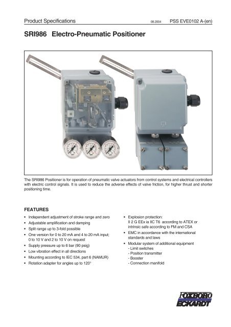
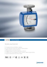
Product Specifications 08.2004 PSS EVE0102 A-(en)<strong>SRI986</strong> <strong>Electro</strong>-<strong>Pneumatic</strong> <strong>Positioner</strong>The <strong>SRI986</strong> <strong>Positioner</strong> is for operation of pneumatic valve actuators from control systems and electrical controllerswith electric control signals. It is used to reduce the adverse effects of valve friction, for higher thrust and shorterpositioning time.FEATURES• Independent adjustment of stroke range and zero• Adjustable amplification and damping• Split range up to 3-fold possible• One version for 0 to 20 mA and 4 to 20 mA input;0 to 10 V and 2 to 10 V on request• Supply pressure up to 6 bar (90 psig)• Low vibration effect in all directions• Mounting according to IEC 534, part 6 (NAMUR)• Rotation adapter for angles up to 120°• Explosion protection:II 2 G EEx ia IIC T6 according to ATEX orintrinsic safe according to FM and CSA• EMC in accordance with the internationalstandards and laws• Modular system of additional equipment- Limit switches- Position transmitter- Booster- Connection manifold
2 <strong>SRI986</strong> PSS EVE0102 A-(en)TECHNICAL DATAInputSignal range ............0...20mA/4...20mA or0 ... 10 V / 2 ... 10 VInput resistance ..........
PSS EVE0102 A-(en) <strong>SRI986</strong> 3MaterialsHousing ................Aluminum (Alloy No. 230)finished with DD-varnishgrey blueAll moving parts offeedback system .........WNr.1.4305 / 1.4571Mounting bracket .........Aluminum (Alloy No. 230)Weightsingle acting. ............approx. 1.5 kg (3.3 lbs)double acting ............approx. 1.8 kg (3.9 lbs)Attachment kitfor diaphragm actuators. . . approx. 0.3 kg (0.6 lbs)forrotaryactuators ......approx. 0.5 kg (1.1 lbs)Connection<strong>Pneumatic</strong>..............FemalethreadsG 1/8 acc. to ISO 228ElectricLine entry .............1or2cableglandsM20x1.5or1/2-14NPT(others with Adapter AD-...)Cable diameter. ........6-12mm(0.24-0.47in)Screw terminals ........Screw terminals for wiresup to 2.5 mm 2 (AWG 14)MountingType of mounting .........forattaching to diaphragmactuators acc. to IEC 534-6(NAMUR) and to rotaryactuatorsMounting orientation. ......any
4 <strong>SRI986</strong> PSS EVE0102 A-(en)ADDITIONAL EQUIPMENTAdditional equipment is installed by the manufacturer, butsome types can also be put in later on. Therefore specialpart sets are available.Inductive Limit Switch, two-wire systemCode P, Q, T, UInput ..................Stroke/angle from actuatorvia positioner feedback leverOutput.................2inductive proximity sensorsacc. to DIN 19 234 resp.NAMUR for connection toa switching amplifier withan intrinsically safe control1) 2) 3)circuitCurrent consumptionVane clear. ............>3mAVaneinterposed........
PSS EVE0102 A-(en) <strong>SRI986</strong> 5Electrical Position TransmitterCode FSensor.................resistiveprecisionconductive plastic elementInput ..................Stroke/angle from actuatorvia positioner feedback leverStroke range ...........8...100mm(0.3...4in)Angular range ..........60...120°Output.................two-wiresystemSignal range ...........4...20mAUPermitted load. .........R = −12VSBmax002 . A(U S = Supply voltage)Power supplySupply voltage .........DC12...36VPermitted ripple. ........
6 <strong>SRI986</strong> PSS EVE0102 A-(en)SAFETY REQUIREMENTSSafetyacc. to EN 61 010-1(resp. IEC 1010-1) ........safetyclassIII,pollution degree 2,overvoltage category ILimit Switch Code V(additional equipment) .....safetyclassII,pollution degree 2,overvoltage category IIExplosion protection type EEx ia/ib 1)Basic device Type .......AI633Typeofprotection.......II2GEExib/iaIIB/IIC T4/T6Certificateofconformity...PTB02ATEX2153For operation in certified intrinsically safe circuits with thefollowing maximum values of input circuit:U i ...................30VI i.....................150mAP i....................refertofollowing table:P i [W] T6 [°C] T6 [°C]2 40 901.5 50 901 57.5 90Internal inductance ......negligibleInternal capacitance .....negligibleThe control circuit is galvanically separate from earth and allother electric circuits.Limit Switch Code T, U (additional equipment)Type of protection Intrinsic safety EEx ib/ia IIB/IICwith the following maximum values:U i ...................16VI i.....................25mAP i....................64mWInternalinductance......100µHInternal capacitance .....30nFThe signal circuits are galvanically separate from earth,from each other and from all other electric circuits.Position Transmitter Code F (additional equipment)Type of protection Intrinsic safety EEx ib/ia IIB/IICwith the following maximum values:for temperature class T4 and a maximally permissibleoutside ambient temperature of 80 °C:U i ...................30VI i.....................130mAP i....................0.9Wfor temperature class T4 and a maximally permissibleoutside ambient temperature of 60 °C:U i ...................22VI i.....................66mAP i....................0.5WThe effective internal inductance L i left amounts to 9 µH,the effective capacity C i against earth amounts to 10 nFand/or differential 6 nF.The supply- and signal circuits are galvanically separatefrom earth and from all other electric circuits.1) National installation regulations must be observedThe national regulations must be strictly observed when retrofitting theelectrical position transmitter type AI 633 in the electro-pneumaticpositioner of type AI 633 or the inductive limit switch type AI 633 K in theelectro-pneumatic positioner of type AI 633 (<strong>SRI986</strong>-BIDS2EBB and<strong>SRI986</strong>-CIDS2EBB).The following regulations apply to the Federal Republic of Germany:The installation must be carried out by the manufacturer, or the productmust be tested by a qualified inspector as a special version inaccordance with ElexV.
PSS EVE0102 A-(en) <strong>SRI986</strong> 7Explosion protection Zone 2 1)It is recommended that the instrument version for protectiontype EEx ia is used.In the Federal Republic of Germany these instruments maybe operated in Zone 2 with non-intrinsically safe circuits ifthe operating values do not exceed the maximum referencevalues.Explosion protection according to FM and CSA 1)<strong>Electro</strong>-pneumatic positioner type BIM 633Intrinsically safe, Class I, Division 1,Groups A, B, C, D, hazardous locations1) National installation regulations must be observed
8 <strong>SRI986</strong> PSS EVE0102 A-(en)MODEL CODES <strong>SRI986</strong><strong>Electro</strong>-<strong>Pneumatic</strong> <strong>Positioner</strong><strong>SRI986</strong>VersionSingle Acting . . . . . . . . . . . . . . . . . . . . . . . . . -BDouble Acting. . . . . . . . . . . . . . . . . . . . . . . . . -CInputSignal Range 4 - 20 mA . . . . . . . . . . . . . . . . . . . . . . . -IMode of ActionStandard Version Increasing Input Increases Output . . . . . . . . . . . . . DUniversal Version Set To Increasing Input Decreases Output . . . . . . . . RBuilt-In Limit Switch/Position TransmitterWithout . . . . . . . . . . . . . . . . . . . . . . . . . . . . . . . . . . . . . . . SInductive Limit Switch Three-Wire Technique, Without Explosion Protection . (a) . . RInductive Limit Switch (Standard Version) . . . . . . . (a). . . . . . . . . . . . . TInductive Limit Switch (Security Version) . . . . . . . . (a). . . . . . . . . . . . . UTwo Micro Switches, Without Explosion Protection. . . (a) . . . . . . . . . . . . . VPositionTransmitter4-20mA . . . . . . . . . . . . . (a). . . . . . . . . . . . . FCable Entry1/2"-14 NPT (with Adapter(s) M20x1,5 to 1/2"-14 NPT) . . . . . . . . . . . . . . . . . . . 6M20 x 1.5 With One Plastic Cable Gland, Color Gray. . . . . . . . . . . . . . . . . . . . 7Electrical Certification: (Only Standard Device)II 2 G EEx ia IIC T6 according to ATEX . . . . . . . . (d) . . . . . . . . . . . . . . . . . . . EAAFM Approved For Intrinsic Safety Cl. I, Div. 1, Groups A,B,C,D Hazardous Locations Indoors . . FAACSA Approved For Intrinsic Safety Cl. I, Div. 1, Groups A,B,C,D Hazardous Locations Indoors. . CAAWithout . . . . . . . . . . . . . . . . . . . . . . . . . . . . . . . . . . . . . . . . . . . . . ZZZAttachment KitOrder as Auxiliary . . . . . . . . . . . . . . . . . . . . . . . . . . . . . . . . . . . . . . . . . . . . NManifoldOrder as Auxiliary . . . . . . . . . . . . . . . . . . . . . . . . . . . . . . . . . . . . . . . . . . . . . . . . AOptionsAmplifier Free Of Nonferrous Metals . . . . . . . . . (a)(b). . . . . . . . . . . . . . . . . . . . . . . . . . . . . . -CProtection Class IP65 . . . . . . . . . . . . . . . . . . . . . . . . . . . . . . . . . . . . . . . . . . . . . . . . . -FSignal Range 0 - 20 mA instead of 4 - 20 mA . . . . . . . . . . . . . . . . . . . . . . . . . . . . . . . . . . . . . . -IDesigned For Auxiliary Energy Oxygen Max 6 Bar (With BAM Certificate) . . . . . . . . . . . . . . . . . . . . . . . -STag No. LabelingStamped With Weather Resistant Color . . . . . . . . . . . . . . . . . . . . . . . . . . . . . . . . . . . . . . . . -GStainless Steel Label Fixed With Wire . . . . . . . . . . . . . . . . . . . . . . . . . . . . . . . . . . . . . . . . . -LExample: <strong>SRI986</strong> -B I D S 7 ZZZ N A -CGFootnotesa) Not available with FAA & CAAb) Only available with Version -Bd) Not available with Limit Switch Codes R, VPartsAuxiliarys see EVE9902Fittings see EOO9001
PSS EVE0102 A-(en) <strong>SRI986</strong> 9MODEL CODESAccessoriesAttachment kitEBZGfor diaphragm actuators with casting yoke acc. to NAMUR (incl. standard Couple lever) (for <strong>SRI986</strong>) . . . . . . . . . -HNfor diaphragm actuators with pillar yoke acc. to NAMUR (incl. standard Couple lever) (for <strong>SRI986</strong>) . . . . . . . . . . . -KNfor rotary actuators, without flange, 3 drill holes 6,5 mm (for SRP981, SRI983, <strong>SRI986</strong>, SMP981, SMI983, SGE985). . -PNfor rotary actuators, without flange, 4 threads M6 (for SRP981, SRI983, <strong>SRI986</strong>, SMP981, SMI983, SGE985) . . . . . -NNfor rotary actuators, with flange (for SRP981, SRI983, <strong>SRI986</strong>, SMP981, SMI983, SGE985) . . . . . . . . . . . . . . -JNfor rotary actuators, with shaft (for SRP981, SRI983, <strong>SRI986</strong>, SMP981, SMI983, SGE985) . . . . . . . . . . . . . . -ZNfor Masoneilan type Camflex II (for SRP981, SRI983, <strong>SRI986</strong>, SMP981, SMI983, SGE985) . . . . . . . . . . . . . . -RNCouple lever / camstandard (a = 72 mm) . . . . . . . . . . . . . . . . . . . . . . . . . . . . . . . . . . . . . . . . . . . . . . . . . -ANextended (a = 91 mm) . . . . . . . . . . . . . . . . . . . . . . . . . . . . . . . . . . . . . . . . . . . . . . . . . -BNinverse equal percentage cam for rotary actuators . . . . . . . . . . . . . . . . . . . . . . . . . . . . . . . . . . . -CNSpring setFESGrange-springs (4pc.) . . . . . . . . . . . . . . . . . . . . . . . . . . . . . . . . . . . . . . . . . . . . . . . . . . -FNManifold (Connection 1/4-18NPT)LEXGstaggered connections (for SRP981, <strong>SRI986</strong>) . . . . . . . . . . . . . . . . . . . . . . . . . . . . . . . . . . . . . -BNconnections same level (for SRP981, <strong>SRI986</strong>). . . . . . . . . . . . . . . . . . . . . . . . . . . . . . . . . . . . . -CNwith gauges for supply air, y, for version single acting (for SRP981,<strong>SRI986</strong>) . . . . . . . . . . . . . . . . . . . . . . -JNwith gauges for supply air, y1, y2, for version double acting (for SRP981, <strong>SRI986</strong>) . . . . . . . . . . . . . . . . . . . -MNgauge manifold without gauge, for version single acting (for SRP981, <strong>SRI986</strong>). . . . . . . . . . . . . . . . . . . . . -RNgauge manifold without gauge, for supply air, y1, y2, for version double acting (for SRP981, <strong>SRI986</strong>) . . . . . . . . . -SNBooster (Connection 1/4-18NPT)VKXGfor Version single acting (for SRP981, <strong>SRI986</strong>) . . . . . . . . . . . . . . . . . . . . . . . . . . . . . . . . . . . . -FNfor Version double acting (for SRP981, <strong>SRI986</strong>) . . . . . . . . . . . . . . . . . . . . . . . . . . . . . . . . . . . . -GNfor Version single acting with doubled output capacity (for SRP981, <strong>SRI986</strong>). . . . . . . . . . . . . . . . . . . . . . -HNAdapter (Material SS)ADAdapter 1/2" NPT to 3/4" NPT . . . . . . . . . . . . . . . . . . . . . . . . . . . . . . . . . . . . . . . . . . . . . -A3Adapter (stainless steel) M20x1.5 to 1/2"-14NPT (internal thread) . . . . . . . . . . . . . . . . . . . . . . . . . . . -A6Adapter (stainless steel) M20x1.5 to PG 13.5 (internal thread) . . . . . . . . . . . . . . . . . . . . . . . . . . . . . -A7Adapter (stainless steel) M20x1.5 to G 1/2" (internal thread) . . . . . . . . . . . . . . . . . . . . . . . . . . . . . . -A8Adapter (plastic) M20x1.5 to PG 13.5 (internal thread) . . . . . . . . . . . . . . . . . . . . . . . . . . . . . . . . . -A9Cable glandBUSGPG 13.5 Plug-connector for Fieldbus (ss/ threaded connection 7/8 - UN) . . . . . . . . . . . . . . . . . . . . . . . . -F1M20x1.5 Plug-connector for Fieldbus (ss/ threaded connection 7/8 - UN). . . . . . . . . . . . . . . . . . . . . . . . -F2PG 13.5 plastics, color gray . . . . . . . . . . . . . . . . . . . . . . . . . . . . . . . . . . . . . . . . . . . . . . -K1PG 13.5 plastics, color blue . . . . . . . . . . . . . . . . . . . . . . . . . . . . . . . . . . . . . . . . . . . . . . -K2PG 13.5 plastics, color white . . . . . . . . . . . . . . . . . . . . . . . . . . . . . . . . . . . . . . . . . . . . . -K4M20x1.5 plastics, color gray . . . . . . . . . . . . . . . . . . . . . . . . . . . . . . . . . . . . . . . . . . . . . . -K6M20x1.5 plastics, color blue . . . . . . . . . . . . . . . . . . . . . . . . . . . . . . . . . . . . . . . . . . . . . . -K7M20x1.5 plastics, color black. . . . . . . . . . . . . . . . . . . . . . . . . . . . . . . . . . . . . . . . . . . . . . -K8M20x1.5 plastics, color white . . . . . . . . . . . . . . . . . . . . . . . . . . . . . . . . . . . . . . . . . . . . . -K9PG 13.5 Plug-connector for Fieldbus (ss/ threaded connection M12) . . . . . . . . . . . . . . . . . . . . . . . . . . -P1PG 13.5 HF-cable gland for Fieldbus (ss) . . . . . . . . . . . . . . . . . . . . . . . . . . . . . . . . . . . . . . . -P2M20x1.5 Plug-connector for Fieldbus (ss/ threaded connection M12) . . . . . . . . . . . . . . . . . . . . . . . . . -P3M20x1.5 HF-cable gland for Fieldbus (ss) . . . . . . . . . . . . . . . . . . . . . . . . . . . . . . . . . . . . . . . -P4PG 13.5 stainless steel . . . . . . . . . . . . . . . . . . . . . . . . . . . . . . . . . . . . . . . . . . . . . . . . -S1M20x1.5 stainless steel . . . . . . . . . . . . . . . . . . . . . . . . . . . . . . . . . . . . . . . . . . . . . . . . -S6
# #" # & #% ! E " = N ! '# #%10 <strong>SRI986</strong> PSS EVE0102 A-(en)DIMENSIONS <strong>SRI986</strong>mmin# " #" ' #" '! ' # "& ! # " #" # & ! #& ! !" $" ' ' ! $"' " & % & %$ !" &'! #!$ % & ' $ % & ! 1 Cable gland2 Dummy plug, can be replaced with 13 Ground connection resp. potential equalization4 Ground connection resp. potential equalization5 Screw terminals (+/–) for signal input (w)6 Female thread G1/8 for output II (y2)(only on double-acting valve positioners)7 Female thread G1/8 for air supply8 Female thread G1/8 for output I (y1)9 Feedback lever
PSS EVE0102 A-(en) <strong>SRI986</strong> 11DIMENSIONS Additional EquipmentBuilt-in Limit Switch Code P, Q, R, T, U, V31 A B 2Built-in Limit Switch CodeP, Q, T, U R VAB42 41 52 5141/5142/52DC1443/4 DC425.67A AB B A B AB1 2 3 4 42 41 52 5124115152mminBuilt-in Position Transmitter Code F! !!" " "# $ %1 Cable gland2 Dummy plug, can be replaced with 13 Connection terminals (+/–)4 Ground connectionA Limit switchB Limit switch
12 <strong>SRI986</strong> PSS EVE0102 A-(en)DIMENSIONS Attachment Kit for Diaphragm Actuators2,5.10+0,2+.016.24833.27722.8314.55652.5610.39M67,8 -0,05.31 -.002431.6911.4355,52.19903.54431.691024.021024.0263,52.50105,54.1510,4.41 55,52.197,9.3120.78913.5810.39mminAttachment to pillar yokeacc. to IEC 534-6 (NAMUR)Code EBZG - KN20 ... 35.79 ... 1.3863,52.50105,54.1510,4.41 55,52.19431.692 pieces
PSS EVE0102 A-(en) <strong>SRI986</strong> 13DIMENSIONS Attachment Kit for Rotary Actuatorswith shaft (acc. to VDI/VDE 3845)Code EBZG - ZNwith flangeCode EBZG - JNDetail Z14.55176,56.954,5.184.1613,5.538.316.53702.763.12without flangeCode EBZG - NN, -PNHousing dimensionsattachment kit with shaft -ZN resp. without flange -NN431.69501.97953.74M6301.1816H8.63136,55.3762,52.4612.47642.52993.901676.5715 0,2.59 .01Detail Y11.431,2.05Housing dimensionsattachment kit without flange -PN6,5/.2614 - 6.55 - .24431.6945 0,21.77 .01953.7412.4716.63M614 ... 15,5.55 ... .6112.4722.8728 +0,51.10 +.02136,55.3762,52.46752.95602.360,2.010,2.0110.3912.47501.976,5.26M6 x 14 (2 x)DIN 912mmin542.13471.85863.396.245.2010.39632.48M6 x 30 (2 x)DIN 912Rotation angle max. 120 °; torque requirement 0.14 Nm642.52993.90Adaptation of the actuator drive shaft endand correct axial location by client!1676.57
14 <strong>SRI986</strong> PSS EVE0102 A-(en)DIMENSIONS BoosterBooster single actingCode VKXG - FNBooster single acting with double capacityCode VKXG - HN1 3 261 5 2 6873.4365,52.58883.46913.581044.091084.25Booster double actingCode VKXG - GN41 3 26mmin853.351044.09833.271 Female thread 1/4-18 NPT for supply air2 Female thread 1/4-18 NPT not used3 Female thread 1/4-18 NPT for output I (y1)4 Female thread 1/4-18 NPT for output II (y2)5 Female thread 1/2-14 NPT for output I (y1)6 Fixing screws 17 mm A/F
PSS EVE0102 A-(en) <strong>SRI986</strong> 15DIMENSIONS Connection ManifoldConnection ManifoldCode LEXG - BNConnection ManifoldCode LEXG - CN41 3 241 3 2628,51.12628,51.12883.46301.18883.46301.18mminConnection Manifold with GaugesCode LEXG - JN, - MN7651253,52.1138752.951024.024Connectionsingle double567Gauge for Gauge for Gauge forManifoldacting actingSupply air Output I (y / y1) Output II (y2)CodeJN Supply air Output (y) without yes -MN Supply air Output I (y1) Output II (y2) - yesRN without without without yes -SN Supply air Output I (y1) Output II (y2) - yes1 Female thread 1/4-18 NPT for supply air2 Female thread 1/4-18 NPT not used3 Female thread 1/4-18 NPT for output I (y1)4 Female thread 1/4-18 NPT for output II (y2)(not for Connection Manifold LEXG - JN)6 Fixing screws 17 mm A/F8 Fixing screws 17 mm A/F
16 <strong>SRI986</strong> PSS EVE0102 A-(en)Subject to alterations - reprinting, copying and translation prohibited. Products and publications are normallyquoted here without reference to existing patents, registered utility models or trademarks. The lack of any suchreference does not justify the assumption that a product or symbol is free.FOXBORO ECKARDT GmbHPostfach 50 03 47D-70333 StuttgartTel. # 49(0)711 502-0Fax # 49(0)711 502-597http://www.foxboro-eckardt.com DOKT 535 735 022


![[PSS 1-8A3 A] Model 84F Flanged Body Flowmeters; Model 84W ...](https://img.yumpu.com/33332673/1/190x245/pss-1-8a3-a-model-84f-flanged-body-flowmeters-model-84w-.jpg?quality=85)