Series 90-70 CPU, 64 MHz, 32-Bit Floating Pt, IC697CPM790, GFK ...
Series 90-70 CPU, 64 MHz, 32-Bit Floating Pt, IC697CPM790, GFK ...
Series 90-70 CPU, 64 MHz, 32-Bit Floating Pt, IC697CPM790, GFK ...

Create successful ePaper yourself
Turn your PDF publications into a flip-book with our unique Google optimized e-Paper software.
2<br />
1<br />
PLC <strong>CPU</strong>s<br />
IC697CPM7<strong>90</strong><br />
<strong>64</strong> <strong>MHz</strong>, <strong>32</strong>-<strong>Bit</strong> <strong>Floating</strong> Point Central Processing Unit,<br />
1 Mbyte Memory, for IC66* Triple Modular Redundancy Systems<br />
<strong>GFK</strong>-1215B<br />
November 1999<br />
<strong>64</strong> <strong>MHz</strong>, <strong>32</strong>-<strong>Bit</strong> <strong>Floating</strong> Point Central Processing Unit,<br />
1 Mbyte Memory, for IC66* Triple Modular Redundancy Systems (IC697CPM7<strong>90</strong>)<br />
datasheet <strong>GFK</strong>-1215B<br />
Features<br />
<br />
<br />
<br />
<br />
<br />
<br />
<br />
<br />
<br />
<br />
<br />
<br />
<br />
<br />
<br />
<br />
<br />
Single slot <strong>CPU</strong><br />
Provides 1 Mbyte of battery-backed memory in the<br />
same slot (up to 512 Kbytes available for use by ladder<br />
diagram application program)<br />
Supports floating point calculations<br />
Up to 12K discrete inputs and outputs (any mix - simplex<br />
mode only); 2048 voted discrete inputs, 2048 voted discrete<br />
outputs<br />
Up to 8K analog inputs (simplex mode only) and 8K<br />
analog outputs (simplex mode only); 1024 voted analog<br />
inputs<br />
0.4 microseconds per boolean function<br />
<strong>64</strong> <strong>MHz</strong>, 80486DX2 microprocessor<br />
Supports IC660/IC661 I/O (and IC697 I/O in simplex<br />
mode only)<br />
Programmed by MS-DOS, or Windows software<br />
products running on Windows 95 or Windows NT<br />
over Ethernet TCP/IP or through the SNP port.<br />
Configurable data and program memory<br />
Battery-backed calendar clock<br />
Three position operation mode switch<br />
Password controlled access<br />
Remote programmer keyswitch memory<br />
protection<br />
Four status LEDs<br />
Software configuration (No DIP switches<br />
or jumpers)<br />
Reference information inside front door<br />
In-system upgradable firmware<br />
Functions<br />
The CPM 7<strong>90</strong> is a single slot programmable controller <strong>CPU</strong><br />
which allows floating point calculations. The CPM 7<strong>90</strong> is<br />
programmed and configured with MS-DOS or Windows<br />
based programming software for use in Emergency<br />
Shut-Down (ESD), fire and gas, and other critical control<br />
applications. It communicates with I/O and smart option<br />
modules over the rack mounted backplane (IC697CHS750,<br />
782, 783, 7<strong>90</strong>, 791) by way of the VME C.1 Standard<br />
format.<br />
The CPM 7<strong>90</strong> must be used in conjunction with a<br />
Standalone C program which provides Triple Modular<br />
Redundancy (TMR) operating and autotest routines. It will<br />
not operate unless this program is included in the loaded<br />
application program.<br />
OK<br />
RUN<br />
ENABLED<br />
Î<br />
ÎÎÎÎÎ<br />
Î<br />
ÎÎÎÎÎ<br />
MEM PROTECT<br />
Î<br />
ÎÎÎÎÎ<br />
Î<br />
ÎÎÎÎÎ<br />
CENTRAL<br />
PROCESSOR<br />
UNIT<br />
Î<br />
ÎÎÎÎÎ<br />
Î<br />
ÎÎÎÎÎ<br />
Î<br />
ÎÎÎÎÎ<br />
Î<br />
ÎÎÎÎÎ<br />
Î<br />
ÎÎÎÎÎ<br />
Î<br />
ÎÎÎÎÎ<br />
Î<br />
ÎÎÎÎÎ<br />
Î<br />
ÎÎÎÎÎ<br />
Î<br />
ÎÎÎÎÎ<br />
Î<br />
ÎÎÎÎÎ<br />
Î<br />
ÎÎÎÎÎ<br />
Î<br />
ÎÎÎÎÎ<br />
Î<br />
ÎÎÎÎÎ<br />
Î<br />
ÎÎÎÎÎ<br />
Î<br />
ÎÎÎÎÎ<br />
Î<br />
ÎÎÎÎÎ<br />
Î<br />
ÎÎÎÎÎ<br />
Î<br />
ÎÎÎÎÎ<br />
Î<br />
ÎÎÎÎÎ<br />
Î<br />
ÎÎÎÎÎ<br />
ÎÎ<br />
ÎÎ<br />
Î<br />
Î<br />
ÎÎÎÎÎ<br />
ÎÎÎ<br />
ÎÎÎÎÎ<br />
Î<br />
ÎÎÎÎÎ ÎÎ<br />
Î<br />
ÎÎÎÎÎ<br />
Î<br />
Î<br />
Î ÎÎÎ<br />
Î<br />
B<br />
A<br />
T<br />
T<br />
E<br />
R<br />
Y<br />
ÎÎ<br />
ÎÎÎ<br />
Î<br />
Î ÎÎÎÎ<br />
Î ÎÎÎ<br />
Î<br />
Î ÎÎÎ<br />
Î<br />
Î ÎÎÎ<br />
Î<br />
Î<br />
Î<br />
Î<br />
Î<br />
Î Î<br />
ÎÎ<br />
ÎÎ<br />
Î<br />
ÎÎ<br />
Î<br />
Î<br />
ÎÎ<br />
Î<br />
Î<br />
ÎÎ<br />
Î<br />
Î<br />
ÎÎ<br />
Î<br />
Î<br />
ÎÎ<br />
Î<br />
Î<br />
ÎÎ<br />
Î<br />
Î<br />
Î<br />
TOP<br />
CPM 7<strong>90</strong><br />
SERIAL PORT<br />
RS-485<br />
COMPATIBLE<br />
a4<strong>70</strong>80<br />
Î<br />
ON<br />
REMOTE PROGRAMMER<br />
MEMORY PROTECT<br />
Î<br />
KEY POSITION<br />
FRONT<br />
MODULE OK<br />
RUN ÎÎ<br />
OUTPUTS<br />
Î<br />
ENABLED Î<br />
MEMORY<br />
ÎÎ<br />
ÎÎPROTECT<br />
REMOTE<br />
Î<br />
PROGRAMMER<br />
ONLY<br />
ON = OK, ENABLED,<br />
PROTECTED<br />
RUN WITH<br />
OUTPUTS<br />
ENABLED<br />
Î<br />
OFF<br />
Î<br />
RUN WITH<br />
OUTPUTS<br />
DISABLED<br />
BATTERY<br />
CONNECTORS<br />
ÎÎ<br />
STOP<br />
INSTALL NEW<br />
BATTERY BEFORE<br />
UNPLUGGING OLD<br />
BATTERY. USE<br />
IC697ACC<strong>70</strong>1<br />
MODULE FUNCTION<br />
<strong>64</strong> <strong>MHz</strong> <strong>32</strong> BIT CENTRAL<br />
PROCESSING UNIT WITH<br />
FLOATING POINT MATH<br />
COPROCESSOR, IN-SYSTEM<br />
UPGRADEABLE FIRMWARE.<br />
USE THIS MODULE<br />
IN SLOT 1 ONLY.<br />
MODULE<br />
IC697CPM7<strong>90</strong><br />
LABEL<br />
44A726758-149R01<br />
MS-DOS, Windows, Windows 95, and Windows NT are registered trademarks of Microsoft Corporation.
2<br />
<strong>GFK</strong>-1215B<br />
November 1999<br />
PLC <strong>CPU</strong>s<br />
<strong>64</strong> <strong>MHz</strong>, <strong>32</strong>-<strong>Bit</strong> <strong>Floating</strong> Point Central Processing Unit,<br />
1 Mbyte Memory, for IC66* Triple Modular Redundancy Systems<br />
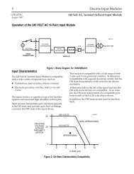
For detailed information on TMR systems, see Reference<br />
4, the IC66* Modular Redundancy Flexible Triple<br />
Modular Redundant (TMR) System User’s Manual.<br />
Supported option modules include IC697 LAN Interface<br />
modules, Programmable Coprocessor, Alphanumeric Display<br />
Coprocessor, Bus Controller for IC660/661 I/O products,<br />
Communications modules, I/O Link Interface, and all of the<br />
IC697 family of discrete and analog I/O modules.<br />
a4<strong>70</strong>59<br />
Triple PLCs<br />
Triple Genius Busses<br />
Load<br />
User Memory<br />
Triple Input Sensors<br />
Program and data memory for the CPM 7<strong>90</strong> is provided by a<br />
memory board with 1 Mbyte of battery-backed CMOS<br />
RAM. 512 Kbytes of this memory is available for the user’s<br />
application program and data. This memory board is an<br />
integral part of the CPM 7<strong>90</strong> module and is included with<br />
the module.<br />
Flash Memory<br />
This module uses flash memory for storage of the operating<br />
system firmware (this module does not support<br />
storage of user program in the flash memory). This allows<br />
updates of the firmware without disassembling the<br />
module or replacing EPROMs. The operating system<br />
firmware is updated by connecting a PC compatible<br />
computer to the module’s serial port and running the<br />
Loader software included with the firmware floppy<br />
disk.<br />
Operation, Protection, and Module Status<br />
Operation of this module can be controlled by the<br />
three-position RUN/STOP switch or remotely by an<br />
attached programmer and programming software.<br />
Program and configuration data can be locked through<br />
software passwords or manually by the memory protect<br />
keyswitch. When the key is in the protected position,<br />
Figure 1. Typical GMR System Configuration<br />
program and configuration data can only be changed by a<br />
programmer connected parallel only (to the Bus<br />
Transmitter module). The status of a <strong>CPU</strong> is indicated by<br />
the four green LEDs on the front of the module.<br />
Operating Temperature<br />
The CPM 7<strong>90</strong> requires forced air cooling for proper<br />
operation in ambient temperatures greater than 40 C<br />
(104 F). A fan capable of <strong>70</strong> CFM (including filters)<br />
should be located beneath slot 1 of the rack containing the<br />
<strong>CPU</strong>.<br />
Fan assemblies (IC697ACC721, IC697ACC724, and<br />
IC697ACC744) can be ordered for direct mounting on the<br />
IC697 rack. Refer to the applicable Programmable<br />
Controller Installation Manual for detailed information.<br />
Installation<br />
It is the responsibility of the OEM, system integrator, or end<br />
user to properly install the PLC equipment for safe and<br />
reliable operation. Product manuals provide detailed<br />
information about installation, startup, and proper use of the<br />
PLC equipment. The installation manual, shipped with your<br />
PLC programming software, describes how to properly<br />
install the equipment. If the PLC installation must comply<br />
with supported standards, such as FCC or CE Directives,<br />
please refer to the Installation Requirements for<br />
Conformance to Standards, shipped with the PLC<br />
programming software, for additional guidelines.
ÎÎ<br />
ÎÎ<br />
PLC <strong>CPU</strong>s<br />
<strong>64</strong> <strong>MHz</strong>, <strong>32</strong>-<strong>Bit</strong> <strong>Floating</strong> Point Central Processing Unit,<br />
1 Mbyte Memory, for IC66* Triple Modular Redundancy Systems<br />
3<br />
<strong>GFK</strong>-1215B<br />
November 1999<br />
<br />
<br />
<br />
<br />
Installation should not be attempted without referring to<br />
the applicable Programmable Controller Installation<br />
Manual.<br />
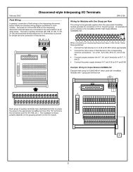
Connect the battery to either of the battery connectors on<br />
the module (see Figure 2).<br />
Put the toggle switch in the STOP position.<br />
Put the keyswitch in the Memory Protection OFF position.<br />
Make sure that rack power is off.<br />
Install the CPM 7<strong>90</strong> module in slot 1 of rack 0.<br />
Turn on power.<br />
The module should power up and the top LED should blink.<br />
When the diagnostics have completed successfully, the top<br />
LED stays on and the second and third LEDs are off. The<br />
fourth LED is off if the keyswitch is in the OFF position.<br />
The <strong>CPU</strong> is now ready to be programmed (if connected<br />
parallel, the <strong>CPU</strong> can be programmed regardless of key<br />
position). After the program has been verified the toggle<br />
switch can be moved to the appropriate operation mode<br />
position. The LEDs indicate the position of the toggle<br />
switch, memory protection status, and the state of the<br />
program.<br />
Programmer Connection, Parallel<br />
For a parallel interface (MS-DOS programmer only) the<br />
programmer is connected to the top port on the Bus<br />
Transmitter Module (IC697BEM713). Consult Reference 1<br />
for a description of programming functions.<br />
MEMORY<br />
PROTECT<br />
KEY<br />
SWITCH<br />
OPEN<br />
REPLACEMENT<br />
BATTERY<br />
CONNECTOR<br />
CURRENTLY<br />
INSTALLED<br />
BATTERY<br />
CONNECTOR<br />
1 MBYTE<br />
MEMORY BOARD<br />
ÎÎ<br />
ÎÎ ÎÎ<br />
ÎÎ<br />
ÎÎÎ<br />
ÎÎ ÎÎ<br />
ÎÎ<br />
B<br />
A<br />
T<br />
T<br />
E<br />
R<br />
Y<br />
ÎÎ ÎÎ ÎÎ<br />
ÎÎ ÎÎ<br />
ÎÎ<br />
TOP<br />
ÎÎ ÎÎ ÎÎ<br />
ÎÎ ÎÎ<br />
ÎÎ<br />
ÎÎ ÎÎ ÎÎ<br />
ÎÎ Î<br />
Î<br />
ÎÎ<br />
ÎÎ Î<br />
Î<br />
ÎÎ<br />
ÎÎ Î<br />
Î<br />
ÎÎ<br />
ÎÎ Î<br />
Î<br />
ÎÎ<br />
ÎÎ<br />
Î<br />
Î<br />
ÎÎ<br />
ÎÎ Î<br />
ÎÎ<br />
Î<br />
CPM 7<strong>90</strong><br />
a4<strong>70</strong>81<br />
OFF<br />
ÎÎ<br />
ON<br />
REMOTE PROGRAMMER<br />
Î<br />
MEMORY PROTECT<br />
KEY POSITION<br />
FRONT<br />
MODULE OK<br />
Î<br />
RUN<br />
OUTPUTS Î ENABLED<br />
MEMORY<br />
PROTECT<br />
REMOTE<br />
Î<br />
ÎPROGRAMMER<br />
ONLY<br />
ON = OK, ENABLED,<br />
PROTECTED<br />
RUN WITH<br />
OUTPUTS<br />
ENABLED<br />
RUN WITH<br />
OUTPUTS<br />
DISABLED<br />
STOP<br />
BATTERY<br />
CONNECTORS<br />
INSTALL NEW<br />
BATTERY BEFORE<br />
UNPLUGGING OLD<br />
BATTERY. USE<br />
IC697ACC<strong>70</strong>1<br />
MODULE FUNCTION<br />
ÎÎ<br />
Î<br />
ÎÎ<br />
Î<br />
<strong>64</strong> <strong>MHz</strong> <strong>32</strong> BIT CENTRAL<br />
PROCESSING UNIT WITH<br />
FLOATING POINT MATH<br />
COPROCESSOR, IN-SYSTEM<br />
UPGRADEABLE FIRMWARE<br />
ÎÎ<br />
Î<br />
SERIAL PORT<br />
RS-485<br />
COMPATIBLE<br />
ÎÎ<br />
Î<br />
Î<br />
ÎÎ<br />
ÎÎ Î<br />
ÎÎ<br />
Î<br />
USE THIS MODULE<br />
IN SLOT 1 ONLY<br />
MODULE<br />
IC697CPM7<strong>90</strong><br />
LABEL<br />
44A726758–149R01<br />
ÎÎ<br />
Î<br />
CPM 7<strong>90</strong><br />
ÎÎ<br />
Î<br />
Figure 2. CPM 7<strong>90</strong> - Location of Major Features
4<br />
<strong>GFK</strong>-1215B<br />
November 1999<br />
PLC <strong>CPU</strong>s<br />
<strong>64</strong> <strong>MHz</strong>, <strong>32</strong>-<strong>Bit</strong> <strong>Floating</strong> Point Central Processing Unit,<br />
1 Mbyte Memory, for IC66* Triple Modular Redundancy Systems<br />
a47100<br />
PLC A<br />
PLC B<br />
PLC C<br />
C<br />
P<br />
U<br />
C<br />
P<br />
U<br />
C<br />
P<br />
U<br />
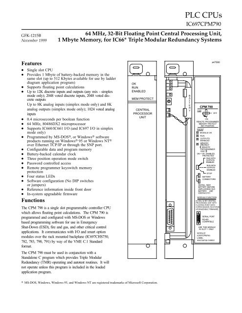
Multidrop Cable<br />
RS–2<strong>32</strong>/422<br />
Converter<br />
Multidrop cable is catalog number<br />
IC6<strong>90</strong>CBL714 (1 cable). Two cables<br />
are needed for 3 <strong>CPU</strong>s.<br />
Figure 3. System Configuration, Serial Connection to Programmer<br />
Serial Port<br />
The 15-pin D-connector provides the connection to an<br />
RS-485 compatible serial port on the <strong>CPU</strong> (see Figure 3).<br />
This port provides a serial connection to a Work Station<br />
Interface board installed in the programming computer.<br />
The serial connection can also be made from the serial port<br />
on the <strong>CPU</strong> to the serial port on the programming computer,<br />
or other serial device, through the RS-422/RS-485 to<br />
RS-2<strong>32</strong> Converter (IC6<strong>90</strong>ACC<strong>90</strong>0) or RS-2<strong>32</strong> to RS-422<br />
Miniconverter (IC6<strong>90</strong>ACC<strong>90</strong>1). This connection can be<br />
made with available cables or you may build cables to fit the<br />
needs of your particular application. See reference 3 for<br />
more information on serial communications.<br />
For more detailed information on configuration of TMR<br />
systems and communications between PLCs in the system,<br />
refer to the Modular Redundancy Flexible Triple Modular<br />
Redundant (TMR) System User’s Manual.<br />
Programmer Connection, Ethernet<br />
TCP/IP<br />
Connecting your programmer via an Ethernet TCP/IP<br />
network requires installation of an Ethernet Interface<br />
module in the PLC. This can be either the Ethernet<br />
Controller, IC697CMM741, or Ethernet Interface (Type<br />
2), IC697CMM742. Before connecting your<br />
programmer and PLC to the Ethernet TCP/IP network<br />
you must set the IP address in the Ethernet Interface.<br />
After setting the IP address, connect the PLC and the<br />
programmer running Windows software to the<br />
Ethernet Interface.<br />
For more detailed information on Ethernet TCP/IP,<br />
refer to the TCP/IP Ethernet Communications (Type 2)<br />
User’s Manual, and the Windows programming<br />
manual, <strong>GFK</strong>-1295.
PLC <strong>CPU</strong>s<br />
<strong>64</strong> <strong>MHz</strong>, <strong>32</strong>-<strong>Bit</strong> <strong>Floating</strong> Point Central Processing Unit,<br />
1 Mbyte Memory, for IC66* Triple Modular Redundancy Systems<br />
5<br />
<strong>GFK</strong>-1215B<br />
November 1999<br />
Configuration<br />
The IC697 <strong>CPU</strong> and I/O system is configured with<br />
MS-DOS or Windows based programming software.<br />
There are no DIP switches or jumpers used to configure<br />
the system. The <strong>CPU</strong> verifies the actual module and rack<br />
configuration at power-up and periodically during<br />
operation. The actual configuration must be the same as<br />
the programmed configuration. Deviations are reported to<br />
the <strong>CPU</strong> alarm processor function for configured fault<br />
response. Consult Reference 1 for a description of<br />
configuration functions.<br />
Battery<br />
A lithium battery (IC697ACC<strong>70</strong>1) is installed as shown in<br />
Figure 2. This battery maintains program and data<br />
memory when power is removed and operates the calendar<br />
clock. Be sure to install the new battery before removing<br />
the old battery. If during power-up diagnostics a low<br />
battery is detected, the MODULE OK LED (top LED) will<br />
not stay on. Specific indication of a low battery state is<br />
detailed in Reference 2.<br />
Removing a Module<br />
The instructions below should be followed when removing<br />
a module from its slot in a rack.<br />
<br />
<br />
<br />
Grasp the board firmly at the top and bottom of the<br />
board cover with your thumbs on the front of the<br />
cover and your fingers on the plastic clips on the back<br />
of the cover.<br />
Squeeze the rack clips on the back of the cover with<br />
your fingers to disengage the clip from the rack rail<br />
and pull the board firmly to remove it from the<br />
backplane connector.<br />
Slide the board along the card guide and remove it<br />
from the rack.<br />
Table 1. References<br />
Reference<br />
Title<br />
1 Programming Software User’s Manual<br />
2 Programmable Controller Reference Manual<br />
3 Programmable Controller Installation Manual<br />
4 IC660/IC661 Modular Redundancy Flexible Triple Modular<br />
Redundant (TMR) System User’s Manual
6<br />
<strong>GFK</strong>-1215B<br />
November 1999<br />
PLC <strong>CPU</strong>s<br />
<strong>64</strong> <strong>MHz</strong>, <strong>32</strong>-<strong>Bit</strong> <strong>Floating</strong> Point Central Processing Unit,<br />
1 Mbyte Memory, for IC66* Triple Modular Redundancy Systems<br />
Battery<br />
Table 2. Specifications for IC697CPM7<strong>90</strong><br />
Shelf life 10 years at 20 C (68 F)<br />
Memory retention<br />
Current required from 5V bus<br />
Operating Temperature<br />
Time of Day Clock accuracy<br />
Elapsed Time Clock (internal timing) accuracy<br />
Serial Port<br />
RS422/485 compatible<br />
6 months nominal without applied power.<br />
3.3 Amps nominal<br />
0 to 60 C (<strong>32</strong> F to 140 F); <strong>70</strong> CFM forced air required<br />
0 to 40 C (<strong>32</strong> F to 104 F); without forced air<br />
" 3.5 seconds per day maximum<br />
" .01% maximum<br />
Programmer Serial Attachment<br />
VME System designed to support the VME standard C.1<br />
Refer to <strong>GFK</strong>-0867B, or later for product standards and general specifications.<br />
Table 3. Ordering Information<br />
Description<br />
Central Processing Unit<br />
<strong>64</strong> <strong>MHz</strong>, <strong>32</strong>-<strong>Bit</strong>, <strong>Floating</strong> Point, 1 Mbyte Memory<br />
For IC66* Triple Modular Redundancy Systems<br />
Catalog Number<br />
IC697CPM7<strong>90</strong><br />
Lithium Battery<br />
Rack Fan Assembly, 120 VAC<br />
Rack Fan Assembly, 240 VAC<br />
Rack Fan Assembly, 24 VDC<br />
IC697ACC<strong>70</strong>1<br />
IC697ACC721<br />
IC697ACC724<br />
IC697ACC744<br />
Note: For Conformal Coat option, or Low Temperature Testing option please consult<br />
the factory for price and availability.