C1 and C3 - Assembly Instructions - Life Fitness
C1 and C3 - Assembly Instructions - Life Fitness
C1 and C3 - Assembly Instructions - Life Fitness

You also want an ePaper? Increase the reach of your titles
YUMPU automatically turns print PDFs into web optimized ePapers that Google loves.
© 2006 <strong>Life</strong> <strong>Fitness</strong>, a division of Brunswick Corporation. All rights reserved. <strong>Life</strong> <strong>Fitness</strong> is a registered trademarks of Brunswick<br />
Corporation. Any use of this trademark, without the express written consent of <strong>Life</strong> <strong>Fitness</strong> is forbidden. 8114201 Rev A-1 (07/06)<br />
5100 N. RIVER ROAD, SCHILLER PARK, ILLINOIS 60176<br />
LIFEFITNESS.COM<br />
<strong>Life</strong> <strong>Fitness</strong> offers a full line of premier fitness equipment for the home.<br />
TOTAL-BODY ELLIPTICAL CROSS-TRAINERS | TREADMILLS | LIFECYCLE EXERCISE BIKES<br />
STAIRCLIMBERS | GYM SYSTEMS<br />
®<br />
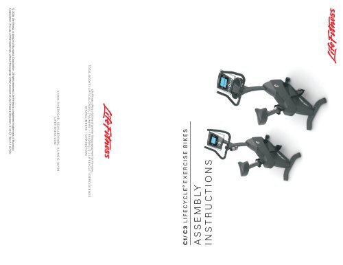
<strong>C1</strong>/ C 3 LIFECYCLE EXERCISE BIKES<br />
R<br />
ASSEMBLY<br />
INSTRUCTIONS
Tools Required: Metric Wrench Set, Metric Allen Wrench Set, Phillips Screwdriver<br />
1. Locate <strong>and</strong> install the two LEVELER FEET (A) to the bottom of the REAR STABILIZER (B).<br />
With the bends facing rearward, attach the REAR STABILIZER (B) to the BASE UNIT (C) using two 50 mm BUTTON HEAD SCREWS (1) from the top of the REAR<br />
STABILIZER BRACKET (D) <strong>and</strong> two 20 mm BUTTON HEAD SCREWS (2) from the front side of the REAR STABILIZER BRACKET. Tighten the SCREWS securely.<br />
2. Locate the MONOCOLUMN (E). Slide the MONOCOLUMN COVER (F) onto the MONOCOLUMN as shown. Slide the MONOCOLUMN COVER up to the CONSOLE<br />
SUPPORT (G).<br />
NOTE: A plastic zip-tie has been included to keep the MONOCOLUMN COVER (F) from falling during assembly.<br />
NOTE: The MONOCOLUMN COVER (F) must slide over the WIRE TIE (H) taped to the front of the MONOCOLUMN (E).<br />
With the CONSOLE SUPPORT (G) facing the front of the unit as shown, slide the MONOCOLUMN (E) into the MONOCOLUMN BRACKET (J) of the BASE UNIT (C) .<br />
Slide the MONOCOLUMN down until it is fully seated. Secure the MONOCOLUMN to the MONOCOLUMN BRACKET using two 100 mm HEX HEAD BOLTS (3) <strong>and</strong><br />
three THICK FLAT WASHERS (4) (as shown) from the rear side of the MONOCOLUMN. Use two 60 mm HEX HEAD BOLTS (5) <strong>and</strong> two THICK FLAT WASHERS (4)<br />
from the user left side of the MONOCOLUMN BRACKET. Tighten the BOLTS securely.<br />
CAUTION: Be careful not to pinch the WIRE (K) leading from the MONOCOLUMN BRACKET (J) when inserting the MONOCOLUMN (E) into the MONOCOLUMN<br />
BRACKET.<br />
3. Untape the WIRE TIE (H) attached to the front of the MONOCOLUMN (E). Carefully pull the CONSOLE WIRE (L) through the SIDE ACCESS HOLE (M) of the<br />
MONOCOLUMN (E). Feed the CONSOLE WIRE through the GROMMET (N) as shown <strong>and</strong> insert the GROMMET into the SIDE ACCESS HOLE.<br />
Connect the WIRE (K) leading from the MONOCOLUMN BRACKET (J) to the corresponding CONSOLE WIRE (L) from the SIDE ACCESS HOLE (M) of the<br />
MONOCOLUMN (E). Slide the MONOCOLUMN COVER (F) downward to the meet the MAIN SHROUDS. Secure the MONOCOLUMN COVER to the MAIN<br />
SHROUDS using four 12 mm PHILLIPS SCREWS (6) <strong>and</strong> matching FLAT WASHERS (7). Tighten the SCREWS securely. Do not overtighten the SCREWS.<br />
4. Locate the SEAT (O) <strong>and</strong> SEAT POST (P). Remove the three NYLOCK NUTS (8) <strong>and</strong> FLAT WASHERS (9) from the threaded studs on the bottom of the SEAT. Align<br />
the threaded studs of the SEAT with the mounting holes in the SEAT POST MOUNTING PLATE (Q). Secure the seat to the SEAT POST MOUNTING PLATE using the<br />
three previously removed NYLOCK NUTS <strong>and</strong> FLAT WASHERS. Tighten the NUTS securely.<br />
Locate the SEAT POST CAP (R). With the curved side facing upward toward the SEAT (O) <strong>and</strong> the inside notch aligned with the SEAT POST (P) adjustment decal,<br />
slide the SEAT POST CAP over the SEAT POST.<br />
Locate <strong>and</strong> slide the SEAT POST SPACER (S) over the end of the SEAT POST (P). Be sure the locking tabs fully engage the holes located at the bottom of the SEAT<br />
POST. Secure the SEAT POST SPACER using two 8 mm PHILLIPS SCREWS (10).<br />
With the nose of the SEAT (O) facing forward, insert the SEAT POST (P) into the SEAT POST SUPPORT (T).<br />
Slide the SEAT POST CAP (R) downward to meet the top of the SEAT POST SUPPORT (T). Secure the SEAT POST CAP to the SEAT POST SUPPORT using two 6<br />
mm PHILLIPS SCREWS (11). Tighten the SCREWS securely. Do not overtighten the SCREWS.<br />
Begin inserting the SEAT ADJUSTMENT KNOB (U). Lift upward on the SEAT (O) <strong>and</strong> SEAT POST (P) until the SEAT POST locks into a position. Tighten the SEAT<br />
ADJUSTMENT KNOB fully. Insert the 6 mm PHILLIPS SCREW W/LOCKING COMPOUND (12) <strong>and</strong> tighten securely.<br />
5.<br />
Item Qty Description<br />
<strong>C1</strong> <strong>C3</strong> 1) 2)<br />
1<br />
2<br />
3<br />
4<br />
5<br />
6<br />
7<br />
8<br />
9<br />
10<br />
11<br />
12<br />
13<br />
14<br />
15<br />
16<br />
17<br />
2<br />
2<br />
2<br />
5<br />
2<br />
4<br />
4<br />
3<br />
3<br />
2<br />
2<br />
1<br />
4<br />
4<br />
2<br />
4<br />
2<br />
2<br />
2<br />
5<br />
2<br />
4<br />
4<br />
3<br />
3<br />
2<br />
2<br />
1<br />
2<br />
4<br />
4<br />
0<br />
4<br />
<strong>Assembly</strong> Guide:<br />
Look for the number coded<br />
hardware bags that match the<br />
assembly sequence.<br />
Physical Dimensions:<br />
<strong>C1</strong><br />
Length:<br />
Width:<br />
Height:<br />
Weight:<br />
<strong>C3</strong><br />
Length:<br />
Width:<br />
Height:<br />
Weight:<br />
41 inches / 104 centimeters<br />
23.5 inches / 60 centimeters<br />
56 inches / 142 centimeters<br />
116 pounds / 52.6 kilograms<br />
45 inches / 114 centimeters<br />
27.2 inches / 69 centimeters<br />
56 inches / 142 centimeters<br />
112.8 pounds / 51 kilograms<br />
50 mm Button Head Screw<br />
20 mm Button Head Screw<br />
100 mm Hex Head Bolt<br />
Thick Flat Washer - 16 mm O.D.<br />
60 mm Hex Head Bolt<br />
12 mm Small Head Phillips Screw<br />
Flat Washer - 12 mm O.D.<br />
Nylock Nut (on seat)<br />
Flat Washer (on seat)<br />
8mmPhillips<br />
Screw<br />
6mmPhillips<br />
Screw<br />
6mmPhillips<br />
Screw<br />
w/Locking Compound<br />
8mmPhillips<br />
Screw<br />
15 mm Button Head Screw<br />
Flat Washer - 18 mm O.D.<br />
12 mm Large Head Phillips Screw<br />
12 mm Self-Tapping Screw<br />
3)<br />
5) 6)<br />
8) 9)<br />
13)<br />
11) 12)<br />
14) 15)<br />
16)<br />
Hardware List<br />
<strong>C3</strong> Only: Locate the ACCESSORY TRAY (V). Position the ACCESSORY TRAY near the top of the MONOCOLUMN (E) at the DISPLAY CONSOLE BRACKET (W).<br />
While holding the CONSOLE WIRE (X) <strong>and</strong> HEART RATE WIRE (Y), cut the wire tie securing the CONSOLE WIRES to the DISPLAY CONSOLE BRACKET. Feed the<br />
CONSOLE WIRES through the center hole of the ACCESSORY TRAY MOUNTING BRACKET (Z). Secure the ACCESSORY TRAY to the DISPLAY CONSOLE BRACKET<br />
using two 8 mm PHILLIPS SCREWS (13). Tighten the SCREWS securely.<br />
CAUTION: Be careful not to pinch the CONSOLE WIRE (X) <strong>and</strong> HEART RATE WIRE (Y) when securing the ACCESSORY TRAY (V) to the DISPLAY CONSOLE<br />
BRACKET (W).<br />
NOTE: Be careful not to let the CONSOLE WIRE (X) <strong>and</strong> HEART RATE WIRE (Y) fall into the DISPLAY CONSOLE BRACKET (W).<br />
Remove the DISPLAY CONSOLE (AA) from its shipping carton. Position the DISPLAY CONSOLE above the ACCESSORY TRAY (V). Connect the CONSOLE WIRE (X),<br />
HEART RATE WIRE (Y) (RED), <strong>and</strong> GROUND WIRE (BB) (GREEN) to the corresponding JACKS located on the back of the DISPLAY CONSOLE. Secure the DISPLAY<br />
CONSOLE to the DISPLAY CONSOLE BRACKET (W) using four 12 mm SELF TAPPING SCREWS (17). Tighten the SCREWS securely. Do not overtighten the<br />
SCREWS.<br />
4)<br />
7)<br />
6) 7)<br />
17)<br />
10)<br />
10 20 30 40 50 60 70 80 90 100 110 120 130 140 150 160<br />
<strong>Assembly</strong> Sequence<br />
6.<br />
1<br />
D<br />
B<br />
C<br />
2<br />
A<br />
AA<br />
13<br />
V<br />
Q<br />
9<br />
8<br />
R<br />
11<br />
CC<br />
12<br />
DD<br />
14<br />
15<br />
O<br />
Z<br />
P<br />
10<br />
T<br />
<strong>C1</strong> & <strong>C3</strong> Upright Bikes<br />
<strong>C1</strong> Only: Remove the DISPLAY CONSOLE (AA) from its shipping carton. While holding the CONSOLE WIRE (X) <strong>and</strong> HEART RATE WIRE (Y) (RED), cut the wire tie<br />
securing the CONSOLE WIRE to the DISPLAY CONSOLE BRACKET (W). Position the DISPLAY CONSOLE above the DISPLAY CONSOLE BRACKET. Connect the<br />
CONSOLE WIRE, HEART RATE WIRE <strong>and</strong> GROUND WIRE (BB) (GREEN) to the corresponding JACKS located on the back of the DISPLAY CONSOLE. Secure the<br />
DISPLAY CONSOLE to the DISPLAY CONSOLE BRACKET using four 12 mm SELF TAPPING SCREWS (17). Tighten the SCREWS securely. Do not overtighten the<br />
SCREWS.<br />
NOTE: Be careful not to let the CONSOLE WIRE (X) <strong>and</strong> HEART RATE WIRE (Y) fall into the DISPLAY CONSOLE BRACKET (W).<br />
Locate the HANDLEBAR ASSEMBLY (CC). With the h<strong>and</strong>lebars facing forward, position the HANDLEBAR ASSEMBLY near the top of the MONOCOLUMN (E).<br />
Connect the WIRES (DD) leading from the HANDLEBAR ASSEMBLY <strong>and</strong> the MONOCOLUMN. Slide the HANDLEBAR ASSEMBLY fully into the MONOCOLUMN.<br />
Secure the HANDLEBAR ASSEMBLY to the MONOCOLUMN using four 15 mm BUTTON HEAD SCREWS (14) <strong>and</strong> matching FLAT WASHERS (15). Tighten the<br />
SCREWS securely.<br />
CAUTION: Be careful not the pinch the WIRES (DD) when sliding the HANDLEBAR ASSEMBLY (CC) into the MONOCOLUMN (E).<br />
Insert the ENDCAP (KK) into the CONSOLE BRACKET TUBE (LL).<br />
7. Locate the RIGHT PEDAL (EE) (marked with an "R") <strong>and</strong> PEDAL STRAP (FF) (marked with an "R"). With the side of the PEDAL STRAP marked with an “R” facing<br />
upward, slide the slotted end of the PEDAL STRAP through the left slot in the PEDAL. Fasten one of the slots onto the tab located under the left slot of the<br />
PEDAL. Bend the PEDAL STRAP upward <strong>and</strong> slide the remaining end of the PEDAL STRAP through the right slot in the PEDAL <strong>and</strong> into the strap adjustment clip.<br />
The PEDAL STRAP should securely engage the strap adjustment clip.<br />
Install the RIGHT PEDAL (EE) to the USER RIGHT CRANK ARM (GG). Repeat for the LEFT PEDAL (marked with an "L") <strong>and</strong> PEDAL STRAP (marked with an "L").<br />
NOTE: The LEFT PEDAL has reverse threads.<br />
NOTE: Pedals need to be securely tightened or clicking may occur.<br />
8. <strong>C1</strong> Only: Locate the WATER BOTTLE BRACKET (HH). Secure the WATER BOTTLE BRACKET to the underside of the MONOCOLUMN (E) using two 12 mm<br />
LARGE HEAD PHILLIPS SCREWS (16). Tighten the screws securely. Insert the WATER BOTTLE (JJ) into the WATER BOTTLE BRACKET.<br />
Position the unit in the desired location for use. The unit can be easily moved into place by lifting the rear of the unit <strong>and</strong> rolling it on the front rollers. Level the unit<br />
before use. Refer to the leveling instructions stated in the Operation Manual.<br />
5<br />
1. 4.<br />
7.<br />
Rear Stabilizer<br />
Seat & Seat Post Pedals<br />
2.&3.<br />
Monocolumn, Wiring & Cover<br />
6 7<br />
M<br />
G<br />
N<br />
H<br />
L E<br />
J<br />
4<br />
4 K<br />
3<br />
F<br />
S<br />
5.&6.<br />
Accessory Tray, Console &<br />
H<strong>and</strong>lebar<br />
X<br />
U<br />
Y<br />
LL<br />
BB<br />
W<br />
GG<br />
E<br />
FF<br />
EE<br />
8. (<strong>C1</strong> Only)<br />
Water Bottle & Bracket<br />
KK<br />
17<br />
BB<br />
Y<br />
X<br />
JJ<br />
HH<br />
16