New Crash Discrimination Algorithms and Locations of ...
New Crash Discrimination Algorithms and Locations of ...
New Crash Discrimination Algorithms and Locations of ...

You also want an ePaper? Increase the reach of your titles
YUMPU automatically turns print PDFs into web optimized ePapers that Google loves.
Seoul 2000 FISITA World Automotive Congress<br />
June 12-15, 2000, Seoul, Korea<br />
F2000G421<br />
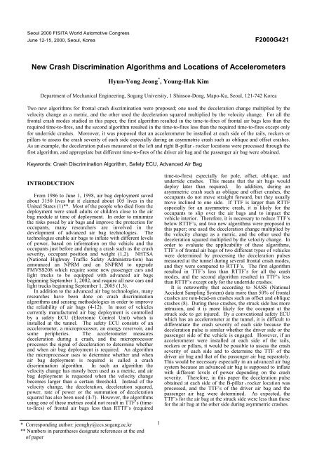
<strong>New</strong> <strong>Crash</strong> <strong>Discrimination</strong> <strong>Algorithms</strong> <strong>and</strong> <strong>Locations</strong> <strong>of</strong> Accelerometers<br />
Hyun-Yong Jeong * , Young-Hak Kim<br />
Department <strong>of</strong> Mechanical Engineering, Sogang University, 1 Shinsoo-Dong, Mapo-Ku, Seoul, 121-742 Korea<br />
Two new algorithms for frontal crash discrimination were proposed; one used the deceleration change multiplied by the<br />
velocity change as a metric, <strong>and</strong> the other used the deceleration squared multiplied by the velocity change. For all the<br />
frontal crash modes studied in this paper, the first algorithm resulted in the time-to-fires <strong>of</strong> frontal air bags less than the<br />
required time-to-fires, <strong>and</strong> the second algorithm resulted in the time-to-fires less than the required time-to-fires except only<br />
for underride crashes. Moreover, it was proposed that an accelerometer be installed at each side <strong>of</strong> the rails, rockers or<br />
pillars to assess the crash severity <strong>of</strong> each side especially during an asymmetric crash such as oblique <strong>and</strong> <strong>of</strong>fset crashes.<br />
As an example, the deceleration pulses measured at the left <strong>and</strong> right B-pillar • rocker locations were processed through the<br />
first algorithm, <strong>and</strong> appropriate but different time-to-fires <strong>of</strong> the driver air bag <strong>and</strong> the passenger air bag were obtained.<br />
Keywords: <strong>Crash</strong> <strong>Discrimination</strong> Algorithm, Safety ECU, Advanced Air Bag<br />
INTRODUCTION<br />
From 1986 to June 1, 1998, air bag deployment saved<br />
about 3150 lives but it claimed about 105 lives in the<br />
United States (1)**. Most <strong>of</strong> the people who died from the<br />
deployment were small adults or children close to the air<br />
bag module at time <strong>of</strong> deployment. In order to minimize<br />
the risks posed by air bags <strong>and</strong> improve the protection for<br />
occupants, many researchers are involved in the<br />
development <strong>of</strong> advanced air bag technologies. The<br />
technologies enable air bags to inflate with different levels<br />
<strong>of</strong> power, based on information on the vehicle <strong>and</strong> the<br />
occupants just before <strong>and</strong> during a crash such as the crash<br />
severity, occupant position <strong>and</strong> weight (1,2). NHTSA<br />
(National Highway Traffic Safety Administra-tion) has<br />
announced an NPRM <strong>and</strong> an SNPRM to upgrade<br />
FMVSS208 which require some new passenger cars <strong>and</strong><br />
light trucks to be equipped with advanced air bags<br />
beginning September 1, 2002, <strong>and</strong> require all new cars <strong>and</strong><br />
light trucks beginning September 1, 2005 (1,3).<br />
In addition to the advanced air bag technologies, many<br />
researches have been done on crash discrimination<br />
algorithms <strong>and</strong> sensing methodologies in order to improve<br />
the reliability <strong>of</strong> air bags (4-12). In most <strong>of</strong> vehicles<br />
currently manufactured air bag deployment is controlled<br />
by a safety ECU (Electronic Control Unit) which is<br />
installed at the tunnel. The safety ECU consists <strong>of</strong> an<br />
accelerometer, a microprocessor, an energy reservoir, <strong>and</strong><br />
some peripheries. The accelerometer measures<br />
deceleration during a crash, <strong>and</strong> the microprocessor<br />
processes the signal <strong>of</strong> deceleration to determine whether<br />
<strong>and</strong> when air bag deployment is required. An algorithm<br />
the microprocessor uses to determine whether <strong>and</strong> when<br />
air bag deployment is required is called a crash<br />
discrimination algorithm. In such an algorithm the<br />
velocity change has mostly been used as a metric, <strong>and</strong> air<br />
bag deployment is requested when the velocity change<br />
becomes larger than a certain threshold. Instead <strong>of</strong> the<br />
velocity change, the deceleration, deceleration squared,<br />
power, rate <strong>of</strong> power or the summation <strong>of</strong> deceleration<br />
squared has also been used (4-7). However, the algorithms<br />
using one <strong>of</strong> these metrics could not result in TTF’s (timeto-fires)<br />
<strong>of</strong> frontal air bags less than RTTF’s (required<br />
time-to-fires) especially for pole, <strong>of</strong>fset, oblique, <strong>and</strong><br />
underride crashes. This means that the air bags would<br />
deploy later than required. In addition, during an<br />
asymmetric crash such as oblique <strong>and</strong> <strong>of</strong>fset crashes, the<br />
occupants do not move straight forward, but they usually<br />
move inclined to one side. If TTF is larger than RTTF<br />
especially for an asymmetric crash, it is likely for the<br />
occupants to slip over the air bags <strong>and</strong> to impact the<br />
vehicle interior. Therefore, it is necessary to reduce TTF’s<br />
below RTTF’s, <strong>and</strong> two new algorithms were proposed in<br />
this paper; one used the deceleration change multiplied by<br />
the velocity change as a metric, <strong>and</strong> the other used the<br />
deceleration squared multiplied by the velocity change. In<br />
order to evaluate the applicability <strong>of</strong> these algorithms,<br />
TTF’s <strong>of</strong> frontal air bags <strong>of</strong> two different types <strong>of</strong> vehicles<br />
were determined by processing the deceleration pulses<br />
measured at the tunnel during several frontal crash modes,<br />
<strong>and</strong> they were compared to RTTF’s. The first algorithm<br />
resulted in TTF’s less than RTTF’s for all the crash<br />
modes, <strong>and</strong> the second algorithm resulted in TTF’s less<br />
than RTTF’s except only for the underride crashes.<br />
It is noteworthy that according to NASS (National<br />
Accident Sampling System) data more than 50% <strong>of</strong> frontal<br />
crashes are non-head-on crashes such as <strong>of</strong>fset <strong>and</strong> oblique<br />
crashes (8). During these crashes, the struck side has more<br />
intrusion, <strong>and</strong> it is more likely for the occupant at the<br />
struck side to get injured. By a conventional safety ECU<br />
which has an accelerometer at the tunnel, it is difficult to<br />
differentiate the crash severity <strong>of</strong> each side because the<br />
deceleration pulse is similar whether the driver side or the<br />
passenger side <strong>of</strong> the vehicle is engaged. However, if an<br />
accelerometer were installed at each side <strong>of</strong> the rails,<br />
rockers or pillars, it would be possible to assess the crash<br />
severity <strong>of</strong> each side <strong>and</strong> to determine the TTF <strong>of</strong> the<br />
driver air bag <strong>and</strong> that <strong>of</strong> the passenger air bag separately.<br />
This would be necessary especially in an advanced air bag<br />
system because an advanced air bag is supposed to inflate<br />
with different levels <strong>of</strong> power depending on the crash<br />
severity. Therefore, in this paper the deceleration pulse<br />
obtained at each side <strong>of</strong> the B-pillar • rocker location was<br />
processed, <strong>and</strong> the TTF’s <strong>of</strong> the driver air bag <strong>and</strong> the<br />
passenger air bag were determined. As expected, the<br />
TTF’s for the air bag at the struck side were less than those<br />
for the air bag at the other side during asymmetric crashes.<br />
* Corresponding author: jeonghy@ccs.sogang.ac.kr<br />
** Numbers in parentheses designate references at the end<br />
<strong>of</strong> paper<br />
1
SIGNAL PROCESSING<br />
A conventional safety ECU consists <strong>of</strong> an<br />
accelerometer, a microprocessor, an energy reservoir, a<br />
safing sensor, <strong>and</strong> some peripheries. The accelerometer<br />
measures <strong>and</strong> sends the deceleration signal to the<br />
microprocessor through a built-in anti-aliasing low pass<br />
filter (13). The sampling <strong>and</strong> the cut-<strong>of</strong>f frequencies for<br />
the anti-aliasing filter were determined, based on the<br />
frequency <strong>and</strong> amplitude information about 35 mph barrier<br />
crash pulses obtained through the FFT (Fast Fourier<br />
Transformation). The microprocessor samples the<br />
deceleration signal <strong>and</strong> filters it through a s<strong>of</strong>tware to<br />
remove undesirable noises, which prevents air bags from<br />
deploying at a low speed crash. As an example, an<br />
unfiltered signal <strong>and</strong> the corresponding filtered signal are<br />
shown in Fig. 1.<br />
deceleration<br />
Figure 1 – Deceleration signals before <strong>and</strong><br />
after the digital filtering<br />
NEW CRASH DISCRIMINATION<br />
ALGORITHMS<br />
unfiltered dec.<br />
filtered dec.<br />
0 0.05 0.1 0.15 0.2 0.25<br />
time (sec)<br />
In this paper two algorithms were proposed for crash<br />
discrimination. The first one used the deceleration change<br />
multiplied by the velocity change as a metric, <strong>and</strong> the<br />
second one used the deceleration squared multiplied by the<br />
velocity change. The deceleration is related to the impact<br />
force occurring during a crash, <strong>and</strong> the deceleration<br />
change is related to the impact force change. In addition,<br />
the velocity change is related to the summation <strong>of</strong> the<br />
impact force from the beginning <strong>of</strong> a crash because the<br />
velocity change is equal to the integral <strong>of</strong> the deceleration.<br />
Therefore, both the impact force change (or the impact<br />
force) <strong>and</strong> the accumulation <strong>of</strong> the impact force can be<br />
monitored simultaneously through the metrics. Moreover,<br />
the noises in the deceleration signal can be effectively<br />
eliminated, being multiplied by the velocity change<br />
because the velocity change signal is very smooth.<br />
It is well known that a “hard” pulse occurs during a<br />
crash with the full front engaged with a hard structure, <strong>and</strong><br />
the impact force or the impact force change is high. In<br />
contrast, a “s<strong>of</strong>t” pulse occurs during a crash with only a<br />
portion <strong>of</strong> the front engaged such as pole, <strong>of</strong>fset, oblique,<br />
<strong>and</strong> underride crashes, <strong>and</strong> the accumulation <strong>of</strong> the impact<br />
force is high. Therefore, through the algorithms proposed<br />
in this paper a crash can be detected adequately whether it<br />
entails a “hard” pulse or a “s<strong>of</strong>t” pulse.<br />
RTTF’s <strong>of</strong> frontal air bags can be determined by so call<br />
the 5 in – 30 msec rule (14). That is, RTTF is equal to the<br />
time for the occupant to move forward by 5 in minus the<br />
time for the air bag to inflate more than 80%, which is<br />
about 30 msec. The time for the 5 in movement can be<br />
determined by two methods. The first method is to<br />
integrate twice the deceleration signal measured at any<br />
point in the uncrushed zone such as at the tunnel or at the<br />
B-pillar • rocker location. The second method is to<br />
measure the time by the analysis <strong>of</strong> the crash film.<br />
The TTF’s <strong>and</strong> RTTF’s for the frontal air bags <strong>of</strong> a<br />
medium size passenger car currently manufactured in<br />
Korea were obtained, <strong>and</strong> the ratios <strong>of</strong> TTF’s to RTTF’s<br />
are shown in Table 1 <strong>and</strong> 2. Here TTF’s were determined<br />
by the algorithms proposed in this paper <strong>and</strong> other<br />
algorithms published in the literature which use the<br />
deceleration, deceleration squared, power, power rate, or<br />
the summation <strong>of</strong> deceleration squared as a metric (4-7).<br />
A metric can be processed as a function <strong>of</strong> the time from<br />
the beginning <strong>of</strong> a crash, but it can also be processed as a<br />
function <strong>of</strong> the velocity change. The ratios shown in Table<br />
1 were obtained when the metrics were processed as a<br />
function <strong>of</strong> the time, <strong>and</strong> the ratios shown in Table 2 were<br />
obtained when the metrics were processed as a function <strong>of</strong><br />
the velocity change. In Table 1 <strong>and</strong> 2, NF (no fire) means<br />
that the air bag deployment is not needed.<br />
The results shown in Table 1 indicate that the first<br />
algorithm proposed in this paper resulted in TTF’s less<br />
than RTTF’s except only for the 20 mph underride crash,<br />
but the other algorithms including the second algorithm<br />
proposed in this paper resulted in TTF’s larger than<br />
RTTF’s for the 19 mph pole, 20 mph underride, <strong>and</strong> 30<br />
mph pole crashes. The results shown in Table 2 indicate<br />
that the first algorithm resulted in TTF’s less than RTTF’s<br />
for all the crash modes, <strong>and</strong> the second algorithm resulted<br />
in TTF’s less than RTTF’s except only for the 20 mph<br />
underride crash. However, the other algorithms resulted in<br />
TTF’s larger than RTTF’s for the frontal, pole, oblique,<br />
<strong>of</strong>fset <strong>and</strong> underride crashes.<br />
Table 1 – TTF/RTTF obtained when the metric is<br />
represented as a function <strong>of</strong> the time<br />
Units : %<br />
<strong>Crash</strong> mode<br />
|∆dec.| dec. 2<br />
dec. dec. 2 power power Σdec. 2<br />
x vel x vel<br />
rate<br />
8mph frontal NF NF NF NF NF NF NF<br />
15km/h ffset NF NF NF NF NF NF NF<br />
14mph frontal 58 58 55 62 62 60 68<br />
30mph frontal 60 47 45 50 50 50 55<br />
35mph frontal 83 83 63 89 94 73 89<br />
19mph pole 98 127 125 132 128 128 173<br />
20mph<br />
underride<br />
120 123 111 131 130 124 162<br />
22mph<br />
left oblique<br />
40 33 30 34 38 33 37<br />
22mph<br />
right oblique<br />
43 36 31 37 44 36 39<br />
30mph pole 95 110 108 163 158 160 183<br />
30mph<br />
right oblique<br />
41 39 38 43 43 41 50<br />
35mph <strong>of</strong>fset 27 22 39 25 32 24 27<br />
2
Table 2 – TTF/RTTF obtained when the metric is<br />
represented as a function <strong>of</strong> the velocity change<br />
Units : %<br />
<strong>Crash</strong> mode<br />
|∆dec.| dec. 2<br />
dec. dec. 2 power power Σdec. 2<br />
x vel x vel<br />
rate<br />
8mph frontal NF NF NF NF NF NF NF<br />
15km/h ffset NF NF NF NF NF NF NF<br />
14mph frontal 58 60 58 67 72 62 95<br />
30mph frontal 47 47 45 53 53 50 76<br />
35mph frontal 83 89 57 99 104 94 140<br />
19mph pole 88 89 142 155 89 90 165<br />
20mph<br />
underride<br />
90 108 110 116 110 111 164<br />
22mph<br />
left oblique<br />
40 37 30 195 185 193 44<br />
22mph<br />
right oblique<br />
42 43 31 183 170 46 59<br />
30mph pole 37 97 107 108 97 98 127<br />
30mph<br />
right oblique<br />
39 39 39 46 70 43 57<br />
35mph <strong>of</strong>fset 27 24 19 178 154 34 47<br />
not discern which side is engaged during an asymmetric<br />
crash. This would be a serious problem especially for an<br />
advanced air bag system because an advanced air bag<br />
system is supposed to modulate the air bag power based on<br />
the crash severity.<br />
The TTF’s <strong>and</strong> RTTF’s for the frontal air bags <strong>of</strong> a<br />
sports utility vehicle currently manufactured in Korea were<br />
also obtained with the metrics processed as a function <strong>of</strong><br />
the velocity change, <strong>and</strong> the ratios <strong>of</strong> TTF’s to RTTF’s are<br />
shown in Table 3. Once again, the first algorithm resulted<br />
in TTF’s less than RTTF’s for all the crash modes, <strong>and</strong> the<br />
second algorithm resulted in TTF’s less than RTTF’s<br />
except only for the 20 mph underride crash although the<br />
other algorithms resulted in TTF’s larger than RTTF’s for<br />
pole, oblique, <strong>of</strong>fset, <strong>and</strong> underride crashes.<br />
Table 3 – TTF/RTTF obtained when the metric is<br />
represented as a function <strong>of</strong> the velocity change<br />
Units : %<br />
<strong>Crash</strong> mode<br />
|∆dec.| dec. 2<br />
dec. dec. 2 power power Σdec. 2<br />
x vel x vel<br />
rate<br />
8mph frontal NF NF NF NF NF NF NF<br />
15km/h ffset NF NF NF NF NF NF NF<br />
14mph frontal 58 60 58 67 72 62 100<br />
30mph frontal 60 60 57 67 67 63 100<br />
35mph frontal 83 89 57 99 104 94 146<br />
19mph pole 89 89 142 155 89 90 165<br />
20mph<br />
underride<br />
90 121 116 127 121 122 180<br />
22mph<br />
left oblique<br />
40 37 30 195 185 193 67<br />
22mph<br />
right oblique<br />
43 43 31 183 170 46 67<br />
30mph pole 37 97 107 108 97 98 132<br />
30mph<br />
right oblique<br />
39 39 39 46 70 43 138<br />
35mph <strong>of</strong>fset 27 24 20 183 159 35 103<br />
NEW LOCATIONS OF ACCELEROMETERS<br />
In most <strong>of</strong> vehicles a safety ECU is located at the<br />
tunnel, i.e. at the middle <strong>of</strong> the vehicle from each side, <strong>and</strong><br />
it has an accelerometer. Therefore, a similar deceleration<br />
pulse is measured by the accelerometer whether the driver<br />
side or the passenger side is engaged during an asymmetric<br />
crash. However, there occurs more intrusion at the struck<br />
side, <strong>and</strong> it is more likely for the occupant at the struck<br />
side to get injured. Deceleration pulses measured by the<br />
accelerometer during a left oblique crash <strong>and</strong> a right<br />
oblique crash are shown in Fig. 2, <strong>and</strong> they are slightly<br />
different due to asymmetric arrangement <strong>of</strong> components<br />
under the hood. This implies that the safety ECU would<br />
Figure 2 – Deceleration pulses measured at the tunnel<br />
during the left <strong>and</strong> right oblique crashes<br />
However, if an accelerometer were installed at each<br />
side <strong>of</strong> the rails, rockers or pillars, the accelerometer<br />
installed at the side closer to the struck point would sense a<br />
severer deceleration pulse during an asymmetric crash.<br />
Figure 3(a) shows the deceleration pulses measured at the<br />
left <strong>and</strong> right B-pillar • rocker locations during a left<br />
oblique crash <strong>of</strong> the medium size passenger car. It is clear<br />
that the pulse measured at the left location is severer at the<br />
early stage <strong>of</strong> the event. Figure 3(b) shows the<br />
deceleration pulses measured during a right oblique crash,<br />
<strong>and</strong> the pulse measured at the right location is severer.<br />
Since the deceleration change multiplied by the velocity<br />
change turned out to be the best metric, the metric was<br />
plotted as a function <strong>of</strong> the velocity change for the left<br />
oblique crash <strong>and</strong> the right oblique crash in Fig. 4(a) <strong>and</strong><br />
(b), respectively. Once again, the pulse measured at the<br />
side closer to the struck point is severer at the early stage<br />
<strong>of</strong> the event. In Table 4, the ratios <strong>of</strong> TTF to RTTF were<br />
shown for oblique <strong>and</strong> <strong>of</strong>fset crashes. Here RTTF’s were<br />
obtained by integrating twice the deceleration pulses<br />
measured at the tunnel because they were almost the same<br />
as RTTF’s obtained from the deceleration pulse measured<br />
at either the left B-pillar • rocker location or the right B-<br />
pillar • rocker location. It is noteworthy that TTF’s were<br />
less than RTTF’s for all the asymmetric crashes studied<br />
here, <strong>and</strong> TTF’s for the struck side were quite less than<br />
those for the other side. This implies that the air bag at the<br />
struck side would deploy earlier <strong>and</strong>/or more powerfully<br />
than the air bag at the other side. In Table 5, the ratios<br />
were also shown for symmetric crashes. All the ratios<br />
were less than 1, <strong>and</strong> TTF’s for both sides were almost the<br />
same.<br />
CONCLUSION<br />
In this paper, two crash discrimination algorithms were<br />
3
Figure 3(a) – Deceleration signals obtained at the B-<br />
pillar-rocker locations for the left oblique<br />
at the left b-pillar<br />
at the right b-pillar<br />
|∆ deceleration| x velocity change<br />
0 0.2 0.4 0.6 0.8 1 1.2 1.4 1.6 1.8 2<br />
velocity change (mph)<br />
Figure 3(a) – Deceleration pulses obtained at the B-pillarrocker<br />
locations during the left oblique crash<br />
Figure 4(b) - |∆decel.| x velocity change signals for the left<br />
oblique crash<br />
Table 4 – TTF/RTTF obtained from the deceleration<br />
pulses measured at the B-pillar-rocker locations<br />
<strong>Crash</strong> mode Sensor location TTF / RTTF<br />
15km/h <strong>of</strong>fset left b-pillar NF<br />
right b-pillar NF<br />
22mph left left b-pillar 32%<br />
oblique right b-pillar 80%<br />
22mph right left b-pillar 51%<br />
oblique right b-pillar 37%<br />
35mph <strong>of</strong>fset left b-pillar 28%<br />
right b-pillar 40%<br />
Figure 3(b) – Deceleration pulses obtained at the B-pillarrocker<br />
locations during the right oblique crash<br />
at the left b-pillar<br />
Figure 4(a) - |∆decel.| x velocity change signals for the left<br />
at the right b-pillar<br />
oblique crash<br />
|∆ deceleration| x velocity change<br />
Figure 4(b) - |∆decel.| x velocity change signals for the left<br />
oblique crash<br />
0 0.2 0.4 0.6 0.8 1 1.2 1.4 1.6 1.8 2<br />
velocity change (mph)<br />
Table 4 – TTF/RTTF obtained from the deceleration<br />
Figure 4(a) - |∆decel.| x velocity change signals for the left<br />
oblique crash<br />
Table 5 – TTF/RTTF obtained from the deceleration<br />
pulses measured at the B-pillar-rocker locations during<br />
symmetric crashes<br />
<strong>Crash</strong> mode Seosor location TTF / RTTF<br />
14mph frontal left b-pillar 57%<br />
right b-pillar 57%<br />
30mph frontal left b-pillar 60%<br />
right b-pillar 63%<br />
35mph frontal left b-pillar 83%<br />
right b-pillar 83%<br />
20mph left b-pillar 82%<br />
underride right b-pillar 95%<br />
30mph pole left b-pillar 95%<br />
right b-pillar 83%<br />
proposed, <strong>and</strong> they were evaluated for several frontal crash<br />
modes <strong>of</strong> two different types <strong>of</strong> vehicles. The algorithm in<br />
which the metric <strong>of</strong> the deceleration change multiplied by<br />
velocity change was processed as a function <strong>of</strong> the velocity<br />
change resulted in TTF’s less than RTTF’s for all the<br />
frontal crash modes considered in this paper. The<br />
algorithm in which the metric <strong>of</strong> the deceleration squared<br />
multiplied by the velocity change was processed as a<br />
function <strong>of</strong> the velocity change also resulted in TTF’s less<br />
than RTTF’s except only for the underride crashes.<br />
Through the metrics both the impact force change (or the<br />
4
impact force) <strong>and</strong> the accumulation <strong>of</strong> the impact force can<br />
be monitored simultaneously. That is, both a “hard” pulse<br />
occurring during a full-barrier-type crash <strong>and</strong> a “s<strong>of</strong>t”<br />
pulse occurring during a pole, underride, oblique or <strong>of</strong>fset<br />
crash can be detected early enough.<br />
Moreover, the deceleration pulses measured at left <strong>and</strong><br />
right B-pillar • rocker locations were processed to<br />
determine TTF’s for the driver air bag <strong>and</strong> passenger air<br />
bag separately, utilizing the metric <strong>of</strong> the deceleration<br />
change multiplied by the velocity change. The TTF’s for<br />
the driver air bag were smaller than those for the passenger<br />
air bags under left oblique crashes <strong>and</strong> <strong>of</strong>fset crashes with<br />
the driver side engaged, but vise versa under right oblique<br />
crashes. However, TTF’s for both air bags were almost<br />
the same during symmetric crashes. This implies that it<br />
would be possible to assess the crash severity <strong>of</strong> each side<br />
adequately during an asymmetric crash or a symmetric<br />
crash if an accelerometer were installed at each side <strong>of</strong> the<br />
rails, rockers or pillars. It is common to install the sensing<br />
device for the side impact crashes at the B-pillar • rocker<br />
locations. Therefore, it would be possible to pack together<br />
the sensing devices both for the frontal crashes <strong>and</strong> the<br />
side impact crashes.<br />
[14] Breed, D. S., <strong>and</strong> Castelli, V. 1988. Problems in<br />
Design <strong>and</strong> Engineering <strong>of</strong> Airbag Systems. SAE<br />
Technical Paper 880724.<br />
REFERENCES<br />
[1] NHTSA Docket No. NHTSA 99-4405; Notice 1.<br />
[2] JPL Final Report. 1998. Advanced Air Bag<br />
Technology Assessment.<br />
[3] NHTSA Docket No. NHTSA 99-6407; Notice 1.<br />
[4] Allen, J. L. 1992. Power-Rate <strong>Crash</strong> Sensing Method<br />
for Safety Device Actuation. SAE Technical Paper<br />
920478.<br />
[5] Gioutsos, T. 1992. A Predictive Based Algorithm for<br />
Actuation <strong>of</strong> an Airbag. SAE Technical Paper 920479.<br />
[6] Kanamoto, J, Miyamori, M., Jinno, K., <strong>and</strong> Hirao, M.<br />
1994. Electronic <strong>Crash</strong> Sensing Unit for Airbag. SAE<br />
Technical Paper 940624.<br />
[7] Park, S. W., <strong>and</strong> Jeon, M. C. 1998. <strong>Crash</strong><br />
<strong>Discrimination</strong> Algorithm for Airbag Electronic<br />
Single-point Sensor. KSAE 98134 (in Korean).<br />
[8] Adams, T. G., Huang, M., Hultman, R. W., Marsh, J.<br />
C., <strong>and</strong> Henson, S. E. 1990. The Development <strong>of</strong> an<br />
Advanced Air Bag <strong>Crash</strong> Sensing System. SAE<br />
Technical Paper 905140.<br />
[9] Breed, D. S. S<strong>and</strong>ers, W. T., <strong>and</strong> Castelli, V. 1992. A<br />
Critique <strong>of</strong> Single Point Sensing. SAE Technical<br />
Paper 920124.<br />
[10] Mahon, G. L., <strong>and</strong> Hensler, R. L. 1993. Trade<strong>of</strong>fs<br />
Encountered in Evaluating <strong>Crash</strong> Sensing Systems.<br />
SAE Technical Paper 930648.<br />
[11] Kelly, J. P. 1993. Sensing Considerations <strong>and</strong><br />
Trade<strong>of</strong>fs for Single Point Sensing. SAE Technical<br />
Paper 932916.<br />
[12] Rich, D. B., Kosiak, W. K., Manlove, G. J., <strong>and</strong><br />
Schwarz, D. L. 1997. A Remotely Mounted <strong>Crash</strong><br />
Detection System. SAE Technical Paper 973240.<br />
[13] Oppenheim, A. V., <strong>and</strong> Schafer, R. W. 1989.<br />
Discrete-Time Signal Processing. 2 nd ed. Prentice-<br />
Hall: 142-147.<br />
5