New Crash Discrimination Algorithms and Locations of ...
New Crash Discrimination Algorithms and Locations of ...
New Crash Discrimination Algorithms and Locations of ...

You also want an ePaper? Increase the reach of your titles
YUMPU automatically turns print PDFs into web optimized ePapers that Google loves.
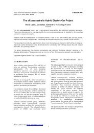
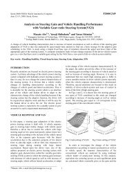
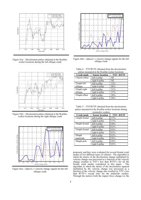
Figure 3(a) – Deceleration signals obtained at the B-<br />
pillar-rocker locations for the left oblique<br />
at the left b-pillar<br />
at the right b-pillar<br />
|∆ deceleration| x velocity change<br />
0 0.2 0.4 0.6 0.8 1 1.2 1.4 1.6 1.8 2<br />
velocity change (mph)<br />
Figure 3(a) – Deceleration pulses obtained at the B-pillarrocker<br />
locations during the left oblique crash<br />
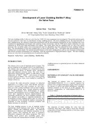
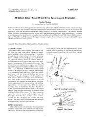
Figure 4(b) - |∆decel.| x velocity change signals for the left<br />
oblique crash<br />
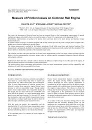
Table 4 – TTF/RTTF obtained from the deceleration<br />
pulses measured at the B-pillar-rocker locations<br />
<strong>Crash</strong> mode Sensor location TTF / RTTF<br />
15km/h <strong>of</strong>fset left b-pillar NF<br />
right b-pillar NF<br />
22mph left left b-pillar 32%<br />
oblique right b-pillar 80%<br />
22mph right left b-pillar 51%<br />
oblique right b-pillar 37%<br />
35mph <strong>of</strong>fset left b-pillar 28%<br />
right b-pillar 40%<br />
Figure 3(b) – Deceleration pulses obtained at the B-pillarrocker<br />
locations during the right oblique crash<br />
at the left b-pillar<br />
Figure 4(a) - |∆decel.| x velocity change signals for the left<br />
at the right b-pillar<br />
oblique crash<br />
|∆ deceleration| x velocity change<br />
Figure 4(b) - |∆decel.| x velocity change signals for the left<br />
oblique crash<br />
0 0.2 0.4 0.6 0.8 1 1.2 1.4 1.6 1.8 2<br />
velocity change (mph)<br />
Table 4 – TTF/RTTF obtained from the deceleration<br />
Figure 4(a) - |∆decel.| x velocity change signals for the left<br />
oblique crash<br />
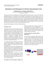
Table 5 – TTF/RTTF obtained from the deceleration<br />
pulses measured at the B-pillar-rocker locations during<br />
symmetric crashes<br />
<strong>Crash</strong> mode Seosor location TTF / RTTF<br />
14mph frontal left b-pillar 57%<br />
right b-pillar 57%<br />
30mph frontal left b-pillar 60%<br />
right b-pillar 63%<br />
35mph frontal left b-pillar 83%<br />
right b-pillar 83%<br />
20mph left b-pillar 82%<br />
underride right b-pillar 95%<br />
30mph pole left b-pillar 95%<br />
right b-pillar 83%<br />
proposed, <strong>and</strong> they were evaluated for several frontal crash<br />
modes <strong>of</strong> two different types <strong>of</strong> vehicles. The algorithm in<br />
which the metric <strong>of</strong> the deceleration change multiplied by<br />
velocity change was processed as a function <strong>of</strong> the velocity<br />
change resulted in TTF’s less than RTTF’s for all the<br />
frontal crash modes considered in this paper. The<br />
algorithm in which the metric <strong>of</strong> the deceleration squared<br />
multiplied by the velocity change was processed as a<br />
function <strong>of</strong> the velocity change also resulted in TTF’s less<br />
than RTTF’s except only for the underride crashes.<br />
Through the metrics both the impact force change (or the<br />
4