New Crash Discrimination Algorithms and Locations of ...
New Crash Discrimination Algorithms and Locations of ...
New Crash Discrimination Algorithms and Locations of ...

Create successful ePaper yourself
Turn your PDF publications into a flip-book with our unique Google optimized e-Paper software.
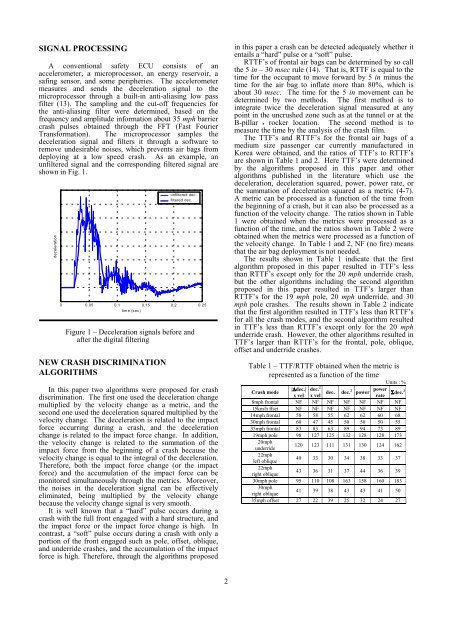
SIGNAL PROCESSING<br />
A conventional safety ECU consists <strong>of</strong> an<br />
accelerometer, a microprocessor, an energy reservoir, a<br />
safing sensor, <strong>and</strong> some peripheries. The accelerometer<br />
measures <strong>and</strong> sends the deceleration signal to the<br />
microprocessor through a built-in anti-aliasing low pass<br />
filter (13). The sampling <strong>and</strong> the cut-<strong>of</strong>f frequencies for<br />
the anti-aliasing filter were determined, based on the<br />
frequency <strong>and</strong> amplitude information about 35 mph barrier<br />
crash pulses obtained through the FFT (Fast Fourier<br />
Transformation). The microprocessor samples the<br />
deceleration signal <strong>and</strong> filters it through a s<strong>of</strong>tware to<br />
remove undesirable noises, which prevents air bags from<br />
deploying at a low speed crash. As an example, an<br />
unfiltered signal <strong>and</strong> the corresponding filtered signal are<br />
shown in Fig. 1.<br />
deceleration<br />
Figure 1 – Deceleration signals before <strong>and</strong><br />
after the digital filtering<br />
NEW CRASH DISCRIMINATION<br />
ALGORITHMS<br />
unfiltered dec.<br />
filtered dec.<br />
0 0.05 0.1 0.15 0.2 0.25<br />
time (sec)<br />
In this paper two algorithms were proposed for crash<br />
discrimination. The first one used the deceleration change<br />
multiplied by the velocity change as a metric, <strong>and</strong> the<br />
second one used the deceleration squared multiplied by the<br />
velocity change. The deceleration is related to the impact<br />
force occurring during a crash, <strong>and</strong> the deceleration<br />
change is related to the impact force change. In addition,<br />
the velocity change is related to the summation <strong>of</strong> the<br />
impact force from the beginning <strong>of</strong> a crash because the<br />
velocity change is equal to the integral <strong>of</strong> the deceleration.<br />
Therefore, both the impact force change (or the impact<br />
force) <strong>and</strong> the accumulation <strong>of</strong> the impact force can be<br />
monitored simultaneously through the metrics. Moreover,<br />
the noises in the deceleration signal can be effectively<br />
eliminated, being multiplied by the velocity change<br />
because the velocity change signal is very smooth.<br />
It is well known that a “hard” pulse occurs during a<br />
crash with the full front engaged with a hard structure, <strong>and</strong><br />
the impact force or the impact force change is high. In<br />
contrast, a “s<strong>of</strong>t” pulse occurs during a crash with only a<br />
portion <strong>of</strong> the front engaged such as pole, <strong>of</strong>fset, oblique,<br />
<strong>and</strong> underride crashes, <strong>and</strong> the accumulation <strong>of</strong> the impact<br />
force is high. Therefore, through the algorithms proposed<br />
in this paper a crash can be detected adequately whether it<br />
entails a “hard” pulse or a “s<strong>of</strong>t” pulse.<br />
RTTF’s <strong>of</strong> frontal air bags can be determined by so call<br />
the 5 in – 30 msec rule (14). That is, RTTF is equal to the<br />
time for the occupant to move forward by 5 in minus the<br />
time for the air bag to inflate more than 80%, which is<br />
about 30 msec. The time for the 5 in movement can be<br />
determined by two methods. The first method is to<br />
integrate twice the deceleration signal measured at any<br />
point in the uncrushed zone such as at the tunnel or at the<br />
B-pillar • rocker location. The second method is to<br />
measure the time by the analysis <strong>of</strong> the crash film.<br />
The TTF’s <strong>and</strong> RTTF’s for the frontal air bags <strong>of</strong> a<br />
medium size passenger car currently manufactured in<br />
Korea were obtained, <strong>and</strong> the ratios <strong>of</strong> TTF’s to RTTF’s<br />
are shown in Table 1 <strong>and</strong> 2. Here TTF’s were determined<br />
by the algorithms proposed in this paper <strong>and</strong> other<br />
algorithms published in the literature which use the<br />
deceleration, deceleration squared, power, power rate, or<br />
the summation <strong>of</strong> deceleration squared as a metric (4-7).<br />
A metric can be processed as a function <strong>of</strong> the time from<br />
the beginning <strong>of</strong> a crash, but it can also be processed as a<br />
function <strong>of</strong> the velocity change. The ratios shown in Table<br />
1 were obtained when the metrics were processed as a<br />
function <strong>of</strong> the time, <strong>and</strong> the ratios shown in Table 2 were<br />
obtained when the metrics were processed as a function <strong>of</strong><br />
the velocity change. In Table 1 <strong>and</strong> 2, NF (no fire) means<br />
that the air bag deployment is not needed.<br />
The results shown in Table 1 indicate that the first<br />
algorithm proposed in this paper resulted in TTF’s less<br />
than RTTF’s except only for the 20 mph underride crash,<br />
but the other algorithms including the second algorithm<br />
proposed in this paper resulted in TTF’s larger than<br />
RTTF’s for the 19 mph pole, 20 mph underride, <strong>and</strong> 30<br />
mph pole crashes. The results shown in Table 2 indicate<br />
that the first algorithm resulted in TTF’s less than RTTF’s<br />
for all the crash modes, <strong>and</strong> the second algorithm resulted<br />
in TTF’s less than RTTF’s except only for the 20 mph<br />
underride crash. However, the other algorithms resulted in<br />
TTF’s larger than RTTF’s for the frontal, pole, oblique,<br />
<strong>of</strong>fset <strong>and</strong> underride crashes.<br />
Table 1 – TTF/RTTF obtained when the metric is<br />
represented as a function <strong>of</strong> the time<br />
Units : %<br />
<strong>Crash</strong> mode<br />
|∆dec.| dec. 2<br />
dec. dec. 2 power power Σdec. 2<br />
x vel x vel<br />
rate<br />
8mph frontal NF NF NF NF NF NF NF<br />
15km/h ffset NF NF NF NF NF NF NF<br />
14mph frontal 58 58 55 62 62 60 68<br />
30mph frontal 60 47 45 50 50 50 55<br />
35mph frontal 83 83 63 89 94 73 89<br />
19mph pole 98 127 125 132 128 128 173<br />
20mph<br />
underride<br />
120 123 111 131 130 124 162<br />
22mph<br />
left oblique<br />
40 33 30 34 38 33 37<br />
22mph<br />
right oblique<br />
43 36 31 37 44 36 39<br />
30mph pole 95 110 108 163 158 160 183<br />
30mph<br />
right oblique<br />
41 39 38 43 43 41 50<br />
35mph <strong>of</strong>fset 27 22 39 25 32 24 27<br />
2